new web: http://bdml.stanford.edu/pmwiki
TWiki > Manufacturing Web>ManufacturingHome>SDMFabTechniques (10 Aug 2010, DanAukes)
|
Contents:
Sub Pages (Full WebMap) |
SDM Fabrication Techniques
Other Pages
- SDMsensorFab describes MotohideHatanaka 's work on developing hair-like sensors.
- Spine/Claw related work by MicheleLanzetta, not only SDM: SpineScale? , SpineMaterials, SpineFabrication (a PPT presentation with photos). Some photos and more explanations in SpineAxialCompliance, SpinedLegs, SpineTriplets, SqueezingOptions and SqueezingPrototypes
- FootFab describes some of the manufacturing processes used to develop feet for the RiSE robot.
- GripperFab describes MiguelPiedrahita 's work on building a gripping mechanism with integrated sensing.
- SDMgeckoFingers is about work to create highly compliant finger-like structures to which gecko setae could be mounted.
- CompliantMembranesInSDM is about work to create highly compliant fluid filled membrane integrated into an SDM part - on which Ron Fearing's synthestic gecko setae could be mounted. A prototype is described in SpineFabrication.
Fiber-reinforced flexures(to be added)
Sliding Prismatic Joints
Work is underway to see if prismatic joints consisting of urethane sliding on urethane would be smooth enough for micro-spine compliance. See SeparatedCompliance? for more details.Silicone Inserts
An important aspect of the SDM process is the use of sacrifical material to fill spaces we wish to keep free of urethane. Yellow wax is often used for this purpose by melting the wax, pouring it into the in-process mold, and machining selectively for a subsequent pour. In some circumstances, silicone inserts are a good alternative to pouring yellow wax. Silicone RTV can be obtained from TAP Plastics. Silicone thinner fluid (also from TAP) is recommended, as it decreases the viscosity and makes for an easier casting process. A good example of the use of silicone inserts is described in the section on Universal JointsAdvantages vs. yellow wax:
- Geometry: Silicone can be molded into a desired shape prior to use as a sacrifical material. Thus, it can provide features such as undercuts which are impossible with the yellow wax process.
- Cleaning: Silicone inserts do not bond to the curing urethane at all. Once the part is cured and extracted, the silicone inserts can be easily peeled away. This is much easier than the removal of yellow wax, which is often quite tedious.
- Reuse: Since the silicone inserts peel off easily, they generally remain intact and can be reused.
Disadvantages vs. yellow wax:
- Machinability: Silicone is extremely soft and cannot be effectively machined. For some designs, this rules out the use of silicone.
- Time & effort: Machining a mold and casting the urethane take more time compared to the process using yellow wax, where melted wax is simply poured into the cavity and fly-cut to leave a smooth surface.
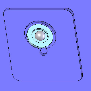
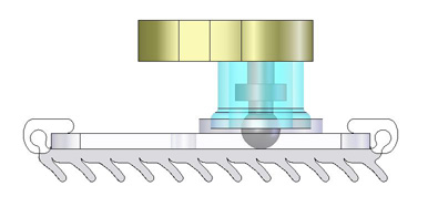
Universal (Ball) Joint
A simple implementation of a universal ball joint was used in a Sticky Foot design for RiSE. The joint consisted of a ball stud directly embedded in urethane. Ball stud is made for RC cars, available from http://www.yokomousa.com, part # ZC-206, or ZC-206L for longer studs.Initial proof-of-concept:
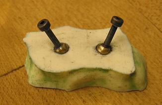
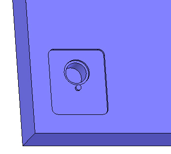
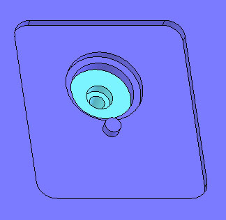
Manufacturing process:
The range of motion of the joint is determined by the depth at which the ball stud is embedded. For this reason, it is important to control the depth precisely. Depth was controlled through use of silicone rings which were fabricated ahead of time. The rings were designed to fit snugly around the ball stud and expose only the desired portion of the ball stud. See pictures below.The silicone rings had the added advantage of protecting the threads on the ball stud, thus keeping them clean for use as the interface to the ankle.
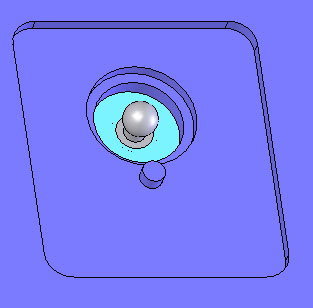
 Ball was coated generously with mold release spray prior to casting urethane around it.
Upon curing, ball stud is stuck in place but is easily cracked free.
Lubrication of joint using graphite powder resulted in very smooth joint movement. Wet lubricants were not as effective.
Ball was coated generously with mold release spray prior to casting urethane around it.
Upon curing, ball stud is stuck in place but is easily cracked free.
Lubrication of joint using graphite powder resulted in very smooth joint movement. Wet lubricants were not as effective.
Sealed Hollow Chambers
This method was developed by MiguelPiedrahita for the purpose of creating a pressure-sensing approach to measuring foot forces.The basic approach is shown in the picture below:
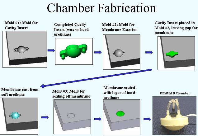 Note that the first few steps results in a concave structure. This approach has subsequently been used to create concave structures in more recent designs, such as the running feet shown in RunningMovie.
 Ideas, requests, problems regarding TWiki? Send feedback