new web: http://bdml.stanford.edu/pmwiki
TWiki > Rise Web>ClimbingRobot > LegDesign>StanfordTestTrack (27 Sep 2005, AMcClung? )
Foot tests from July 2004 can be found at StanfordFootDesignTests along with a new foot design fabricated at the end of July. -- WillP? - 03 Aug 2004
-- MarkCutkosky - 17 Jun 2004
-- MarkCutkosky - 13 Feb 2004 'thought I'd post this to get any feedback, suggestions.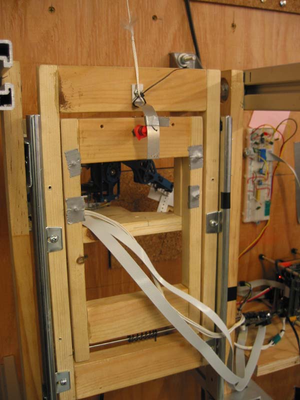
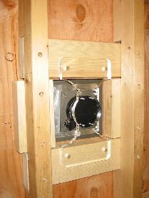 * Back side view of force platform
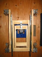
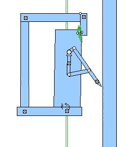
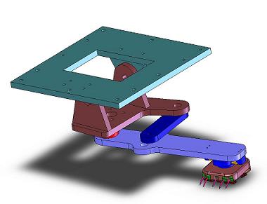 Plan view of compliant frame (looking into wall). _____Solid Works model of 4-Bar linkage leg
Stanford Test Track
- Purpose: Test various lower leg and foot designs, gather data on expected forces
- Concept: a vertical or inclined track that guides a body with a single leg. Think of it as a saggital plane projection of 1/6 of the RiSE platform. The body is attached to the track via a compliant pivot, to roughly approximate the effect of having multiple legs in contact with the wall.
- StanfordTestTrackSummer04Tests - Testing notes for the summer
- EmilyMa created some testing documentation: EmilysTestInstructions
- Creating a page for RisePlatformSetup
- RisePlatformStatus gives the status of the full RiSE robot platform (SURISE) at the Stanford Test Track
- RisePlatformTestInstructions gives details on operating the platform
- RiSEPlatformUpdatingCodeNotes gives information on how to update the code
-
 RiSEHelloWorldTutorial is a tutorial for the generation of a new mode for the RiSE platform (code development)
- RisePlatformGaitBuilder contains some useful notes on changing gaits
- Creating a page for RiseLegSetup (MarkCutkosky 6-29-04)
- RiseLegTestSoftware describes the software and steps necessary for testing
- RiseLegStatus gives the status of the RiSE leg at the Stanford Test Track
- RiseLegClimbingParameters lists and describes the 14 trajectory parameters
- RiseLegTestInstructions give detailed instructions to perform testing on the track
- RiseLegTestSurfaces contains some pictures of brief descriptions of the surfaces mounted to the force plate
- Initial test track results prepared for April 16, 2004 Teleconference: Trajectory_initial_experiment.ppt
- FootAndLegTrajectoryTestingProcedure describes the test procedure for the acrylic leg and RHex stack
-- MarkCutkosky - 13 Feb 2004 'thought I'd post this to get any feedback, suggestions.
New RiSE Leg
- We have attached a current RiSE leg to our test track.
- The new leg was mounted in a similar fashion to the older arcylic prototype leg, which is documented below.
Older notes
-
- So this is sort of a saggital plane complement to the interesting modeling that DanGoldman has been doing.
- Actually, because the leg/hip unit has 2 DOF, we can rotate the 4-bar linkage plane into almost any orientation
-
 view Working Model animation (avi):
- Questions to address:
- What is the best combination of lower leg compliance in the saggital plane?
- What claw and foot designs work best on various surfaces?
- What forces do the feet produce as a function of differenc loading strategies?
- What ankle compliance works best?
- What foot trajectory is most effective?
- what other questions should we try to answer?
Details
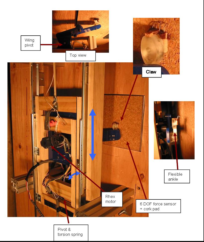
- The wall surface is a 4x8 sheet of plywood. Various materials can be attached to the surface (e.g. cork, rubber, concrete slab...)
- The center of the wall has a force plate approximately 15cm x 15 cm attached to a 6-axis ATI force torque sensor.
- The "track" currently consists of two ball-bearing drawer slides attached to a wooden frame. The Frame has a spring-loaded hinge that allows the leg/hip unit to bear against the wall.
- The first version of the leg/hip unit consists two RHex motors and controllers attached to a laser-cut acrylic linkage. The linkage is a 4-bar rocker crank (like the RiSE platform) and a second "wing" degree of freedom. Unlike RiSE, the two axes are in a serial chain (no differential). Arbitrary motion profiles can be loaded into the two motors using the RHex lib software. The strength of the lasercut acrylic precludes high forces. We may need to switch to a better material.
- The effective weight of the frame and leg can be adjusted by using counterweights attached to a string and pulley.
- The compliance between the leg/hip unit and the frame can be adjusted
* Back side view of force platform
Plan view of compliant frame (looking into wall). _____Solid Works model of 4-Bar linkage leg
Ideas, requests, problems regarding TWiki? Send feedback