new web: http://bdml.stanford.edu/pmwiki
TWiki > Rise Web>ClimbingRobot>LegDesign (25 Feb 2004, MarkCutkosky)
Main.MarkCutkosky - 01 Aug 2003; modified Jan 2004 to add an index & roughly sort in reverse chron. order.
Topics:
Updates, Mechanism Explorations, Design Tools (synthesis, analysis)
In conjunction with WillP. I am planning on working on foot/ankle/leg design. (See FootSensingAndActuation). What changes do we need to make to a sprawl design in order to enable climbing and vertical running? What is a minimally complex leg design that will work for running up a wall? What motion or actuation is necessary in order to apply/retract the feet when climbing? Can an elegant mechanism for selecting the adhesion method (hook, glue, dry adhesion) be incorporated into the leg design? Preliminary slides on leg design ideas. Includes some tools and models in Working Model. Some detail on four-bar and pantograph geometries, and discussion of short term goals. Download and unzip this zip file: -- MarkCutkosky - 05 Aug 2003
Here are a couple of useful references regarding pantograph legs, workspace, etc. for small robots
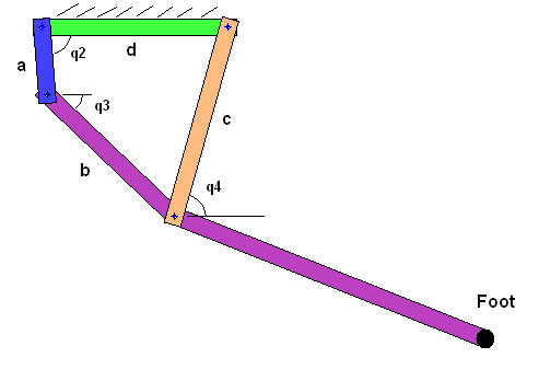
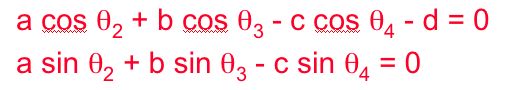
This figure shows a simplified schematic of the actual 4-bar linkage designed by AaroSaunders. The link angles q2,q3,and q4 are defined relative to the ground link (green), and are defined to be positive as drawn. Note that on the actual robot, the ground link is not horizontal. For a specified input angle q2, we can solve for angles q3 and q4. As mentioned in the posting by MarkCutkosky, one way to do this is to write a vector loop for the linkage and solve the two resulting equations. For the diagram shown here, the resulting equations are:
a*cos(q2)+b*cos(q3)+c*cos(q4)-d = 0
a*sin(q2)+b*sin(q3)-c*sin(q4) = 0
These equations can be solved symbolically with Matlab or Mathematica. Alternatively, in complex form this equation can be written as:
a*exp(i*q2)+b*exp(i*q3)+c*exp(i*q4)-d = 0
The complex form of the equation can be solved for q3 and q4 by hand by using a few tricks involving complex conjugates, and then solving for two independent quadratics in e^(i*q3) and e^(i*q4).
The solutions generated by Mathematica are shown below (replacing q's with thetas). Note: to simplify the expression, link length a has been set to 1.:
Once angles q3 and q4 have been found, calculating their angular velocities w3 and w4 is straightforward. Given an angular velocity w2,
w3 = - w2*(a*sin(q2+q4))/(b*sin(q3+q4))
w4 = - w2*(a*sin(q2-q3))/(c*sin(q3+q4))
The velocity of the foot can then be calculated (where "e" is the length of the lower leg, and theta is the angle between "b" and "e"):
velocity of foot in frame "d" = -w2*a*Ay> + w3*e*sin(theta)*Bx> + (-w3*b-w3*e*cos(theta))*By>
Right now I have the foot velocity expressed in terms of unit vectors Ay>, Bx>, and By>. Ay> is perpendicular to linkA, Bx> is along link B, and By> is perpendicular to link B. The velocity can be expressed in terms of unit vectors fixed in link D, which is more intuitive, but I haven't quite gotten there.
That's all for now, will be updated soon. -- MarkCutkosky 24 Jan 2004: DanKoditschek was asking about "parametric leg models." I assume he means the kinematic analysis problem and not the synthesis problem, which is covered in AaroSaunders notes below. There are many texts on 4-bar linkage position, velocity and force analysis. The following link has a nice set of powerpoint slides for the standard vector loop equations.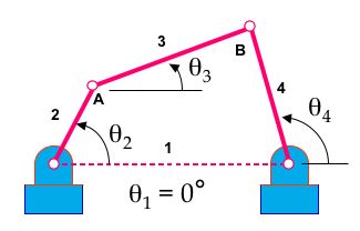
 where a, b, c and d are the lengths of links 2, 3, 4 and 1, respectively. Theta2 is the known input, so solve for theta3 and theta4 using real and imaginary parts of the loop equation, as listed above. Once we have the angles we can embed a coordinate frame in the third link, which is part of the leg.
-- AaroSaunders? - 12 Sep 2003
The main input for the 4bar leg design is going to be the foot trajectory. For simple paths it may be possible to iterate linkage lengths and anchor points in Working Model. Simple methods like Grashof's criteria can be used to predict/prevent undesirable mechanism that produce the wrong combination of rocker-crank motions or are in danger of cross over configurations. As the foot trajectories become more complicated (ie: path, velocity and acceleration profiles) we may need an alternative method. There are a handful of useful software tool for linkage synthesis (where the trajectory is one of the inputs and linkage lengths is one of the outputs), See list below. Most of these packages use some form of optimization, while writing our own is possible, it may not be the best use of time. Considering this part of the design will need to be started ASAP so motor selection and power electronics can proceed, we may need a off-the-shelf tool soon as soon as possible.
Linkage Synthesis:
1) SAM from ARTAS - Engineering Software (http://www.artas.nl/)
where a, b, c and d are the lengths of links 2, 3, 4 and 1, respectively. Theta2 is the known input, so solve for theta3 and theta4 using real and imaginary parts of the loop equation, as listed above. Once we have the angles we can embed a coordinate frame in the third link, which is part of the leg.
-- AaroSaunders? - 12 Sep 2003
The main input for the 4bar leg design is going to be the foot trajectory. For simple paths it may be possible to iterate linkage lengths and anchor points in Working Model. Simple methods like Grashof's criteria can be used to predict/prevent undesirable mechanism that produce the wrong combination of rocker-crank motions or are in danger of cross over configurations. As the foot trajectories become more complicated (ie: path, velocity and acceleration profiles) we may need an alternative method. There are a handful of useful software tool for linkage synthesis (where the trajectory is one of the inputs and linkage lengths is one of the outputs), See list below. Most of these packages use some form of optimization, while writing our own is possible, it may not be the best use of time. Considering this part of the design will need to be started ASAP so motor selection and power electronics can proceed, we may need a off-the-shelf tool soon as soon as possible.
Linkage Synthesis:
1) SAM from ARTAS - Engineering Software (http://www.artas.nl/)
Part 1 Leg Design Updates
(in reverse chron. order)StanfordTestTrack
Almost ready for testing. See page for details. 2/12/04 MarkCutkoskySpring leg design
nearing completion: front view with sprawled legs (password protected image from Boston Dynamics Inc.)
Latest Leg Linkage Design update
(from AaroSaunders -- WillP? - 12 Nov 2003) The ground link now resides along side the body rather than towering above the body. This is advantageous for packaging in the area above the body.Dynamic modeling for inclined running
In conjunction with Trey I am working on adapting our existing ADAMS model for running up hill. (See DynamicModeling). Preliminary tests show that the application of a 1.6N thrust force (from flapping wings, fan, etc.) is sufficient to allow vSprawl to run up a 45 degree slope (about 25 degrees was previous max) without any other changes to the design! What configuration or structural changes are needed to be made vertical climbing possible? This is very interesing. What friction model are you assuming? Also, surely, there should be some changes to the posture for climbing. -- MarkCutkosky - 30 Jun 2003Part 2 Leg Mechanism Explorations
-- MarkCutkosky: Sept. 2003: Also see LegPlatformDevelopment for some work on 4bar linkage and pantograph ideas, Working Model simulations and AdamPrickett 's LegoGuy experiments. -- JonathanClark? - 17 Jul 2003In conjunction with WillP. I am planning on working on foot/ankle/leg design. (See FootSensingAndActuation). What changes do we need to make to a sprawl design in order to enable climbing and vertical running? What is a minimally complex leg design that will work for running up a wall? What motion or actuation is necessary in order to apply/retract the feet when climbing? Can an elegant mechanism for selecting the adhesion method (hook, glue, dry adhesion) be incorporated into the leg design? Preliminary slides on leg design ideas. Includes some tools and models in Working Model. Some detail on four-bar and pantograph geometries, and discussion of short term goals. Download and unzip this zip file: -- MarkCutkosky - 05 Aug 2003
Here are a couple of useful references regarding pantograph legs, workspace, etc. for small robots
- Mike Binnard's BS thesis at MIT Leg Design for a Small Walking Robot (looks at pantographs etc.)
- Binnard's MS thesis Design of Small Pneumatic Walking Robot (the design of Boadicea and related issues, references). Particular attention paid to workspace.
- Direct link to MIT web page on Boadicea
Part 3 Design Tools (analysis and synthesis)
-- MiguelPiedrahita - 14 Feb 2004: In this section I'll be posting my progress on the analysis of the kinematics of the 4-bar linkage. This figure shows a simplified schematic of the actual 4-bar linkage designed by AaroSaunders. The link angles q2,q3,and q4 are defined relative to the ground link (green), and are defined to be positive as drawn. Note that on the actual robot, the ground link is not horizontal. For a specified input angle q2, we can solve for angles q3 and q4. As mentioned in the posting by MarkCutkosky, one way to do this is to write a vector loop for the linkage and solve the two resulting equations. For the diagram shown here, the resulting equations are:
a*cos(q2)+b*cos(q3)+c*cos(q4)-d = 0
a*sin(q2)+b*sin(q3)-c*sin(q4) = 0
These equations can be solved symbolically with Matlab or Mathematica. Alternatively, in complex form this equation can be written as:
a*exp(i*q2)+b*exp(i*q3)+c*exp(i*q4)-d = 0
The complex form of the equation can be solved for q3 and q4 by hand by using a few tricks involving complex conjugates, and then solving for two independent quadratics in e^(i*q3) and e^(i*q4).
The solutions generated by Mathematica are shown below (replacing q's with thetas). Note: to simplify the expression, link length a has been set to 1.:
Once angles q3 and q4 have been found, calculating their angular velocities w3 and w4 is straightforward. Given an angular velocity w2,
w3 = - w2*(a*sin(q2+q4))/(b*sin(q3+q4))
w4 = - w2*(a*sin(q2-q3))/(c*sin(q3+q4))
The velocity of the foot can then be calculated (where "e" is the length of the lower leg, and theta is the angle between "b" and "e"):
velocity of foot in frame "d" = -w2*a*Ay> + w3*e*sin(theta)*Bx> + (-w3*b-w3*e*cos(theta))*By>
Right now I have the foot velocity expressed in terms of unit vectors Ay>, Bx>, and By>. Ay> is perpendicular to linkA, Bx> is along link B, and By> is perpendicular to link B. The velocity can be expressed in terms of unit vectors fixed in link D, which is more intuitive, but I haven't quite gotten there.
That's all for now, will be updated soon. -- MarkCutkosky 24 Jan 2004: DanKoditschek was asking about "parametric leg models." I assume he means the kinematic analysis problem and not the synthesis problem, which is covered in AaroSaunders notes below. There are many texts on 4-bar linkage position, velocity and force analysis. The following link has a nice set of powerpoint slides for the standard vector loop equations.
where a, b, c and d are the lengths of links 2, 3, 4 and 1, respectively. Theta2 is the known input, so solve for theta3 and theta4 using real and imaginary parts of the loop equation, as listed above. Once we have the angles we can embed a coordinate frame in the third link, which is part of the leg.
-- AaroSaunders? - 12 Sep 2003
The main input for the 4bar leg design is going to be the foot trajectory. For simple paths it may be possible to iterate linkage lengths and anchor points in Working Model. Simple methods like Grashof's criteria can be used to predict/prevent undesirable mechanism that produce the wrong combination of rocker-crank motions or are in danger of cross over configurations. As the foot trajectories become more complicated (ie: path, velocity and acceleration profiles) we may need an alternative method. There are a handful of useful software tool for linkage synthesis (where the trajectory is one of the inputs and linkage lengths is one of the outputs), See list below. Most of these packages use some form of optimization, while writing our own is possible, it may not be the best use of time. Considering this part of the design will need to be started ASAP so motor selection and power electronics can proceed, we may need a off-the-shelf tool soon as soon as possible.
Linkage Synthesis:
1) SAM from ARTAS - Engineering Software (http://www.artas.nl/) -
- Demo Avaliable on website
-
- Example animation Loads in Explorer!
- DEMO Program
- Example animation Loads in Explorer!
Ideas, requests, problems regarding TWiki? Send feedback