new web: http://bdml.stanford.edu/pmwiki
TWiki > Rise Web>FootDesign>NewFootDesignsJune04 (06 Apr 2007, MarkCutkosky)
New Foot Designs (June, July, August 04)
- There is also a Powerpoint slide set on the early designs
Contents:
- NewFootDesignsSept04
- Smaller version of squirrel foot with Polyurethane parts and rubberbands
- Squirrel foot with plastic square tubes
- Springy toes with attach/detach tendons
- Springy independent toes (squirrel foot) v.2
- Independent pin array concept
- Load balancing conformal linkage
- 4-bar linkage concept
- Springy load-sharing toes concept
- Passively Retracting Spines 1
- Passively Retracting Spines 2
- Rotational DOF For Multiple Claw Attachments 1
- Rotational DOF For Multiple Claw Attachments 2
- Retractable toe concept
- Wooden Foot
NewFootDesignsSept04
Starting a new page because this one is taking to take a long time to load. -- MarkCutkosky - 27 Aug 20Smaller version of squirrel foot with Polyurethane parts and rubberbands
-- JiLee? - 24 Aug 2004- newfoot.JPG:
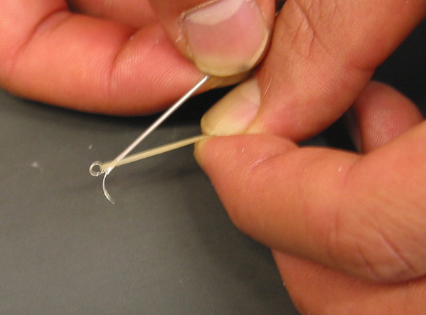
- suture needle toe with rubber band:
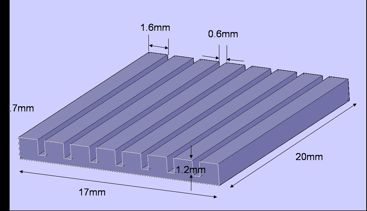
- polyurethane slider plate
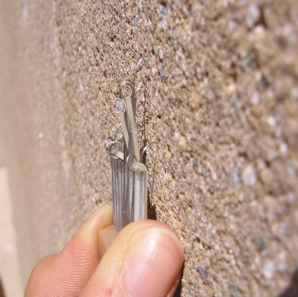
- foot on the wall:
Squirrel foot with plastic square tubes
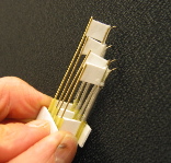
-- AlanAsbeck - 21 Jul 2004- Small version of squirrel foot with plastic tubes:
Springy toes with attach/detach tendons
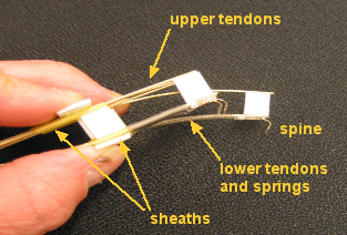
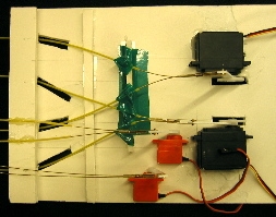
MarkCutkosky - 09, 13 July 04- See the ToyBot04 page for some videos of this design on an untethered RC toybot platform
Springy independent toes (squirrel foot) v.2
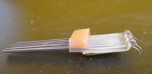
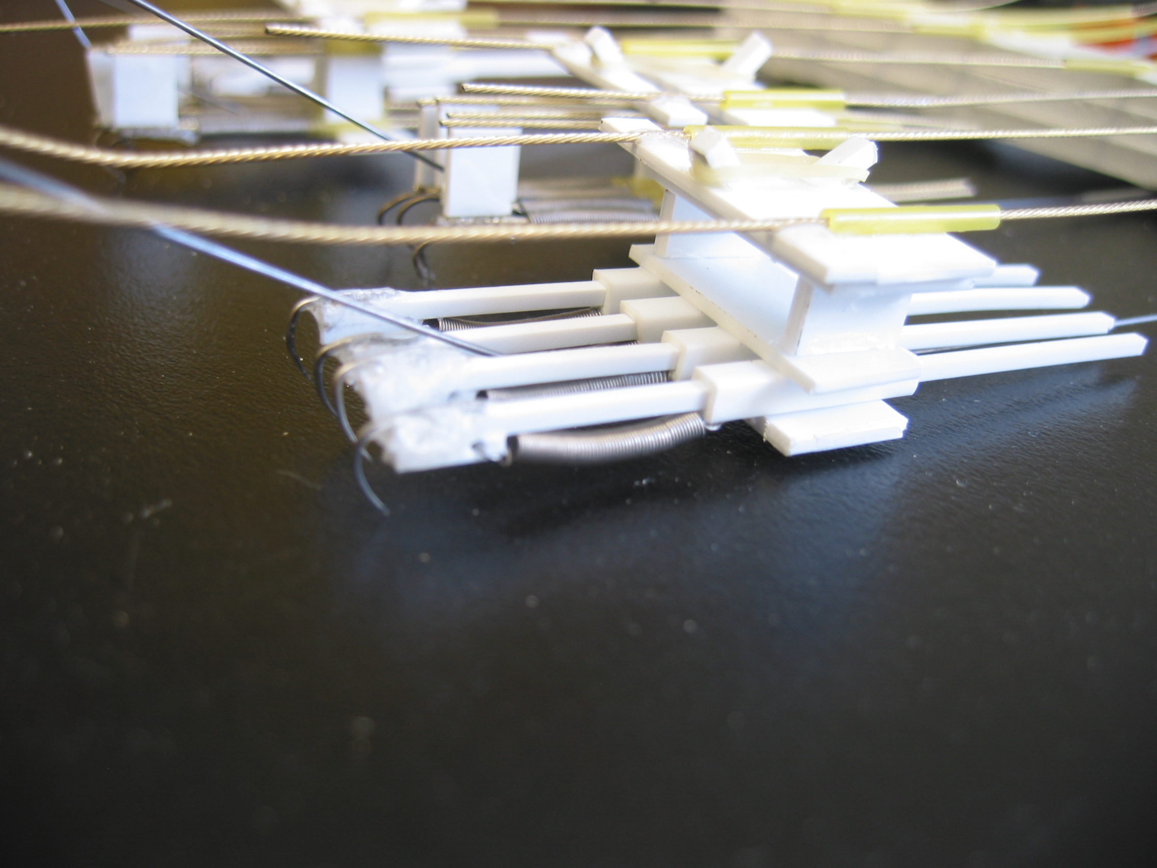
-- AlanAsbeck - 06 Jul 2004 A second prototype of the independent toes design was made, that would be robust enough to attach to the test track. This version also incorporated a sliding plate that went over the top of the toes, so that the compliance in the normal-to-the-wall direction could be adjusted as desired. If the plate was slid up, it pushed rigidly against the toes, so that they could dig in to a tree trunk. If the plate was slid back, the toes could push out of the way so that e.g. the footpad could stick to a smooth surface. This version worked better than the first one, possibly because the compliance with the plate slid down (i.e. at its softest) was slightly more than in the original design, which was quite floppy. It was quite heavy, however, due to all the brass tubes and plastic.- Squirrel Foot v.2, bottom view: (see bottom of page for full-sized image)
- Squirrel Foot v.2, claws digging in to tree trunk: (see bottom of page for full-sized image)
Independent pin array concept
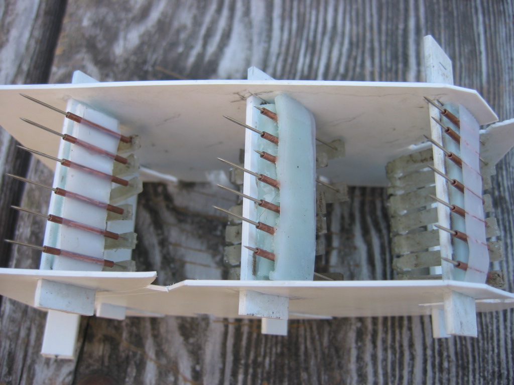
-- AlanAsbeck - 06 Jul 2004 The idea behind this foot was to have a large number of very sharp needles, and have them very compliant in the normal-to-the-wall direction, such that the foot would conform to the surface and that every needle would be touching the wall. Then, some needles would catch in little holes in the wall or other quite-solid toeholds, while the majority of the needles would touch the wall and bear a little of the load each, due to plain old friction. The angle of the needles would be kept approximately the same regardless of whether or not they were bearing a load. In this manner, hopefully a very good foothold could be obtained, because a very large number of needles would be touching the wall, which would provide lots of redundancy. In the first version, I used copper tubes to hold the needles at the desired angle, while providing a very weak spring mechanism at the back. The compliance for each pin was about what I wanted it to be, but the foot suffered from the problems of the pins getting stuck in the tubes (due to very small amounts of friction), so not all of the pins would touch the wall. Also, the angular compliance was much softer than it should have been, so that if a pin caught in a hole, the foot would slide down until it (usually) came out from the hole.- Alan's Independent Pins foot, v1 (with tubes): (see bottom of page for full-sized image)
- Alan's Independent Pins foot, v2 (4-bar linkages): (see bottom of page for full-sized image)
Load balancing conformal linkage
MotohideHatanaka June30, 2004 The two-layered coupled-parallelogram linkages are intended to balance loading on spines/claws/pads while conforming to surface geometry. The design was intended to conform to features distributed in a mostly even plane. Unexpectedly, because of the low torsional and shear stiffnesses of the flexures, the structure can also accomodate unevenness out of the plane. The load balancing seems to work well. Stiffnesses of the flexures must be tuned to achieve favorable deformation of the structure. (Most importantly, the smaller linkages are too stiff relative to the large linkage.) The entire structure can be supported by some buckling or dislocating structure that would prevent damage on the spines/claws. What is the desired deformation mode? This prototype was made of balsa wood and rubber strips. Manual labor approximately 4 hours. The design can easily be implemented to SDM fabrication.


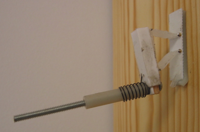
4-bar linkage concept
The idea behind this foot design is to use a 4-bar linkage to create a remote center of compliance at the wall surface. The 4-bar has an instantaneous center just inside the wall. The rationale for this is that ideally one would like a pivot right at the wall surface so that no unpeeling moments can be transmitted into the foot. This funky prototype is made of balsa wood, styrene and model airplane hinges. The whole foot is mounted on a swivel, or caster, consisting of a sleeve with a torsional spring. The "sole" of the foot is very sticky Urethane 10A.- 4bar linkage foot stuck on the wall (see bottom of page for full-sized image)
Springy load-sharing toes concept
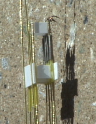
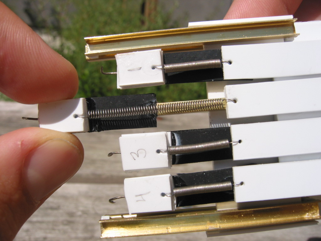
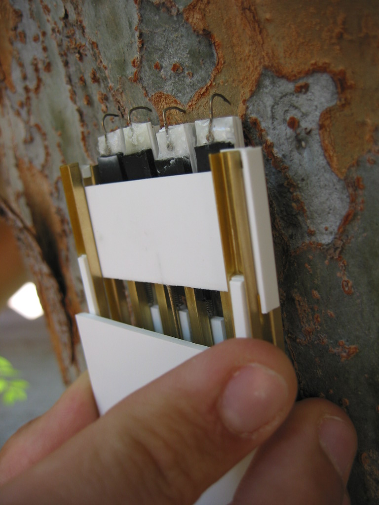
* Alan's v1 foot on MERL wall: (see bottom of page for full-sized image)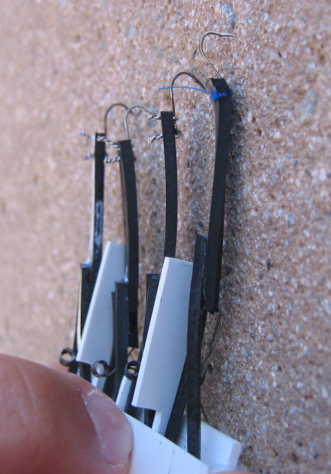 The foot works by allowing the toes to independently stretch along the length of the toe (axial direction). This enables the claws to scrape over a larger area of wall in search of a good toe-hold, since if one sticks, it stretches while the others continue to slide down the surface looking for a toe-hold. If multiple toes have found holds, then load is distributed so that each toe carries a smaller load--I think this makes the individual toes less likely to slip.
The current prototype is extremely compliant in the normal-to-the-wall direction, which allows the toes to move out of the way if the foot-pad needs to adhere to a smooth surface. The claws still grab the MERL wall even with this amount of compliance since the toe-holds are usually little holes in the wall which the claw can just slide into. However, on a smooth tree trunk the claws do not engage at all, since the tree is hard and they need to be preloaded to dig in to the tree. In the next version of this foot I think we will have an actuator so you can control the compliance of the toes in the normal-to-the-wall direction.
The foot works really well on rough surfaces like the MERL wall. When dragging the foot down the wall, often some of the claws will catch for a little bit, then release and spring back toward the foot with a high velocity. Having more damping in the axial direction would make these toes come back more slowly, which would make them more likely to catch I think. Usually, around 2-3 claws end up catching the wall, with most of the load taken up by one or two claws, and the others only weakly holding on. However, one of the claws will almost always find a good toe-hold.
The foot works by allowing the toes to independently stretch along the length of the toe (axial direction). This enables the claws to scrape over a larger area of wall in search of a good toe-hold, since if one sticks, it stretches while the others continue to slide down the surface looking for a toe-hold. If multiple toes have found holds, then load is distributed so that each toe carries a smaller load--I think this makes the individual toes less likely to slip.
The current prototype is extremely compliant in the normal-to-the-wall direction, which allows the toes to move out of the way if the foot-pad needs to adhere to a smooth surface. The claws still grab the MERL wall even with this amount of compliance since the toe-holds are usually little holes in the wall which the claw can just slide into. However, on a smooth tree trunk the claws do not engage at all, since the tree is hard and they need to be preloaded to dig in to the tree. In the next version of this foot I think we will have an actuator so you can control the compliance of the toes in the normal-to-the-wall direction.
The foot works really well on rough surfaces like the MERL wall. When dragging the foot down the wall, often some of the claws will catch for a little bit, then release and spring back toward the foot with a high velocity. Having more damping in the axial direction would make these toes come back more slowly, which would make them more likely to catch I think. Usually, around 2-3 claws end up catching the wall, with most of the load taken up by one or two claws, and the others only weakly holding on. However, one of the claws will almost always find a good toe-hold.
Passively Retracting Spines 1
MiguelPiedrahita - 24 Jun 2004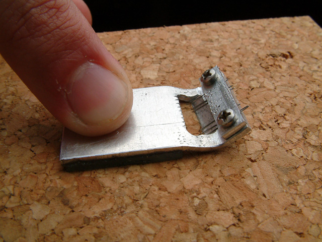
 This design uses a combination of micro-spines and a urethane friction pad to provide good performance on both smooth and soft surfaces. Several 0.2mm microspines provide traction on soft surfaces such as cork by digging into the surface. The way the spines are mounted allows them to easily deflect away from harder surfaces and allow the friction pad to come into good contact with the surface. This design does not work well on rough surfaces such as concrete because the spine tend to catch on to asperities and are quickly bent out of shape as the foot is pulled along the surfaces. This problem could be avoided by using larger spines mounted on torsion springs to provide the same desired compliance but with increased toughness.
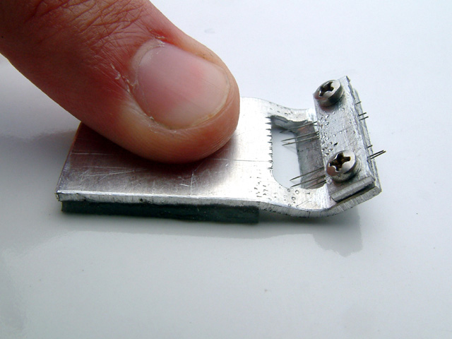
Passively Retracting Spines 2
MiguelPiedrahita - 24 Jun 2004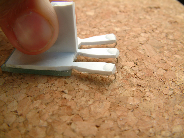
 This design also uses a combination of spines and a friction pad. The spines deflect when the foot is pressed on a hard surface, providing a passive "retraction". This foot works much better than the above design on rough surfaces, as the spines do not bend out of shape very easily. However, on rough surfaces only one of the spines generally engages the surface.
Rotational DOF For Multiple Claw Attachments 1
MiguelPiedrahita - 24 Jun 2004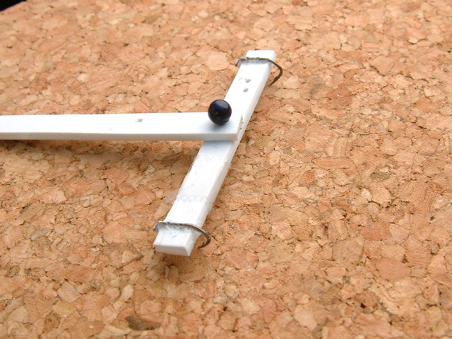
 This simple gizmo illustrates a principle which could be used to ensure the engagement of multiple claws/spines on a rough surface. As soon as one spine catches on the surfaces, the arm rotates until the second spine also catches on. A hierarchy of several levels of this mechanism could provide engagment for many spines. For example, the picture on the right shows a two-level implementation, which does a pretty good job of getting all four claws to engage.
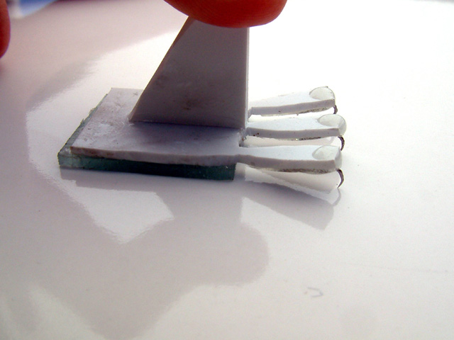
Rotational DOF For Multiple Claw Attachments 2
DanaUng - 28 July 2004
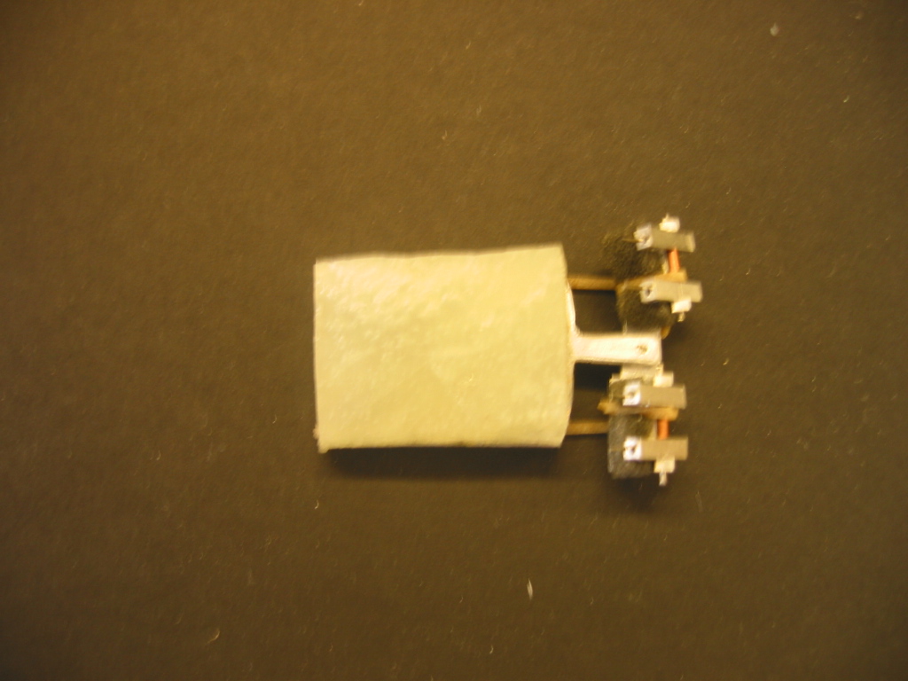 This foot design again allows for a larger claw search area by enabling the claws to rotate with respect to other claws that have engaged. These claws are also retractable to allow the urethane pad to contact smoother surfaces..
Retractable toe concept
This is a toe with a connection piece in the middle for side to side compliance. Several of these toes are to be aligned for a foot. The tip of the toe slide in and out of the piece its attached to and is held in place with a spring inside. The spring is in equilibrium when the claw is retracted (when the tip is pushed in) so force must be applied to pull out the claw. This is quite similar to Alan's springy toe concept. JiLee- Jun 24 2004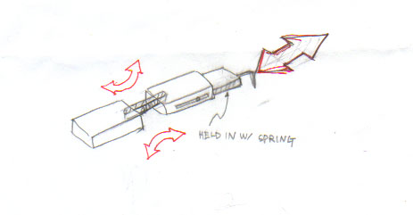
Wooden Foot
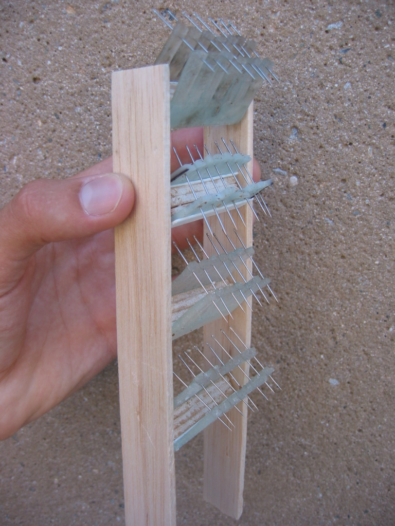
DanaUng - 27 July 2004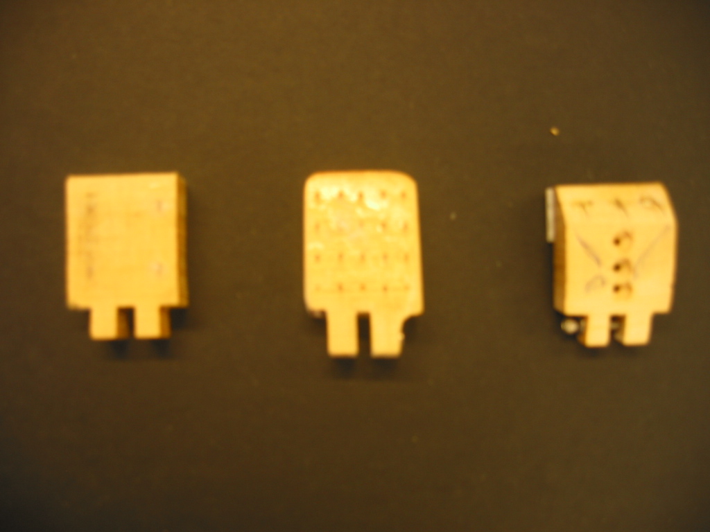
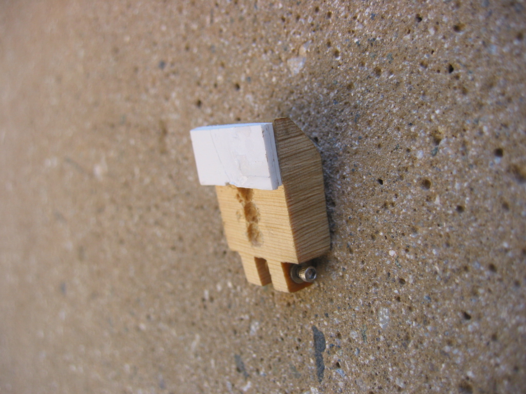
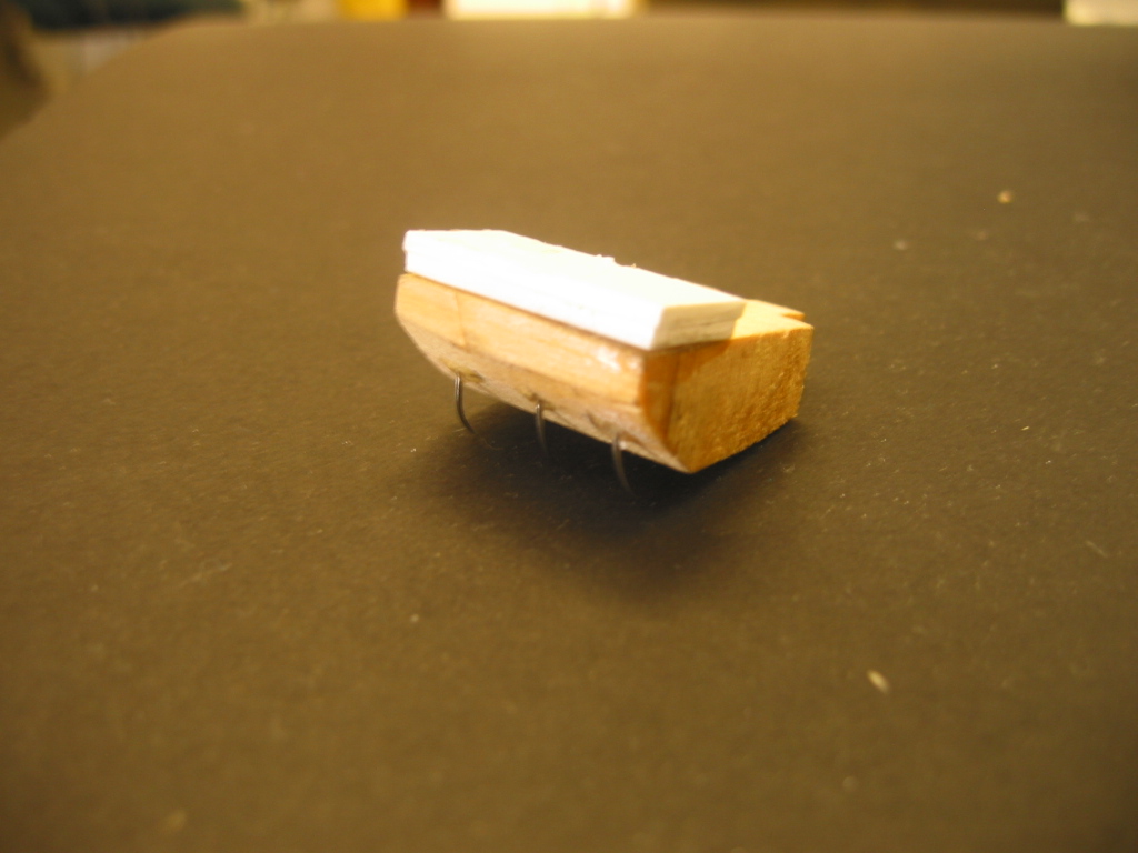
This wooden foot helped us quickly determine the optimum number of pins to use on the foot and to determine the orientation of the pins (i.e. curved, straight at a 45 degree angle). We found that a foot with more than 4 pins had trouble engaging because it required a high normal force.
Ideas, requests, problems regarding TWiki? Send feedback