new web: http://bdml.stanford.edu/pmwiki
TWiki > Rise Web>ClimbingRobot > ClimbingConcepts>EarlyFootDesigns (31 Jul 2010, DanAukes)
Early Foot Designs (Oct. 2003-Oct. 2004)
Put stuff in reverse chron. order (newest at top). %ENDCOMMENT%- See FootDesign for other foot designs.
Regarding Al's comments:
- I also observed the difference in stickiness with these feet. Not sure why, they are made out of the exact same polyrethane (20A shore hardness), so perhaps a slight difference in the resin/hardener ratio is at fault.
- The pads weren't crowned when I shipped them off. My guess is that the hard polyurethane wasn't fully cured when I superglued the sticky pads on, and the superglue added enough stiffnes on one side to introduce stresses during the curing which led to the deformation.
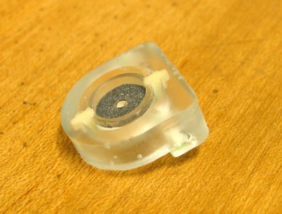
- Twine flexure will be replaced by ball joint on Sticky Foot v.2, which should be more robust and easier to manufacture. Test of method to ball joint manufacturing came out quite well, see picture above.
We have replaced the front feet on RiSE with the new v.1 feet. You can see a video of them in action here. Initial observations are that:
- The pad material seems less sticky than on the v.0 feet
- The pads seem to have been "crowned" in assembly or shipping. This results in relatively small contact area and slipping
- The "twine flexure" while not transmitting ANY peeling torques, does colapse all the time. I am unsure if this is a real problem, but there are now typically two point of contact between the "ankle" and "pad" resulting in the possability of generating peeling torques.
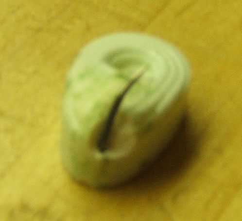
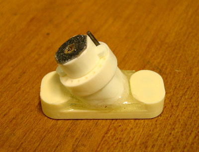
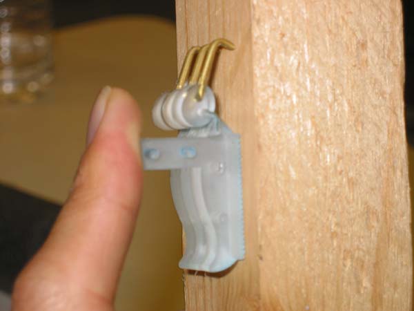
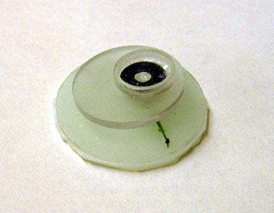 -- MiguelPiedrahita? - 08 Oct 2004 Sticky Feet v.0: Simple sticky-pad (soft polyurethane) prototypes have shown good performance on acrylic on the Stanford Test Track. The prototype shown below uses a soft polyurethane post to provide pitch, roll, and yaw compliance which allows the foot pad to easily align to the wall surface. A friction coefficient of approx. 3.5 has been measured on the test track (i.e. 3.5N of forward climbing force per 1N of normal force into the wall).
 The feet are made out of styrene plastic with a polyurethane flexure and sticky pad, all bonded with superglue. The feet mount to the same ankles as the spiny feet do. The front of the foot is the side with the flexure in it. The feet should be oriented such that at the beginning of the stride phase the feet are pointing straight ahead.
The feet will work best when they have a normal force into the wall, so mainly when climbing slopes of ~50deg or less. At higher angles, the front feet in particular will tend to peel from the front quite easily. If this occurs, spinning the feet 180deg so the flexure is in the back of the foot may help reduce the peeling tendency.
Trajectories: I had the most success with a very quick and late attachment, and a very quick and early detachment. In other words, slap the feet straight down and pull them straight up, and only use the straight part of the trajectory.
 -- AlRizzi? - 29 Sep 2004 Foot Failures Just two images of the failures we have had with the new feet. In these not-so-great pictures you can see how we have managed to "pull/wrench" the spines out of the foot. Of the three failures we have seen, two have resulted in the "toe" area of the foot breaking, the third failure involved a failure of one of the glue joints attaching the yaw flexure to the foot/lower-leg.
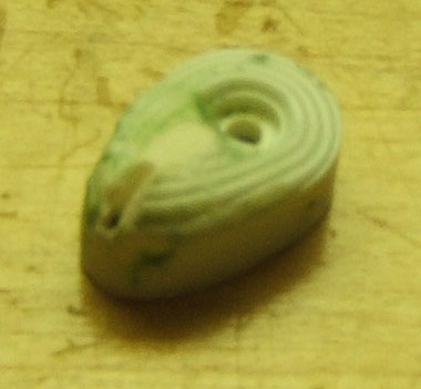
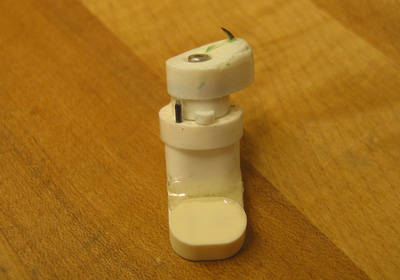
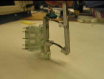
 -- MiguelPiedrahita? - 17 Sep 2004. New Feet consist of a single claw that is slightly angled towards the centerline of the robot to aid in detachment. This foot mounts on the same ankle shown below (10 Sep entry). Test track testing looks promising - very smooth attachment and detachment, generating climbing forces of ~10N and attachment force of ~3N.
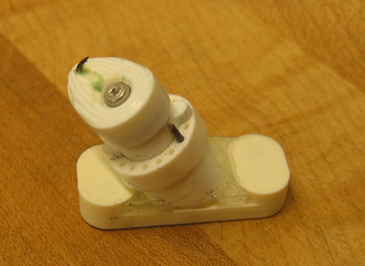
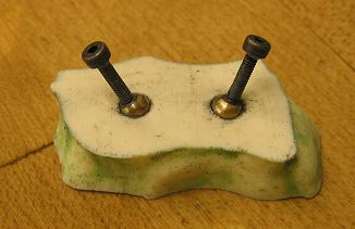
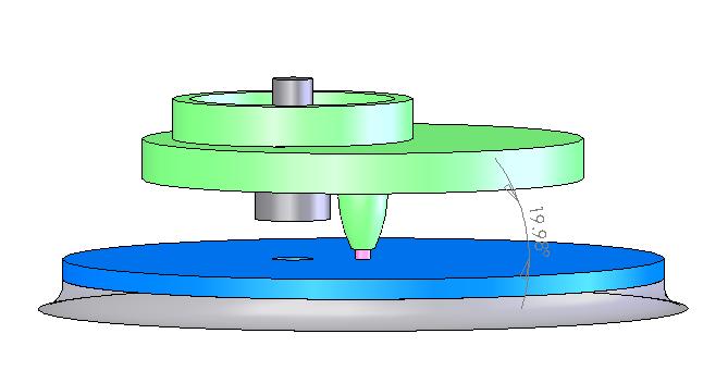
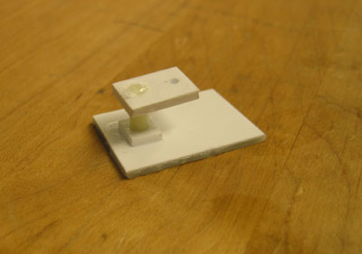
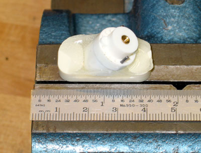
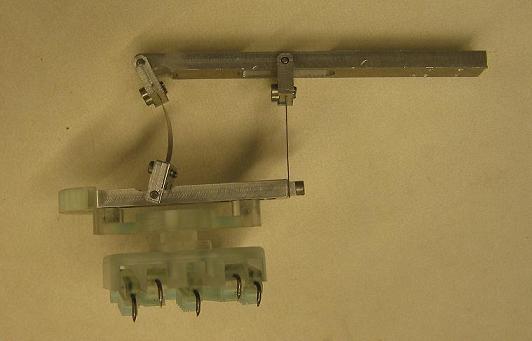
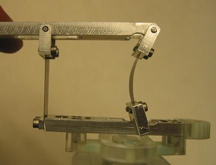
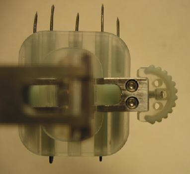
 -- MiguelPiedrahita? - 10 Sep 2004. New ankles and feet have been completed, see pictures below. The ankle provides yaw compliance through the use of a flexible polyurethane torsion rod, as in the July 2004 design. This ankle is much more robust than the July 2004 design because it does away with the flexures that allow for the canted mounting, which were the main source of failures. Instead, the ankle is canted at a fixed angle in the design of the rigid polyurethane.
 The foot mounts to the ankle with a sandpaper friction disc interface, as in the previous design.
The foot includes a roll flexure to allow the two claws to align to the surface.
Test track testing revealed some problems. The widely spaced claws lead to severe twisting of the foot about the yaw axis if only one claw engages the surface initially. This is exacerbated by the roll flexure, which is easily misaligned from the optimal vertical orientation, and thus results in the foot pitching back severely.
 -- MarkCutkosky - 24-26 Aug 04. Foot/leg interference problems discovered. Thinking about how to resolve it. - MiguelPiedrahita is back.
Revised version will be started while finishing the current one.
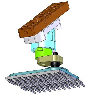
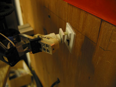
-- MarkCutkosky - 22 Aug 04. Moto's new ankles are in progress. See IMG_4610.JPG at bottom of page for status.
-- MotohideHatanaka? - 20 Aug 04
-- MarkCutkosky - 24-26 Aug 04. Foot/leg interference problems discovered. Thinking about how to resolve it. - MiguelPiedrahita is back.
Revised version will be started while finishing the current one.
-- MarkCutkosky - 22 Aug 04. Moto's new ankles are in progress. See IMG_4610.JPG at bottom of page for status.
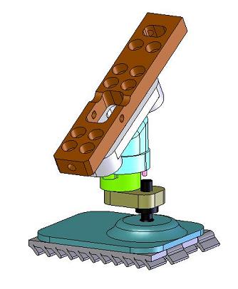
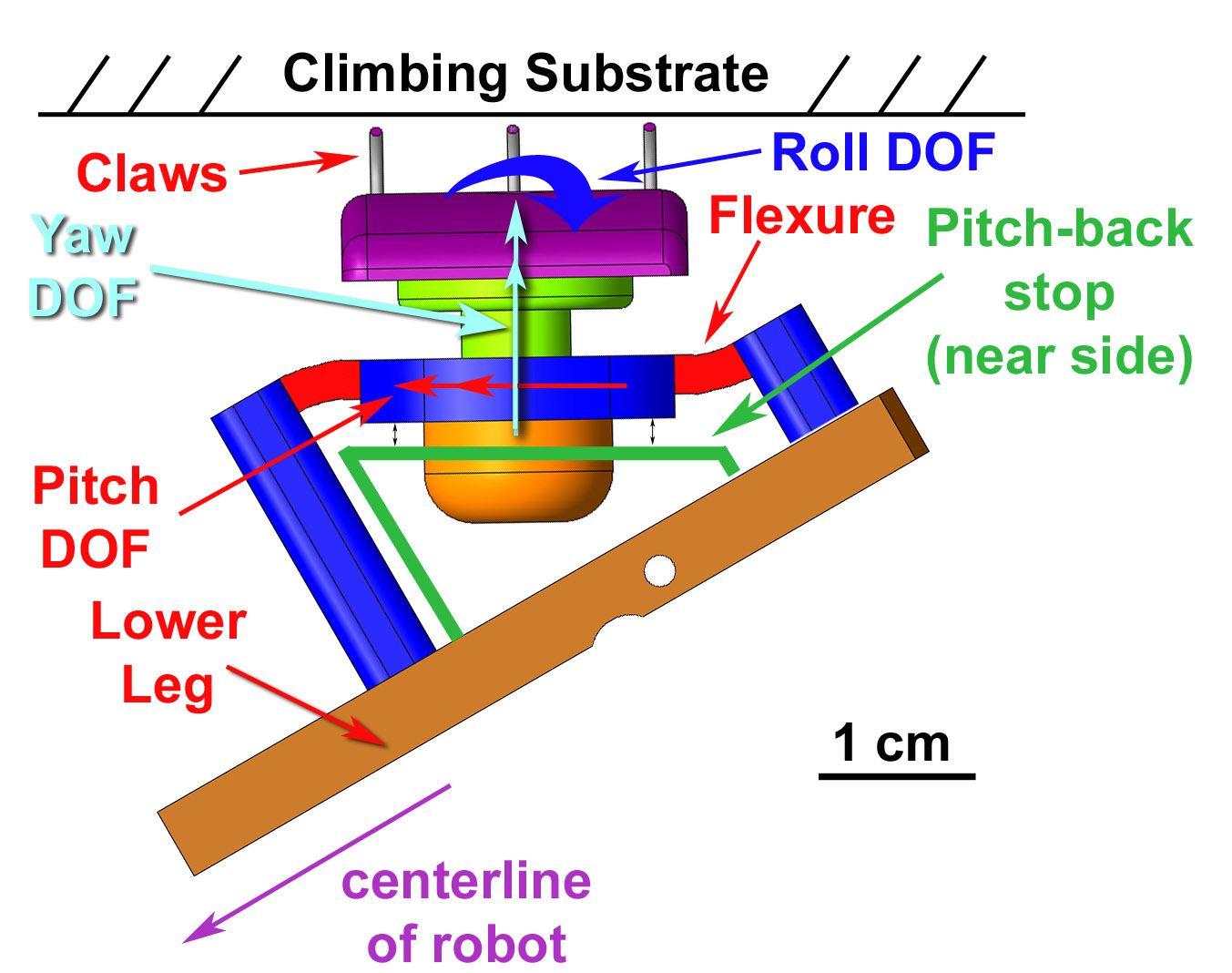
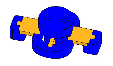
-- MotohideHatanaka? - 20 Aug 04 Ankle design for minimum pitching and limited yaw. Large version of this figure and Solid Works eDrawing file also available. (See bottom of page.)
- New foot/ankle design (July 04) is shown on the StanfordFootDesignTests page:
- Yardley_Products_INSERTS.txt: M2 inserts for feet and ankles (Yardley Products) -- WillP? - 01 Aug 04
- Yardley_Products_INSERTS.txt: M2 inserts for feet and ankles (Yardley Products) -- WillP? - 01 Aug 04
Quick prototypes from June 04 sumamarized in NewFootDesignsJune04 MiguelPiedrahita - 16 Jun 2004
Some thoughts on the path forward for the "official" RiSE climbing feet are discussed in this Powerpoint presentation: FootDesign-retreatslides.ppt. Some of the key points discussed include:
- Need functional feet for demos in August/October
- 3 types of surfaces to consider: Rough (concrete, hard wood); Soft (corkboard); Smooth (glass, metal)
- Is actuation needed or can a single passive design work on all three types of surfaces?
Decided that we would work in parallel on two kinds of feet:
- Next generation official running/climbing foot for the RiSE platform. This page (below) concerns the evolution of the official RiSE feet.
- Some more radical feet aimed specifically at vertical climbing on non-soft surfaces (e.g. rough concrete, hardwood, drywall... -- whatever we can get "interesting" performance on). Creating a couple of new TWiki pages for these feet:
- CompliantSpinedFoot?
- CompliantStickyFoot
- ActivePeelingFinger?
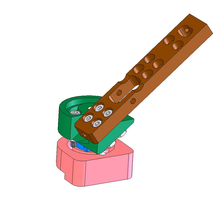
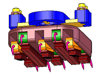
4th generation foot design is shown here. This design includes a modular "ankle" flexure (blue in figures below) which provides the desired compliance to the foot. The disk interface between the foot and ankle allows for adjustment of the nominal yaw orientation of the foot. This foot design has five toes, two of which are rigid and three are sprung.
For photos of the processes used to manufacture this design, see FootFab.
 |
 |
| Bottom View | ankle flexure |
|---|---|
 |
 |
| Lower part of coupler with climbing/running foot & 2-D flexure | 2-D flexure |
 |
 |
| Running foot | Video(Click to watch) |
 |
|
| lower leg video(Click to watch) |
Hummingbird Foot designed and manufactured by MotohideHatanaka, more information at HummingbirdFoot.
 Third generation sticky feet designed and fabricated by MiguelPiedrahita.
 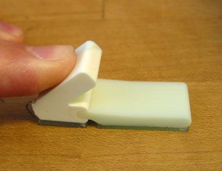 MiguelPiedrahita 10-17-03
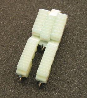
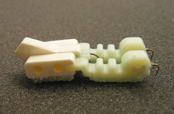
 Second generation sticky feet designed by WillP and fabricated by MiguelPiedrahita. These feet consist of three individual planar parts: the ankle and the two toes. These parts are fabricated independently and then assembled with two pins (or superglue in this case!).
Each of these components has a fish hook embedded in the end to act as a claw. The toes are fabricated from a medium-soft urethane, which provides compliance along the entire toe. All contact surfaces are covered with a "tread" of very soft urethane for high local compliance. This urethane is also relatively tacky, and sticks quite well to many surfaces until it gets dirty.
When dragging the foot along a surface, the compliant toe tends to pitch upwards, thus reducing the contact pressure along the toe and allowing it to slide quite easily. The next foot iteration will try to address this by moving the location of the ankle such that the pressure along the toe stays more evenly distributed (i.e. an ankle placed further forward).
 |
 |
 |
| 2nd generation sticky feet - bottom | 2nd generation sticky feet - side view | 2nd generation sticky foot climbing wall |
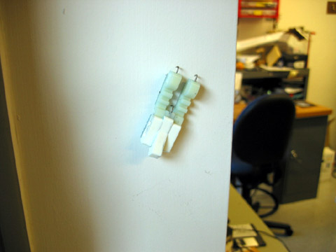
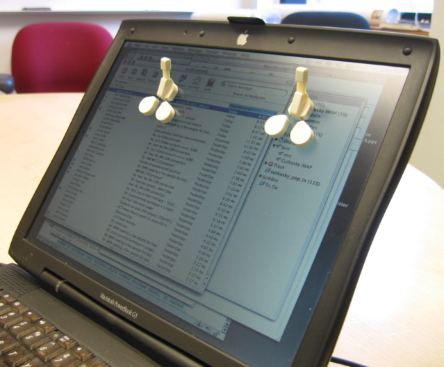
First generation sticky feet fabricated by WillP. These ones have pads of soft urethane embedded within "toes" of stiffer urethane. Small spring steel wires provide toe compliance. A medium-soft urethane flexure provides compliance at the ankle. The design is very similar to the concept shown at the RiSE August kickoff meeting. Here's a picture of them sticking to the LCD panel of my laptop:
- 1st generation sticky feet climbing on my laptop:
Ideas, requests, problems regarding TWiki? Send feedback