Violeta Crow
Summer Projects
This is my new page from July 6 onward. Older stuff (before July 6)
July 6, 2011: Back to Electroosmotic Pump
- Kim's presentation about Adhesion and NEMS relays
- Advantages of biomimetic adhesion for robots:
- Adhesion to smooth and rough surfaces.
- Passive adhesion.
- Non-fouling.
- Low attachment and detachment forces.
- Dry Adhesive:
- Geckos, spiders.
- Van der Waals forces.
- Best on smooth, dry surfaces.
- Wet Adhesive:
- Frogs, ants, beetles.
- Van der Waals, capillary, and viscous forces.
- Best on dry or wet smooth surfaces.
- Gecko Inspired Adhesion:
- Features branch out.
- Directional.
- Frog Inspired Adhesion:
- Features allow fluid to move away from contact area.
- Capillarity pulls it into surface.
- Sets after liquid has moved away.
- Advantages of biomimetic adhesion for robots:
- Worked on putting together electroosmotic pump
- Laser cut new acrylic pieces for the frame because one of the previous ones snapped and the other one did not align correctly with the electrodes.
- Thickest piece of acrylic available was 3mm thick.
- Tried to drill holes 2mm wide but acrylic snapped in the process.
- Tried to make new pieces but the laser cutter was down for the day.
- Made more sealing rings using Sil-poxy.
- Laser cut new acrylic pieces for the frame because one of the previous ones snapped and the other one did not align correctly with the electrodes.
July 7, 2011: Electroosmosis
- Meeting:
- Get cool pictures of WetAdhesion for Website.
- Use ABS instead of acrylic to make pump.
- Find out more detailed specs for pump:
- Thickness of glass
- Pumping rate
- Importance of material - can we use ceramic, polycarbonate, or urethane instead of glass?
- Something to try with rigid backing: Embed a thin, flexible fabric (ie. carbon veil).
- Make a "handle" by putting some fabric horizontally across pad.
- Detach by pulling from the corner
- Literature review - check references to understand electroosmosis better.
- Went to TAP Plastics to buy new material for pump.
July 8, 2011: Arduino
- Arduino Tutorial:
- Using RBBB (Rally Bare Bones Board) which is Arduino IDE compatible.
- When connecting diodes, short leg (cathode) goes to ground.
- Pin 13 already has a resistor and is connected to an LED (in most Arduino boards).
- Program divides into two main parts: void setup() and void loop().
- For sensors, use voltage dividers. Changing R1 will produce a change in Vout.
- If necessary, use analog pins as digital pins, but not vice versa.
- Always set pinMode to ensure correct functionality.
- Lab Meeting: Barrett's presentation on skin for sensing project.
- Used the laser cutter to make pump frame on ABS.
- Some sections were not cut all the way through. Another pass was necessary, but the laser cutter was no longer available because a class was about to start.
- Spent the rest of the afternoon cutting the frame by hand.
July 11, 2011: (Hopefully) Finish Pump
- Drilled 1/16inch wide channels on new frame.
- Checked if all the components fit together. Sealing rings were not wide enough.
- Fixed old sealing rings and made two more.
- After cutting my finger with one of the aluminum pieces I decided to spend some more time filing down the edges of both electrodes.
- Drilled and tapped holes on frame pieces to attach electrodes using 8 32 1/4 screws.
- Went to the physics store to get more screws.
July 14, 2011: Put Together Pump
- Sealing rings had adhered together and broke when trying to pull the pieces apart.
- Made new sealing rings and waited for glue to cure before proceeding.
- Put all the pieces together and sealed spaces with Sil-poxy.
- Put hoses in lateral openings and used Sil-poxy to hold them in place.
- Need 15V power supply and wires
July 15, 2011: Debugging Pump
- Attached needles to hoses and used a 20ml syringe to put water inside pump.
- Water leaks at the bottom.
- Spent all day trying to find leak and replace the sealing ring that is causing the problem.
- Each time the pump is disassembled the rings stretch or break.
- Decided to take everything apart and redo all the sealing rings (on Monday).
- Water leaks at the bottom.
- Meeting: Samson's Greenlight presentation and Barrett's update.
July 18, 2011: Still working on Pump
- Removed all sealing rings to start over.
- Used Sil-poxy to seal electrodes in place.
- Used RTV 108 Translucent Adhesive to make sealing rings for glass.
- Lesson learned from making pump: expect that everything that can go wrong will go wrong.
- (Some) Problems faced while making pump:
- Acrylic snapped while drilling holes.
- Laser cutter did not cut ABS all the way through and frame had to be cut by hand.
- Aluminum electrodes were too big for the frame and had to be filed down thoroughly.
- Shipment of fritted disk was late.
- Shipment of o-rings was incorrect and sealing rings had to be handmade.
- Sealing rings had to be redone several times.
- When pump was about to be tested, a leak was found and the sealing rings had to be replaced again.
- Shipment of o-rings finally arrived. Rings slipped out of place when trying to close the pump. Sil-poxy was used to keep rings in place.
- Surrounded the disk with 5 o-rings to force water to go through the channels and not around the disk.
July 19, 2011: Fixing Leaks
- Filled pump with water and realized that water was leaking from one of the sides.
- Unscrewed the electrode to fix sealing.
- I was too eager to finally test the pump so I did not allow enough time for the sil-poxy to cure before I filled it with water again. Needless to say, it started leaking again.
- Repeated the process a couple times. Decided to put an additional outer sealing ring and wait for at least half an hour for the sil-poxy to dry before trying again.
- Filled pump again - no leaks.
- Installed LabView in the computer in MERL 126.
- Started setting up myDAQ to use it as a 15V power supply.
July 20, 2011: Sensor Tests
- Checked circuit to test sensor.
- Labeled all the wires coming from the myDAQ.
- Set up the power supply based on pictures from the last time the circuit was used.
- Modified LabVIEW program to read only from input AI0 and save it to a file with a different name every time the program runs.
- Modified Matlab program to only display the sensor output in the time range specified by the user.
- FFT and EFT are not needed.
- Ran "grasping" tests with three different objects (small wrench, green pen, black pen) and went back to Merl 132 to verify the data with the Matlab program (Matlab is not installed in the computers in Merl 126).
- Each test consisted of lightly touching the center of the sensor with the object three times. Pictures were taken to record the positioning of the objects on the sensor.
- Ran additional tests with the following objects: full water bottle, bottle cap, mouse, right click of a mouse, syringe, small screw driver, and a business card.
- Connected wires to electrodes. Checked voltage from power supply using the myDAQ as a multimeter.
- Pump was filled with water, but it started leaking again before it could be tested.
- Pump was taken apart. The sealing rings had slipped out of place.
- Used RTV 108 to reinforce sealing and will let dry thoroughly before closing pump again.
- Will look into other designs involving arrays of droplets.
July 21, 2011: Pump (sort of) Works!!
- Tested pump again:
- Filled with about 30mL of tap water.
- No more leaks were found.
- Power was drawn from the rails of a protoboard already setup for previous sensor tests.
- Protoboard was connected to a positive voltage supply, a negative supply, and ground.
- One of the electrodes was connected to ground and the other one was alternately connected to positive and negative supply to generate a pulse signal.
- Electrodes were identified by colored marks (Orange or black).
- Test sequence:
- Applied +10V to orange electrode -> Droplet surfaced on orange side.
- 0V -> No change.
- -10V -> Volume of droplet in orange side decreased. Volume in black side increased.
- Cycle continues as signal pulses.
- Observations:
- Water continues flowing and it gets to a point in which droplets can't retract anymore and eventually burst.
- Flow rate does not seem to be as fast as in Steen's video.
- Changed voltage to 15V -> Same response.
- Ran test again to take video -> Only droplet in orange side surfaces, regardless of the polarity of the voltage.
- Checked voltaqges using the myDAQ multimeter.
- Switched wires around in different combinations: Black electrode to ground, one electrode to -V and the other one to +V, and vice versa. Final configuration was black to ground and orange to -V.
- Removed excess water.
- Let the system rest for a few minutes.
- Pump started working again and I recorded it (I'm not sure of what the problem was).
- Summary of materials used:
- Power supply: 6237B Triple Output Power Supply Hewlett Packard.
- 2 protoboards and assorted wires.
- Pump:
- Black ABS.
- 2 Aluminum electrodes.
- 1 glass frit (50mm dia, 3.75mm thick).
- 5 sealing rings.
- 4 screws and nuts to clamp.
- 8 screws for electrodes (8 32 1/2).
- 2 syringes (20ml and 3ml).
- myDAQ multimeter.
- Distiled water.
- Steen, Paul H., and Michael J. Vogel. "Capillarity-based Switchable Adhesion." Proc Natl Acad Sci U S A, 3 Feb. 2010. Web. 21 July 2011. <http://www.ncbi.nlm.nih.gov/pmc/articles/PMC2840443/>.
- Reviewed paper to make different pump concept: SECAD = Switchable electronically-controlled Capillary Adhesion Device.
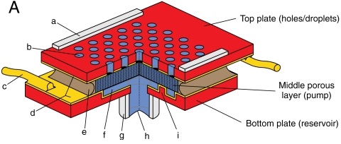
- Notes on Machine Shop device manufacturing:
- Assembled with several rubber gaskets and clamped together with screws.
- Droplet-to-droplet fluid communication must travel thru flow-restricting porous pump layer.
- Eliminate any gaps between pump and top plate by sanding the top layer of the glass frit.
- Rubber gaskets and top electrode have identical hole patterns to top plate. Align carefully when assembling.
- Order of assembly: Top plate, gasket, electrode plate, gasket, pump surrounded along sides by gasket, electrode, gasket, bottom plate / reservoir.
- Device characteristics:
- Area of hole arrays: 15mm x 15mm.
- Top plate thickness: 3mm.
- Pumping layer thickness: 4mm.
- Bottom layer: 25mm.
- Number of holes (N): 100-4876.
- Tightest hole packing tested (phi): 0.4.
- Spacers: 25-60 um thick
- Use tape or shim stock around perimeter of top plate
- C (0.025mm), D (0.04mm), or E (0.05mm) from pack of shim stock available in the lab.
- Designed bottom layer to be laser cut on acrylic.
July 22, 2011: Design of New Pump (SECAD)
- Laser cut acrylic to make bottom layer of pump:
- 2mm thick black acrylic to make 2.2" by 2.2" square to serve as base.
- 1mm diameter hole in the center to connect to hose.
- 5mm thick clear acrylic to make square of the same dimensions with a 5cm diameter circular cutout in the center to serve as reservoir.
- Five 2mm diameter cylindrical posts to support glass frit above reservoir.
- 2mm thick black acrylic to make 2.2" by 2.2" square to serve as base.
- Put together bottom layer using acrylic cement.
- Posts were attached to base in a circuilar pattern, equally spaced from the edge and the center of the circular cutout.
- Lab meeting: Eric's Quals presentation on Friction
- Design of top layer: Make holes as small and tightly packed as possible. Michela has been working on something similar. She gave me her notes on how to make small holes with the laser cutter:
- Use "raster" instead of vector.
- Use "low res" setting
- Draw a shape and fill it (color corresponds to the value of K).
- Select "no outline".
- Print using the following settings:
| Speed | Power | DPI | K | Focus | Result | |
| 1 | 10% | 100% | 75 | 30 | Normal | Didn't punch through. Some holes are ovals, others circles. |
| 2 | 5% | 100% | 75 | 30 | Normal | Many ovals. Most holes broke through. |
| 3 | 5% | 90% | 75 | 30 | Normal | Circular holes. Punched through. |
| 4 | 7% | 80% | 75 | 30 | Normal | Circular holes. Didn't punch through. |
| 5 | 7% | 70% | 75 | 30 | Normal | Circular holes. Didn't punch through. |
| 6 | 7% | 60% | 75 | 30 | Normal | Circular holes. Didn't punch through. |
| 7 | 7% | 50% | 75 | 30 | Normal | Circular holes. Didn't punch through. |
- Tried to make a circle 5cm diameter filled with holes using the orange shim stock (0.75mm thick) using setting 2.
- Holes did not punch through in the first pass.
- Tried doing a second pass, but had to stop it early because the plastic was bending and moving around.
July 25, 2011: Top Layer
- Tried to make another circle using setting 3.
- Holes did not get through and plastic deformed.
- Tried using 1/16" acrylic to prevent the plastic from bending.
- Did two passes, but the acrylic was barely engraved and none of the holes went through.
- Tried using CorelDraw to fill the circle with small circles (0.001mm)
- Used Edit -> Step and Repeat to fill the circle using offset of 0.006".
- Program crashed multiple times because of the complexity of the drawing. Had to start over several times.
- Tested cutting only a few rows of dots on acrylic - holes did not go through and were too close to each other.
- Possible solutions:
- Make dots bigger and more spread out.
- Try thicker material.
- Tape shim stock to a thicker material.
- Reduce power.
- Do several passes.
- Use separate files for each section so the program doesn't crash.
- Couldn't test other options because someone else needed to use the laser cutter.
- Tried using the computer in the lab to make the individual files but the version of CorelDraw is outdated and it doesn't have the Step and Repeat tool.
- Used one of the computers in the LFL to make 9 files with separate sections of the circle.
July 26, 2011: Top and Bottom Layers
- Tested first section on a piece of orange shim stock.
- Settings:
- Speed: 5%
- Power: 50%
- Frequency: 3400Hz
- DPI: 1200
- First attempt was not successful because the plastic melted.
- Deleted every other row of dots to space them out -> Produced good results.
- Settings:
- Lab tour for other SURF students.
- Fixed 9 files previously done to space out holes by deleting every other row.
- Cut base layers again to insert electrode before gluing.
- Cut two thin layers because there wasn't any thick acrylic available.
- Cut circles of different thicknesses to make posts to support disk.
- Laser cut orange shim stock section by section.
- Some rectangular sections did not get perforated.
- Only the first two sections of the circle were perforated as desired. The rest of the rows seem thicker and more spaced out.
- The material still deformed slightly.
July 27, 2011: Top and Bottom Layers Again
- Put together bottom layer embedding the wire mesh.
- Glued acrylic cylinders on top of mesh to support disk.
- Specs: 80 Mesh 0.0055" WIRE. 0.0070" OPG 31.4% OA.
- Put a coat of sil-poxy around disk and inserted it into the acrylic frame.
- Top layer needed to be redone before proceeding:
- Tried to fix issue of large sections of holes being skipped by the laser cutter.
- Decided to try rastering method again on thinner materials
- Obtained an acceptable piece by doing two passes on white material, but the plastic still warped.
- Tried to flatten the plastic by putting it on the hot plate and then between two flat metal surfaces -> melted
- Practiced flattening unusable pieces, but none of them became perfectly flat.
- Tried to cut more pieces on yellow and white material but encountered some alignment issues.
- Obtained one acceptable piece on white material and tried flattening it again, but faced some issues.
July 28, 2011: Putting Everything Together
- Tried flattening piece obtained yesterday but it ended up melting and deforming.
- Segmented circle into four sections before printing it to try to reduce warping.
- Issue -> Produced a slight misalignment at the center.
- Cut several pieces on materials of different thicknesses: two passes for black and yellow and one pass for blue and tan.
- Held material in place by putting it on top of a flat piece of plastic and and putting a frame and a weight on top of it.
- Prevented plastic from bending too much and getting caught in the moving piece.
- Best piece obtained: Blue (0.005")
- Held material in place by putting it on top of a flat piece of plastic and and putting a frame and a weight on top of it.
- Tried gluing the top electrode to the frame with super glue but it came off. Used sil-poxy instead.
- Specs: 150 Mesh 0.0025 WIRE. 0.0041" OPG 37.4% OA.
- Used super glue to attach the top layer and the spacers.
- Thickness of spacers: 0.0015"
- Glue: Tower Hobbies, Thin CA. Build-it (TOWR3800)
- Tested pump:
- Water seemed to be pulled up to the wire mesh, but did not get all the way to the top layer.
- Tried changing voltage and polarity, but there was no apparent change.
- Placed a glass on top of it to try to observe the flow of water (out or in, depending on the polarity of the voltage applied).
- Water seemed to be flowing out, probably due to capillarity, but not due to electro-osmosis because it did not flow back in after reversing the polarity of the voltage.
- Prepared presentation.
July 29, 2011: Presentation
- Revised presentation, got videos and papers ready and practiced a couple times.
- BDML bbq!
- Kim and I presented our work at the meeting. Kim gave an update on the prototypes she has been working on and I talked about electro-osmosis and described the devices I put together.
- The top layer of the SECAD will be replaced by a perforated brass sheet to avoid the issue of channel misalignment.
- John told us how to use his program for the CNC machine to make patterns of tiny holes.
- A sheet of perforated steel was ordered from McMaster
- Material Type: Stainless Steel
- Stainless Steel Type: Type 316
- Form: Round Hole Perforated Sheet
- Shape: Sheets
- Opening Pattern: Staggered
- General Opening Size: Extra Fine
- Micron Rating: 152 Microns
- Hole Diameter: 0.006"
- Percentage of Open Area: 27
- Center-to-Center Spacing: 0.0112"
- Thickness: 0.005"
- Gauge: 42
- Matt tried to help me perforate a sheet of brass using the Levil.
- We had some issues finding the right tool and placing it in the machine.
August 1, 2011: SECAD 2.0
- Took apart old pump to reuse glass frit.
- Cut frame on acrylic using laser cutter.
- Put everything together:
- Used super glue to attach the bottom electrode (brass sheet) to the base and top electrode (perforated steel sheet) on top of the glass frit.
- Overlapped three layers of acrylic to make the reservoir deep enough.
- Filled it with water to find leaks.
- Used sil-poxy around the edges to seal the device.
- Will let it dry overnight and test it tomorrow.
August 2, 2011: Test SECAD
- Unable to test it in the morning because I kept finding leaks.
- Tested pump: unsuccessful.
- Issue 1: Reservoir cannot be completely filled with water because of air bubbles.
- Possible solution 1: Relocate hole to introduce water from one of the sides. (Attempted -> unsuccessful)
- Possible solution 2: Remove plunger from syringe and try to level out pressure. (Attempted -> unsuccessful)
- Issue 2: Glass frit is not completely in contact with perforated sheet.
- Issue 3: Edges of glass are not sealed and let water through more easily.
- Possible solution: Substitute one layer of acrylic by a layer of sealant.
- Issue 1: Reservoir cannot be completely filled with water because of air bubbles.
August 10, 2011: Make SECAD work
- Came back to test SECAD again and try to make it work before wrapping up for the summer.
- Filled reservoir with distilled water through the hole close to the edge.
- Hole at the center was left uncovered to let bubbles out until the water reached that level. Used my finger to cover the hole from then on.
- No bubbles seemed to remain in the reservoir.
- Connections:
- Yellow wire from "COM" (ground) to bottom electrode.
- Red wire from "+20V" or "-20V" to top electrode.
- Actual voltages applied (measured with myDAQ Digital Multimeter): +22.5V and -23.1V
- Initially applying 15V. No response could be accurately observed. Some droplets seemed to surface and retract, but it was not clear enough to see on video.
- Applied pressure on top plate to improve the contact between the electrode and the disk.
- Used a needle to apply pressure without blocking holes -> produced observable results.
- 2 different behaviors were observed:
- Droplets on the bottom half of the circle surfaced when a negative voltage was applied and retracted with positive voltage. Droplets in the top half of the circle surfaced with positive voltage and retracted with negative voltage.
- Droplets all over the plate retracted with positive voltage and surfaced with negative voltage.
- Other observations:
- Droplets clump together into larger droplets
- Holes might be too close together.
- Water only surfaces at certain sections of the pump, not uniformly across the plate.
- Some sections of the disk might be blocked by dirt or glue.
- There are still some leaks in the frame.
- Switching occurs quickly (like in EO pump)
- Droplets clump together into larger droplets
- Unable to test if pump can hold its own weight because the needle being used to apply pressure prevents the to surface from making complete contact with the surface being adhered to.
- Filled reservoir with distilled water through the hole close to the edge.
Page last modified on June 15, 2012, at 11:25 am