new web: http://bdml.stanford.edu/pmwiki
TWiki > Courses Web>PreparationsForME310>PaperRobot2012 (08 Jul 2011, KellyJohnson)
p.bot -- A paper robot
Definition
What is the minimal definition of a robot? How about: a computer-controlled system that can (i) sense something (ii) communicate and (iii) produce some physical action. This very broad definition is also pretty much what electromechanical prototypes in ME310 are about. Therefore, your "paper bike" challenge to kick off ME310b is the Paper Robot: p.bot
The specific challenge to kick off ME310b is to create an Universal Agent p.bot that can send and receive messages with others of its kind using a standard protocol. The basic requirements are:
1. Use "sensors" (of any kind, including switches) to detect an input state that is imparted to the p.bot by a naive human user.
2. Communicate with others of its kind in a predefined standard format and protocol. In this activity, you will be using a software serial library, which simulates UART communication on standard digital pins.
3. Interpret received messages and do something physical to reflect the received messages as output that naive users can recognize and enjoy.
Constraints and Logistics
Stanford teams will be provided with a basic kit consisting of an Arduino equivalent (Really Bare Bones Board - RBBB, Modern Devices) microprocessor prototyping board and some accoutrements. The kit supports simple code development on Windows, Macintosh and Linux and has provisions for communicating, for controlling RC servo motors, lights, relays, etc., and for monitoring analog and digital input lines connected to switches, potentiometers, etc.
The p.bot systems need to be able to send and receive messages in a standard format, using the NewSoftwareSerial? library.
Communication and Connections
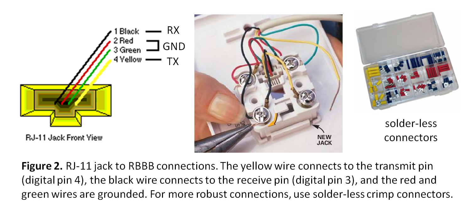
We will implement the software serial functions in order to pass information between the paper robots according to a standard protocol for the whole class. Everyone will use the same pins for receiving and transmitting data (digital pin 3 and 4) at a baud rate of 9600. Each robot will have an RJ-11 jack (for 4-wire telephone cables) attached.
You may wonder, Why not use the onboard RX and TX pins for communication? The answer: the RBBB, and most of the Arduino boards (Uno, Duemillanove, Fio, Mini, etc.) have one dedicated UART connection. This means, if you want to connect an FDTI USB cable between your board and the computer for debugging, you will not be able to use the onboard RX and TX pins for transmitting and receiving data between two robots while sending data to the computer at the exact same time. The Arduino Mega 2560 on the other hand, has 4 UART ports, so multiple serial connections are possible without the use of the software serial library. However, due to cost and size restrictions, we are using the smaller, RBBB board.
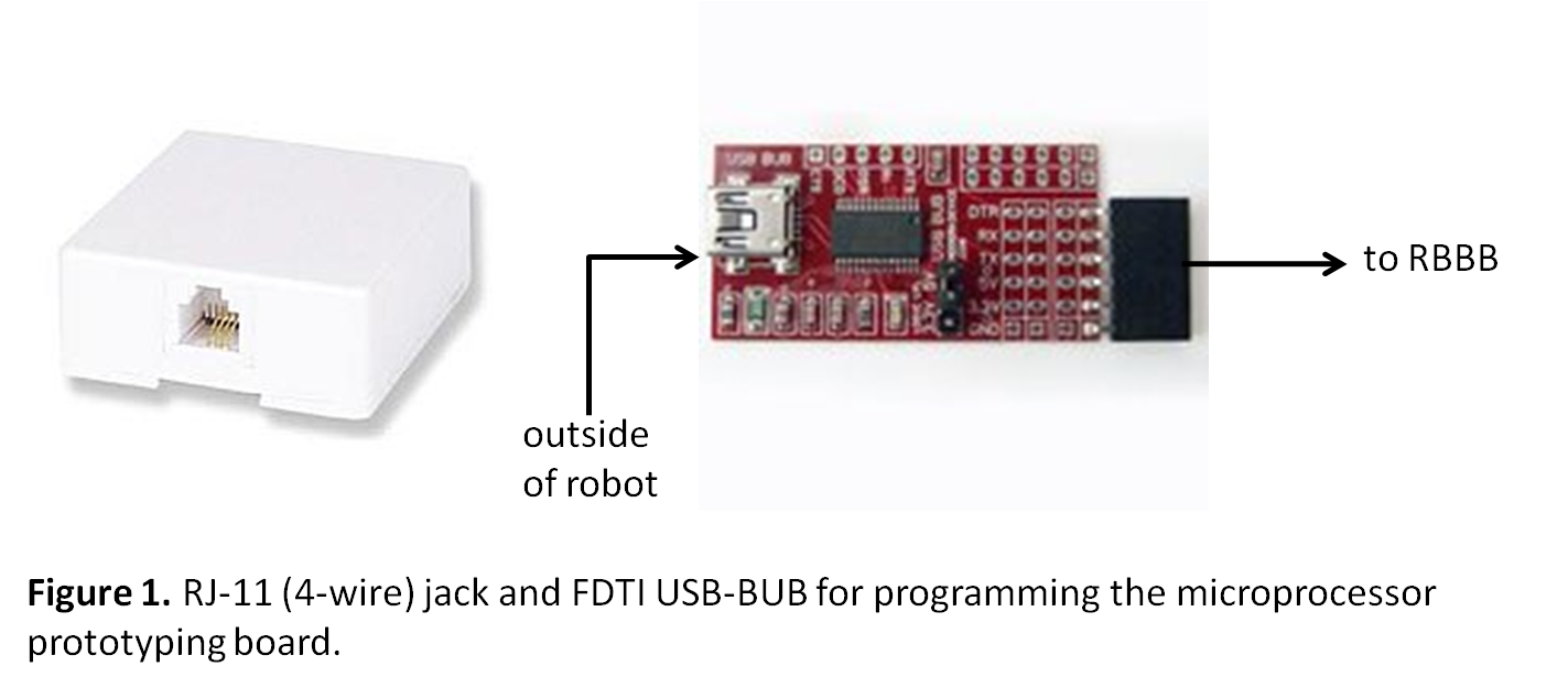
In the end, your robot will have two ports that will be visible (the RJ-11) jack and a mini-USB:
 Before the void setup()function, the software serial communication and servo objects need to be initialized:
// set up a new serial port
NewSoftSerial? mySerial(rxPin, txPin);
Servo myservo; // create servo object to control a servo
Also, any additional useful variables are declared:
int pos = 0; // variable to store the servo position
// for reset button
int val = 0; //stores state of input pin
Inside the setup function, all the used pins are set as output or input pins. For example, all code will include:
// define pin modes for tx, rx:
pinMode(rxPin, INPUT);
pinMode(txPin, OUTPUT);
Another important part of the setup() function
Also, the most important communication initialization is done here. Between all p.bots, use a 9600 baud rate connection. Your debugging baud rate can be set as you choose, but make sure the Serial Monitor is connected with the same baud rate.
// initialize serial communication:
mySerial.begin(9600); //NewSoftSerial
Serial.begin(9600); //To Serial Monitor.
The main loop starts by seeing if the reset button is pressed, if so it sends a character which is not a, b, c, or d. This way, the default conditions are applied.
// If reset pin pressed, send the robot to its default position.
val = digitalRead(reset);
if (val == HIGH) {
mySerial.print(char('e')); //set state to default.
Serial.print('Default state.'); //for debugging in Serial Monitor.
Serial.println();
}
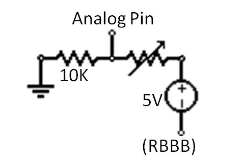
Next, activation of each sensor is checked. See the full code for all examples. The flex sensor is checked, then the "excited" character is sent based on a condition:
if (analogRead(bobHead)/4 < 50){
//neck nodded, excited
mySerial.print('c');
}
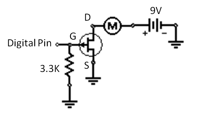
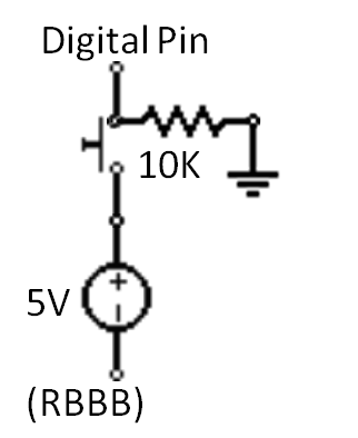
Determining the best output to work with for analog sensors may take some playing around with. The value is divided by four in this case, so that the output is an integer between 0 and 255. The condition "< 50" was based on the outputs with the given pull-down resistor (10K).
Finally, we wait to receive characters, and act accordingly. The if mySerial.available() function tells us whether or not we have established communication and characters are being sent.
// Received states. Do something in response.
if (mySerial.available()) {
Each possible p.bot output is controlled in the switch statement.
switch((char)mySerial.read()){
case 'a':
Serial.println("I'm so happy."); // To see on Serial Monitor.
digitalWrite(HEART, HIGH);
myservo.write(0);
break;
case 'b':
Serial.println("I'm so sad."); // To see on Serial Monitor.
// wave arm up and down - goodbye! ;(
myservo.attach(waveArm);
for(pos = 0; pos < 180; pos += 1) // goes from 0 degrees to 180 degrees
{ // in steps of 1 degree
myservo.write(pos); // tell servo to go to position in variable 'pos'
delay(15); // waits 15ms for the servo to reach the position
}
for(pos = 180; pos>=1; pos-=1) // goes from 180 degrees to 0 degrees
{
myservo.write(pos); // tell servo to go to position in variable 'pos'
delay(15); // waits 15ms for the servo to reach the position
}
myservo.detach();
break;
...
The default states are contained at the end of the switch statement.
default:
// turns everything off or back to normal.
digitalWrite(HEART, LOW);
digitalWrite(EYES, LOW);
digitalWrite(bodyTwist, LOW);
Serial.println("Normal.");
}
}
Mirror Code (MirrorPBot? )
This board also has a reset switch connected to it. However, there are no additional sensors or actuators. This board simply reads what the example p.bot sends and sends the same message back to it.
First, the communication and pinmode setup is similar to the example p.bot:
#include <NewSoftSerial.h>
#define BUTTON 2 // connect default push-button to digital pin 2
#define rxPin 3 // everyone uses the same software serial pins
#define txPin 4
// set up a new serial port
NewSoftSerial? mySerial(rxPin, txPin);
int val = 0; // stores state of input pin
void setup()
{
pinMode(BUTTON, INPUT); // digital sensor is an input
// define pin modes for tx, rx:
pinMode(rxPin, INPUT);
pinMode(txPin, OUTPUT);
// start serial port at 9600 bps:
mySerial.begin(9600); // baud rate for software serial connection
Serial.begin(9600); // to Serial Monitor (for debugging)
}
Again, if the reset button is pressed, send the p.bot to its default state.
void loop()
{
val = digitalRead(BUTTON);
//check if the default button was pressed
if (val == HIGH) {
mySerial.print(char('e')); //set state to default
Serial.print('Default state.'); //for debugging
Serial.println();
}
Check if the soft serial communication is established. Then, read the incoming character and send the same character back.
// Receive states, and send them back.
if (mySerial.available()) {
char inByte = (char)mySerial.read();
Serial.println(inByte); // for debugging
mySerial.print(inByte);
}
}
Final Deliverable
You are expected to deliver (in your corporate teams) a p.bot that:
1.) Communicates with another p.bot in the protocol described (9600 baud rate, implementing software serial on pins 3 and 4, sending characters "a, b, c, d" and a default condition).
2.) Responds to four different states (happy, sad, angry, excited.)
3.) It is assumed that you will use the provided RBBB kit and RJ-11 4 wire connections. See the Parts List for other suggested components (which can be found in nearby vendors).
Before the void setup()function, the software serial communication and servo objects need to be initialized:
// set up a new serial port
NewSoftSerial? mySerial(rxPin, txPin);
Servo myservo; // create servo object to control a servo
Also, any additional useful variables are declared:
int pos = 0; // variable to store the servo position
// for reset button
int val = 0; //stores state of input pin
Inside the setup function, all the used pins are set as output or input pins. For example, all code will include:
// define pin modes for tx, rx:
pinMode(rxPin, INPUT);
pinMode(txPin, OUTPUT);
Another important part of the setup() function
Also, the most important communication initialization is done here. Between all p.bots, use a 9600 baud rate connection. Your debugging baud rate can be set as you choose, but make sure the Serial Monitor is connected with the same baud rate.
// initialize serial communication:
mySerial.begin(9600); //NewSoftSerial
Serial.begin(9600); //To Serial Monitor.
The main loop starts by seeing if the reset button is pressed, if so it sends a character which is not a, b, c, or d. This way, the default conditions are applied.
// If reset pin pressed, send the robot to its default position.
val = digitalRead(reset);
if (val == HIGH) {
mySerial.print(char('e')); //set state to default.
Serial.print('Default state.'); //for debugging in Serial Monitor.
Serial.println();
}
Next, activation of each sensor is checked. See the full code for all examples. The flex sensor is checked, then the "excited" character is sent based on a condition:
if (analogRead(bobHead)/4 < 50){
//neck nodded, excited
mySerial.print('c');
}
Determining the best output to work with for analog sensors may take some playing around with. The value is divided by four in this case, so that the output is an integer between 0 and 255. The condition "< 50" was based on the outputs with the given pull-down resistor (10K).
Finally, we wait to receive characters, and act accordingly. The if mySerial.available() function tells us whether or not we have established communication and characters are being sent.
// Received states. Do something in response.
if (mySerial.available()) {
Each possible p.bot output is controlled in the switch statement.
switch((char)mySerial.read()){
case 'a':
Serial.println("I'm so happy."); // To see on Serial Monitor.
digitalWrite(HEART, HIGH);
myservo.write(0);
break;
case 'b':
Serial.println("I'm so sad."); // To see on Serial Monitor.
// wave arm up and down - goodbye! ;(
myservo.attach(waveArm);
for(pos = 0; pos < 180; pos += 1) // goes from 0 degrees to 180 degrees
{ // in steps of 1 degree
myservo.write(pos); // tell servo to go to position in variable 'pos'
delay(15); // waits 15ms for the servo to reach the position
}
for(pos = 180; pos>=1; pos-=1) // goes from 180 degrees to 0 degrees
{
myservo.write(pos); // tell servo to go to position in variable 'pos'
delay(15); // waits 15ms for the servo to reach the position
}
myservo.detach();
break;
...
The default states are contained at the end of the switch statement.
default:
// turns everything off or back to normal.
digitalWrite(HEART, LOW);
digitalWrite(EYES, LOW);
digitalWrite(bodyTwist, LOW);
Serial.println("Normal.");
}
}
Mirror Code (MirrorPBot? )
This board also has a reset switch connected to it. However, there are no additional sensors or actuators. This board simply reads what the example p.bot sends and sends the same message back to it.
First, the communication and pinmode setup is similar to the example p.bot:
#include <NewSoftSerial.h>
#define BUTTON 2 // connect default push-button to digital pin 2
#define rxPin 3 // everyone uses the same software serial pins
#define txPin 4
// set up a new serial port
NewSoftSerial? mySerial(rxPin, txPin);
int val = 0; // stores state of input pin
void setup()
{
pinMode(BUTTON, INPUT); // digital sensor is an input
// define pin modes for tx, rx:
pinMode(rxPin, INPUT);
pinMode(txPin, OUTPUT);
// start serial port at 9600 bps:
mySerial.begin(9600); // baud rate for software serial connection
Serial.begin(9600); // to Serial Monitor (for debugging)
}
Again, if the reset button is pressed, send the p.bot to its default state.
void loop()
{
val = digitalRead(BUTTON);
//check if the default button was pressed
if (val == HIGH) {
mySerial.print(char('e')); //set state to default
Serial.print('Default state.'); //for debugging
Serial.println();
}
Check if the soft serial communication is established. Then, read the incoming character and send the same character back.
// Receive states, and send them back.
if (mySerial.available()) {
char inByte = (char)mySerial.read();
Serial.println(inByte); // for debugging
mySerial.print(inByte);
}
}
Final Deliverable
You are expected to deliver (in your corporate teams) a p.bot that:
1.) Communicates with another p.bot in the protocol described (9600 baud rate, implementing software serial on pins 3 and 4, sending characters "a, b, c, d" and a default condition).
2.) Responds to four different states (happy, sad, angry, excited.)
3.) It is assumed that you will use the provided RBBB kit and RJ-11 4 wire connections. See the Parts List for other suggested components (which can be found in nearby vendors).
- figure1_pbotconnections.png:
- figure2_connection.png:
- switchcircuit.png:
- LEDcircuit.png:

- forcesensorcircuit.png:
Before the void setup()function, the software serial communication and servo objects need to be initialized:
// set up a new serial port
NewSoftSerial? mySerial(rxPin, txPin);
Servo myservo; // create servo object to control a servo
Also, any additional useful variables are declared:
int pos = 0; // variable to store the servo position
// for reset button
int val = 0; //stores state of input pin
Inside the setup function, all the used pins are set as output or input pins. For example, all code will include:
// define pin modes for tx, rx:
pinMode(rxPin, INPUT);
pinMode(txPin, OUTPUT);
Another important part of the setup() function
Also, the most important communication initialization is done here. Between all p.bots, use a 9600 baud rate connection. Your debugging baud rate can be set as you choose, but make sure the Serial Monitor is connected with the same baud rate.
// initialize serial communication:
mySerial.begin(9600); //NewSoftSerial
Serial.begin(9600); //To Serial Monitor.
The main loop starts by seeing if the reset button is pressed, if so it sends a character which is not a, b, c, or d. This way, the default conditions are applied.
// If reset pin pressed, send the robot to its default position.
val = digitalRead(reset);
if (val == HIGH) {
mySerial.print(char('e')); //set state to default.
Serial.print('Default state.'); //for debugging in Serial Monitor.
Serial.println();
}
Next, activation of each sensor is checked. See the full code for all examples. The flex sensor is checked, then the "excited" character is sent based on a condition:
if (analogRead(bobHead)/4 < 50){
//neck nodded, excited
mySerial.print('c');
}
Determining the best output to work with for analog sensors may take some playing around with. The value is divided by four in this case, so that the output is an integer between 0 and 255. The condition "< 50" was based on the outputs with the given pull-down resistor (10K).
Finally, we wait to receive characters, and act accordingly. The if mySerial.available() function tells us whether or not we have established communication and characters are being sent.
// Received states. Do something in response.
if (mySerial.available()) {
Each possible p.bot output is controlled in the switch statement.
switch((char)mySerial.read()){
case 'a':
Serial.println("I'm so happy."); // To see on Serial Monitor.
digitalWrite(HEART, HIGH);
myservo.write(0);
break;
case 'b':
Serial.println("I'm so sad."); // To see on Serial Monitor.
// wave arm up and down - goodbye! ;(
myservo.attach(waveArm);
for(pos = 0; pos < 180; pos += 1) // goes from 0 degrees to 180 degrees
{ // in steps of 1 degree
myservo.write(pos); // tell servo to go to position in variable 'pos'
delay(15); // waits 15ms for the servo to reach the position
}
for(pos = 180; pos>=1; pos-=1) // goes from 180 degrees to 0 degrees
{
myservo.write(pos); // tell servo to go to position in variable 'pos'
delay(15); // waits 15ms for the servo to reach the position
}
myservo.detach();
break;
...
The default states are contained at the end of the switch statement.
default:
// turns everything off or back to normal.
digitalWrite(HEART, LOW);
digitalWrite(EYES, LOW);
digitalWrite(bodyTwist, LOW);
Serial.println("Normal.");
}
}
Mirror Code (MirrorPBot? )
This board also has a reset switch connected to it. However, there are no additional sensors or actuators. This board simply reads what the example p.bot sends and sends the same message back to it.
First, the communication and pinmode setup is similar to the example p.bot:
#include <NewSoftSerial.h>
#define BUTTON 2 // connect default push-button to digital pin 2
#define rxPin 3 // everyone uses the same software serial pins
#define txPin 4
// set up a new serial port
NewSoftSerial? mySerial(rxPin, txPin);
int val = 0; // stores state of input pin
void setup()
{
pinMode(BUTTON, INPUT); // digital sensor is an input
// define pin modes for tx, rx:
pinMode(rxPin, INPUT);
pinMode(txPin, OUTPUT);
// start serial port at 9600 bps:
mySerial.begin(9600); // baud rate for software serial connection
Serial.begin(9600); // to Serial Monitor (for debugging)
}
Again, if the reset button is pressed, send the p.bot to its default state.
void loop()
{
val = digitalRead(BUTTON);
//check if the default button was pressed
if (val == HIGH) {
mySerial.print(char('e')); //set state to default
Serial.print('Default state.'); //for debugging
Serial.println();
}
Check if the soft serial communication is established. Then, read the incoming character and send the same character back.
// Receive states, and send them back.
if (mySerial.available()) {
char inByte = (char)mySerial.read();
Serial.println(inByte); // for debugging
mySerial.print(inByte);
}
}
Final Deliverable
You are expected to deliver (in your corporate teams) a p.bot that:
1.) Communicates with another p.bot in the protocol described (9600 baud rate, implementing software serial on pins 3 and 4, sending characters "a, b, c, d" and a default condition).
2.) Responds to four different states (happy, sad, angry, excited.)
3.) It is assumed that you will use the provided RBBB kit and RJ-11 4 wire connections. See the Parts List for other suggested components (which can be found in nearby vendors).
Ideas, requests, problems regarding TWiki? Send feedback