Category: SummerBlogs
Documentation
General Lab
Cardiac Simulator
- Olivia's Final SURI Poster | Origami Heart: Benchtop Simulation of Left-Ventricular Motion
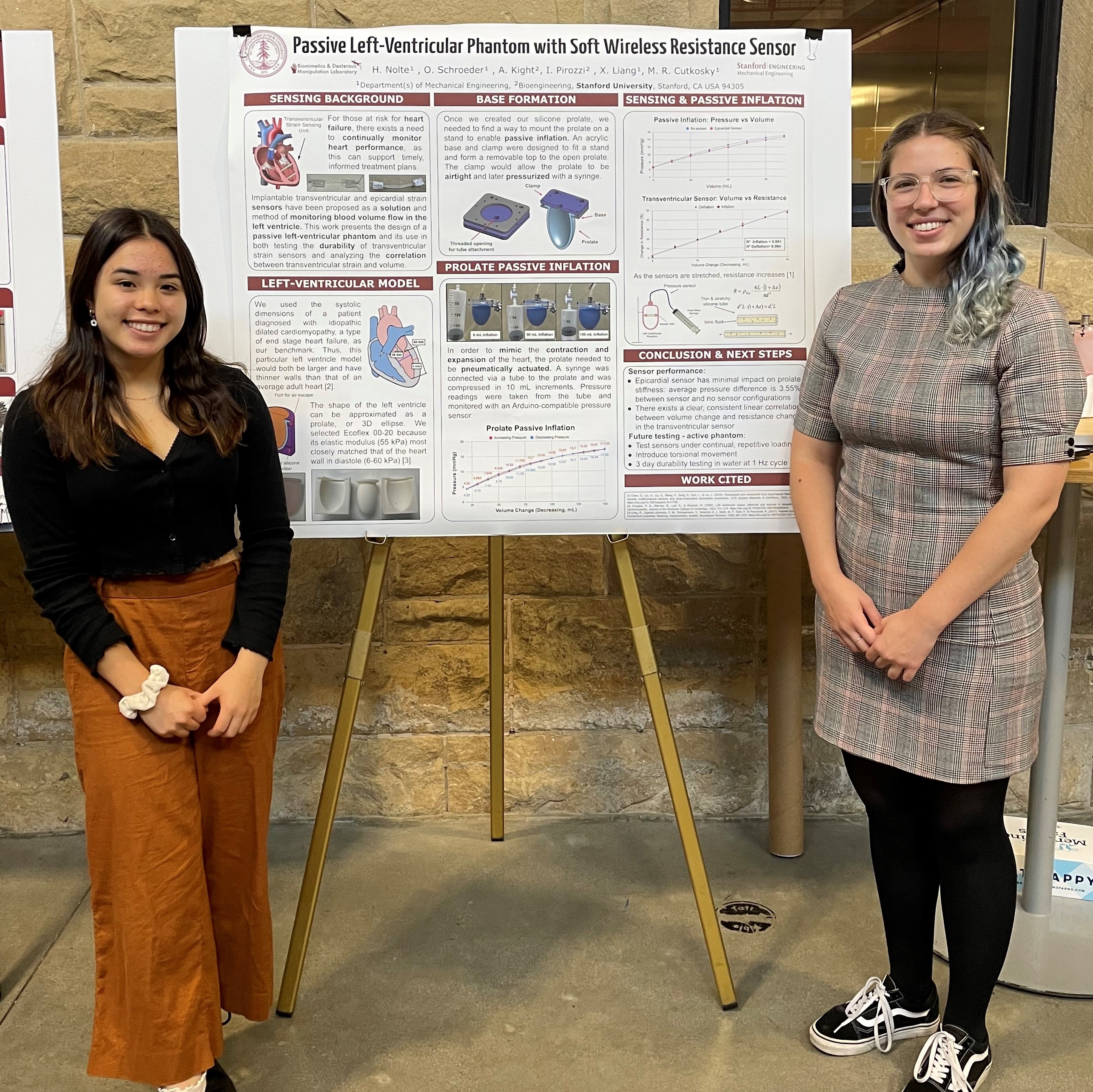
- Heather's Final SURI Poster | Passive Left-Ventricular Phantom with Soft Wireless Resistance Sensor
- SURI Meeting Presentation Slides (If some of the writing overlaps, refresh the page to fix the issue.)
- Cardiac simulator notes
- Kresling fabrication guide
- Lit review
Week 10
Friday, August 26th
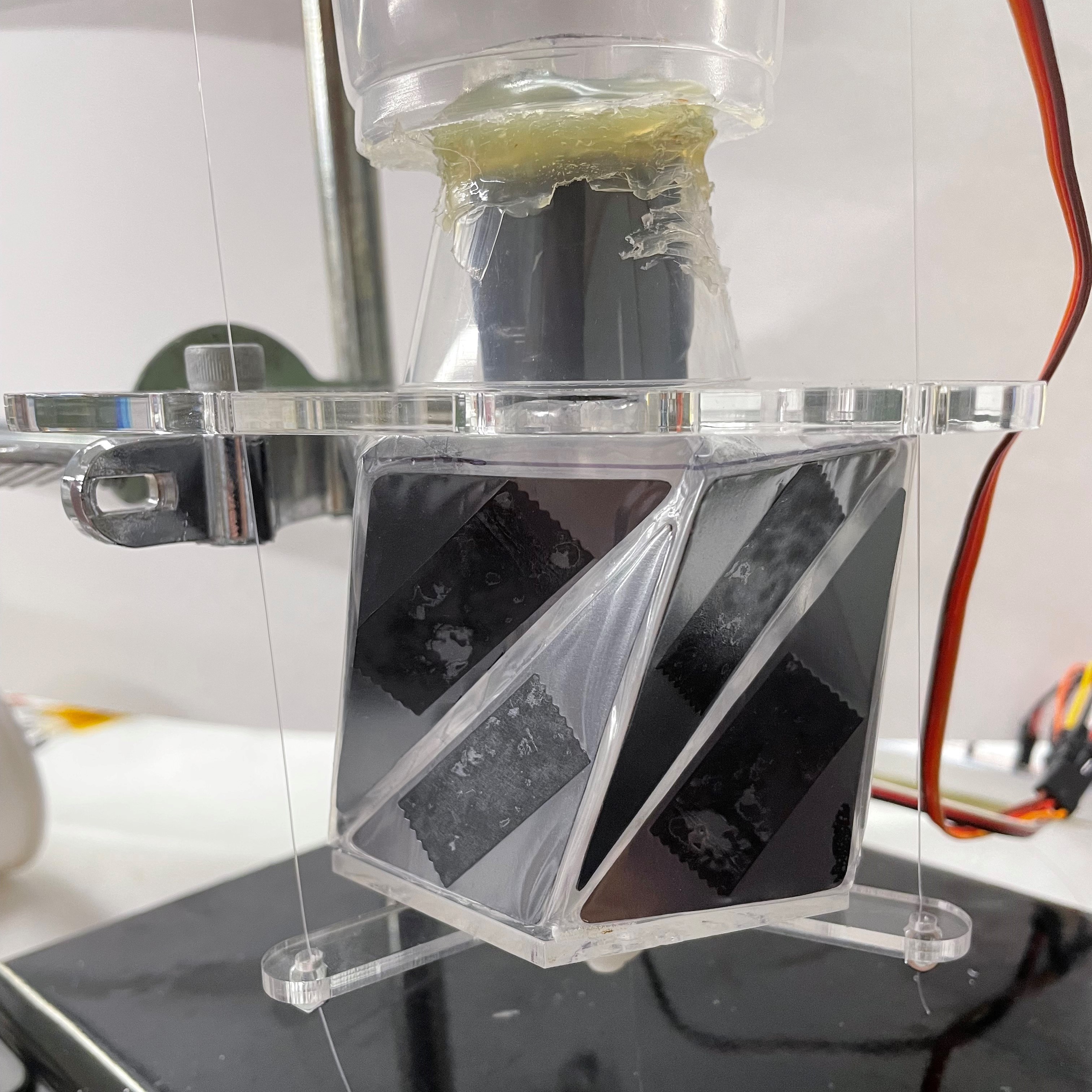
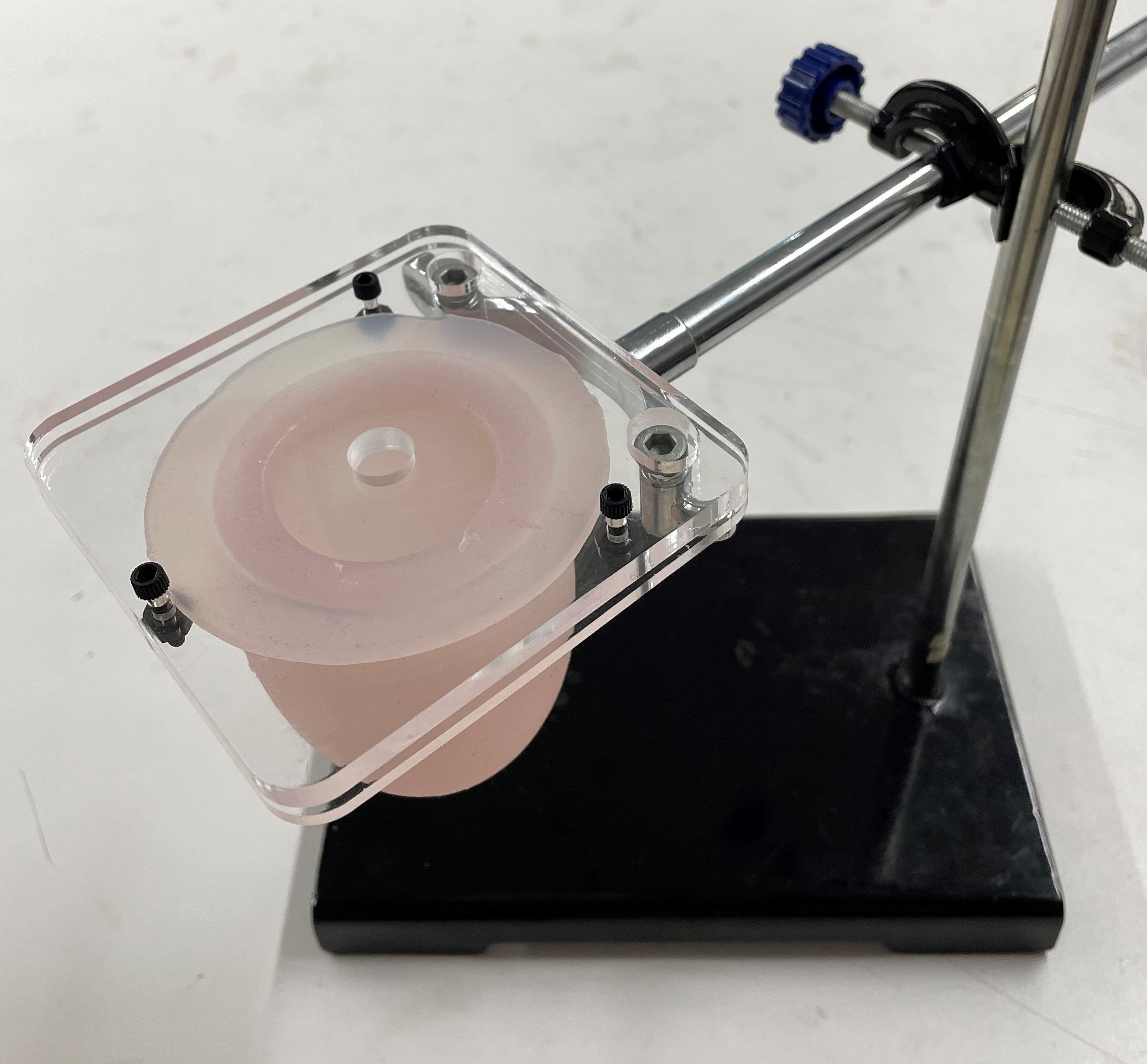
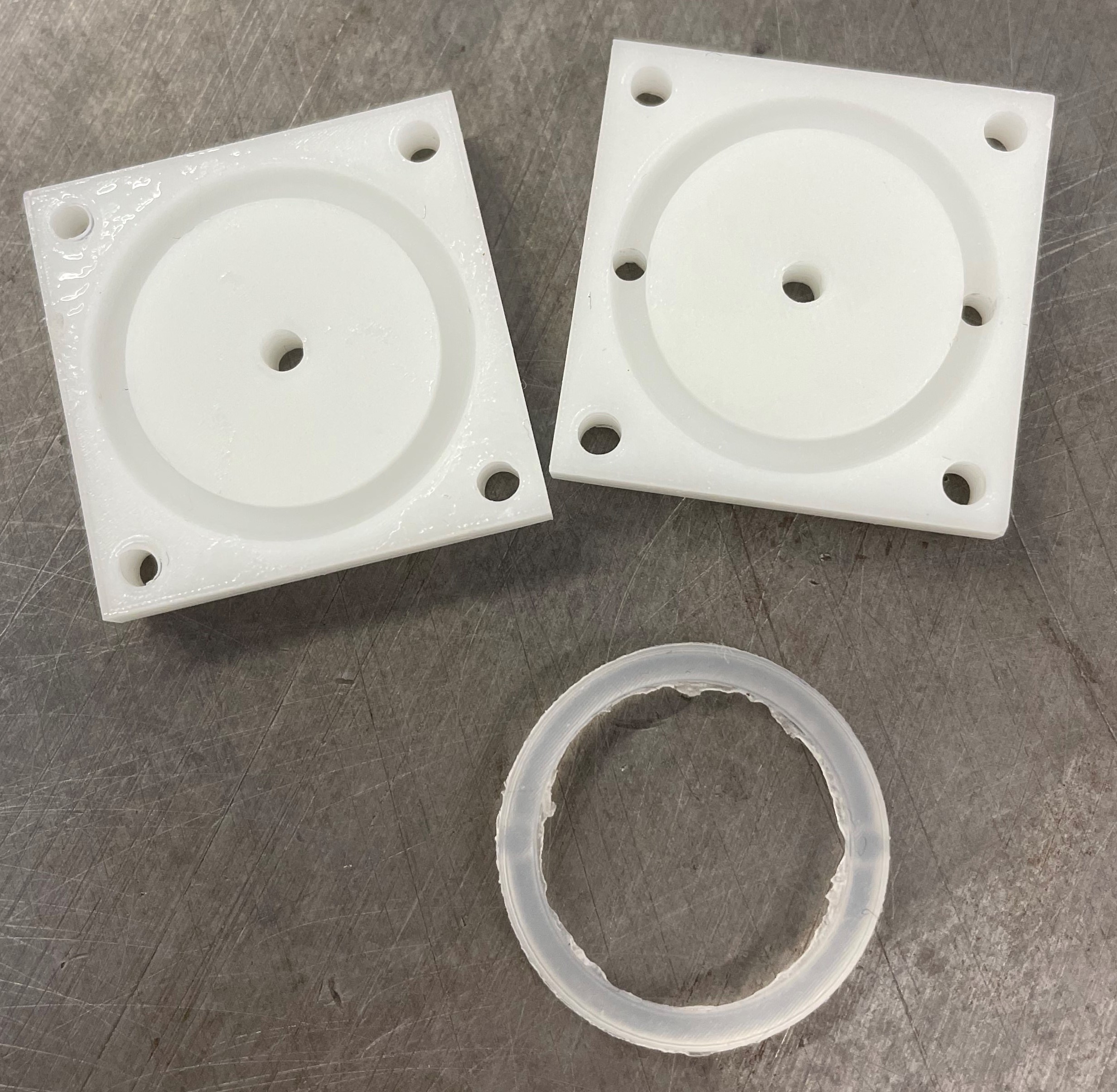
I came in early this morning to finish making the new reservoir for the Kresling setup. I reheated the 3D printed plate to fix some warping that had occurred during curing. Then, I glued on a clear plastic cup as the reservoir.
After lunch, we had our final SURI poster session. I got a lot of questions and some people were really interested in the work we've done. There were a few people who asked me how the device would be implanted into the heart, so I had to clarify that the sensor, not the Kresling device, would be implanted. It was helpful to be next to Heather's poster as we were able to reference each other's posters to give more information when asked. Ali insisted on having her Mendocino Farms box in the picture.
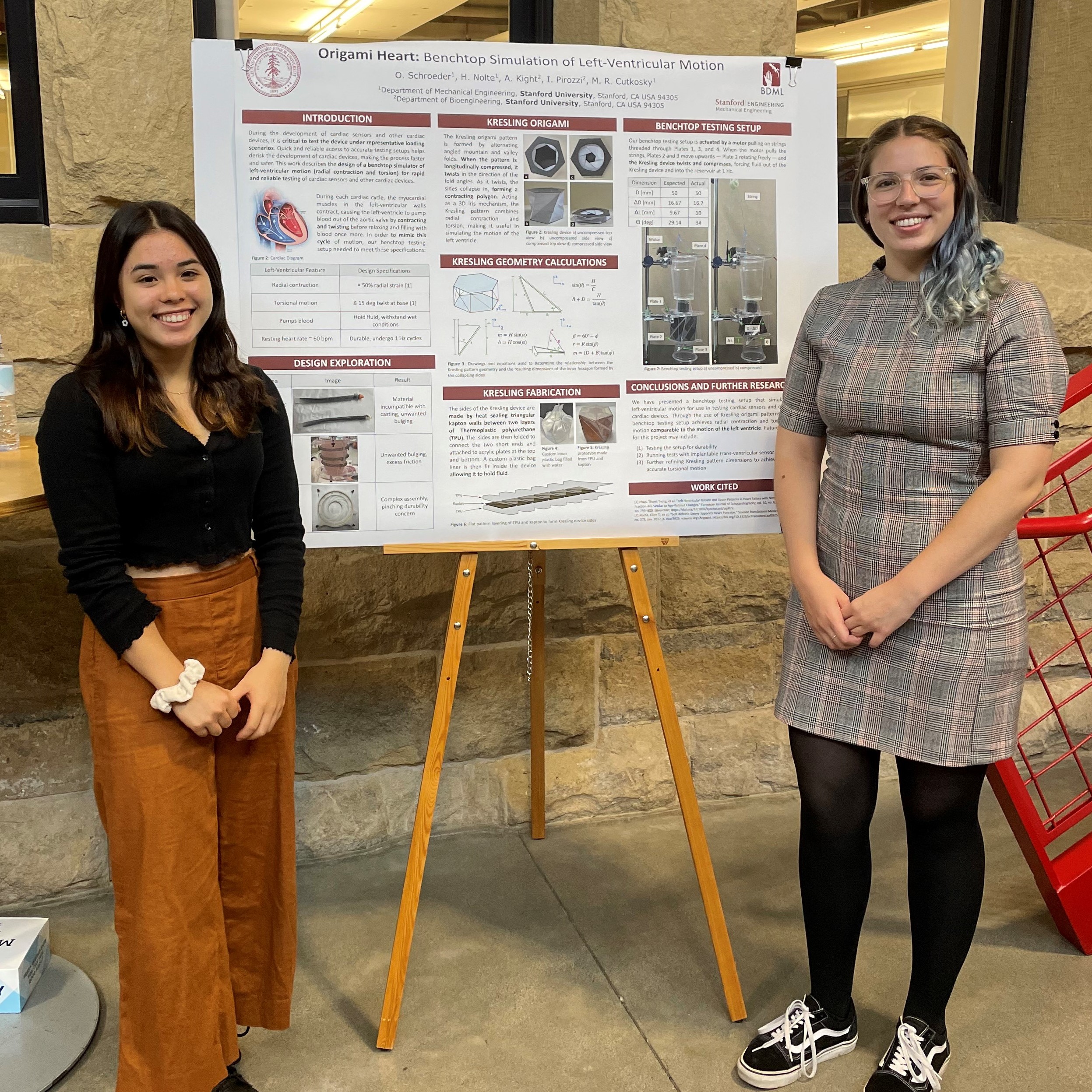
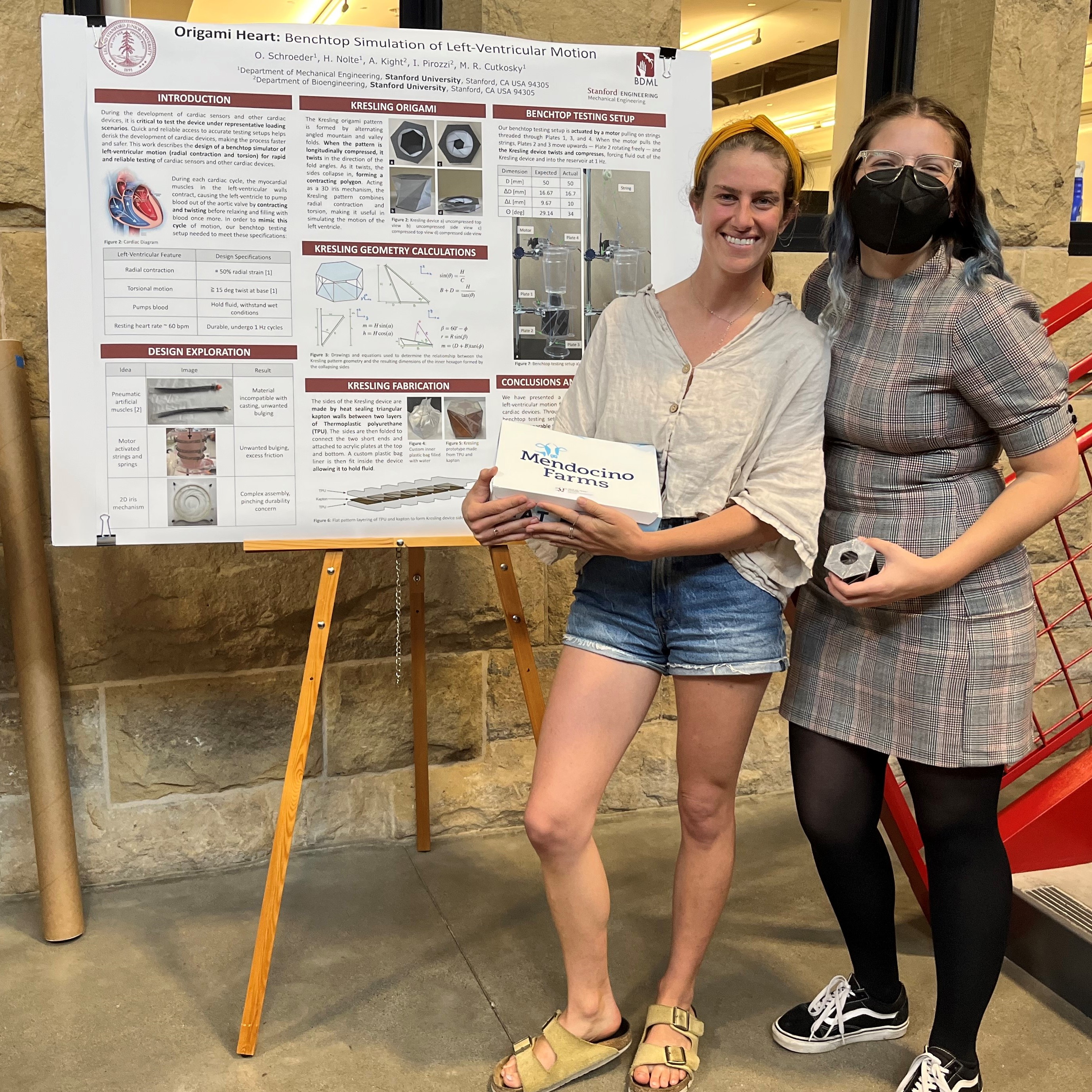
SURI Final Poster Presentation
I had a really wonderful time working at the BDML this summer and will miss everyone. I plan to come visit every once in a while and bring in whatever I've baked that week.
Thursday, August 25th
In the morning, I finished the reservoir CAD. We decided to just 3D print the plate that will clamp down on the O-ring to seal the connection and glue on a clear cup as the reservoir. This will allow us to see how much water is ejected in each cycle of the Kresling device.
I then spent my time making sure everything was clearly documented to ensure a smooth handover of the project once Heather and I leave. I added some handover notes to the Cardiac Simulator Notes Google Doc and linked any other relevant documents.
Wednesday, August 24th
I spent the morning working on creating another hydrogel sensor. This time, we wanted to use thread to attach the plastic snap buttons and thread the electrode strings through the gel itself. The threaded sensor was able to withstand stretching without breaking. However, when tested, we found that the sensor's resistance reading was drifting upwards. Ali thinks it could be an issue with the readout circuitry.
Later, in our medical device meeting, Mark suggested using an O-ring to make the connection between the top plate of the Kresling device and the reservoir watertight. I looked into O-rings, selected one from McMaster to order, and started making a CAD model for the reservoir that we can 3D print on the Form printer.
Monday, August 22nd

Watertight Kresling Device
Today I finished making the Kresling device watertight by attaching the top plate to the Kresling using acrylic tape and sealing the edges with Sil-Poxy. Before running the device with water, we will need to decide on how to attach the reservoir such that it is watertight but allows us to insert and remove sensors for testing.
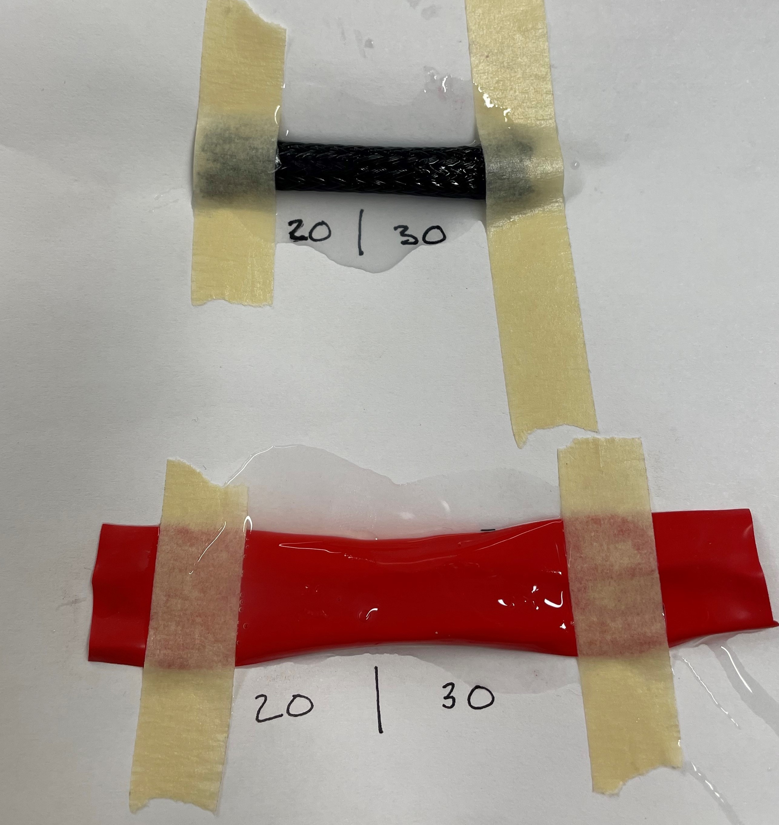
In the afternoon, Heather and I worked on testing a sensor in the volume constrained prolate setup. Ali and Ileana have found that the resistance readings from the sensors are lower when tested in water. Ali did some reading and found other articles stating similar findings. We've theorized that it may be due to hydrostatic pressure affecting the sensor. To test this, we want to insert a resistance sensor into the prolate setup and vary the pressure while keeping the volume (specifically the length of the sensor) constant. First, we are trying the tests with air and then will move on to filling the prolate with water.
Week 9
Friday, August 19th
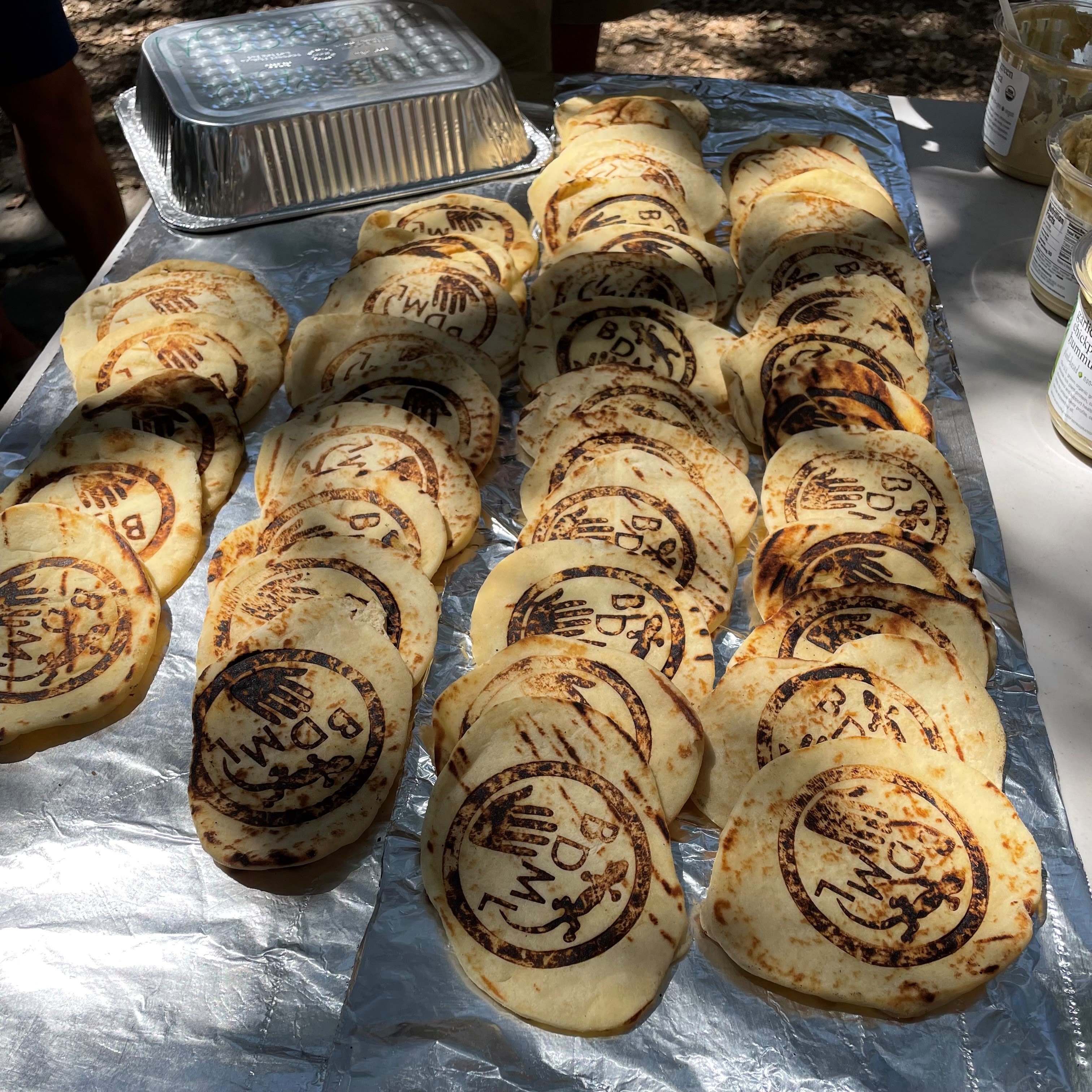
BDML Branded Naan at MERL BBQ
In the morning, I finalized and submitted my poster. Then, we worked on the BBQ. It was really fun and delicious!
In the afternoon, the epoxy finished curing on the bag, but just testing it once showed that the epoxy was already pealing away from the bag. This shows that the seal likely wouldn't last very long. We decided to work on making the Kresling device itself watertight so that we can fill it with water without using the bag insert. To do this, I sealed the hole in the bottom plate where it is fastened to the rotating plate using Sil-Poxy. I then sealed the outside edges along the base plate of the Kresling device with Sil-Poxy as well.
Just before leaving for the day, Ali and I attached a hydrogel sensor to the Kresling device and hooked it up to the readout circuitry. We were able to see how the resistance varied as the Kresling device "pumped."
Thursday, August 18th
I spent the morning creating a step-by-step guide on how to fabricate the Kresling device. I want to make sure that someone can make another if needed even after Heather and I leave the lab at the end of the summer. I added figured to try and make the process as clear as possible to understand. Heather started following the instructions to make a backup Kresling device and see if the instructions are followable. She will take pictures throughout the process so that we can add them to the document.
In the afternoon, we had a poster review session so everyone could give us feedback on our posters and we could get some practice presenting our work. I got some good feedback on how adjust my figures to better communicate the motion of the benchtop setup. Afterwards, we spent the rest of the afternoon making skewers for the BBQ tomorrow.
Wednesday, August 17th
Benchtop Setup at 0.5 Hz
Today, Heather and I spent the morning working on our posters from home before coming into lab to meet with Ali. This is the first research poster I've made, so I used previous posters made by Ali and Ileana or Tony as guides for formatting and writing style.
We also worked on increasing the speed of the benchtop setup from 0.5 Hz to 1 Hz and recalibrating the motion. After some time running, we noticed water leaking. I took our the bag and tested it for leaks, finding that water was leaking from where the bag connects to the tube at the top. We had this issue before and had used Sil-Poxy to seal the connection, but the Sil-Poxy was detaching from the bag over time. I trimmed off the Sil-Poxy and used an epoxy to reseal the connection.
Tuesday, August 16th
In the morning, Heather and I measured the actual contraction of the Kresling device. Our calculations showed that the inner diameter of the device should contract from 50mm to 33.3mm when longitudinally contracted from 52.5mm to 42mm. The actual measurements show that measuring the diameter across different sides of the hexagonal Kresling device produces different results. This is likely due to error in the fabrication of the device. While two of the measurements were slightly larger than we had predicted, one matched our calculations. We marked the device to ensure we attach the sensor to the side that matches the measurements we want when testing.
In the afternoon, we focused on continuing our work on our posters for the final SURI poster session.
Monday, August 15th
Heather and I gave our research presentation at the SURI meeting today. The session was unfortunately rushed, so there wasn't time for more than one question at the end. Besides the meeting, Heather and I worked on getting the new servo motors installed in the setup and making adjustments to get the right motion. We plan to meet with Ali and Ileana tomorrow morning to discuss what we should focus our time on in our last two weeks. The rest of our time today we spent working on our final posters.
Week 8
Friday, August 12th
Kresling Device in Stand
Today I started working on my final research poster while heather worked on getting the servo motor attached to the stand. Once the motors were moving, we worked on tuning the setup to the correct range of motion we want. The, we added water to the inserted bag to see if the motor could maintain the desired motion with the added weight. The motor was struggling to lift the water and would slip when we stopped it, causing the motion to decrease. To fix this, we are ordering stronger motors and plan to attach them on Monday.
Thursday, August 11th
Kresling Device Fabrication
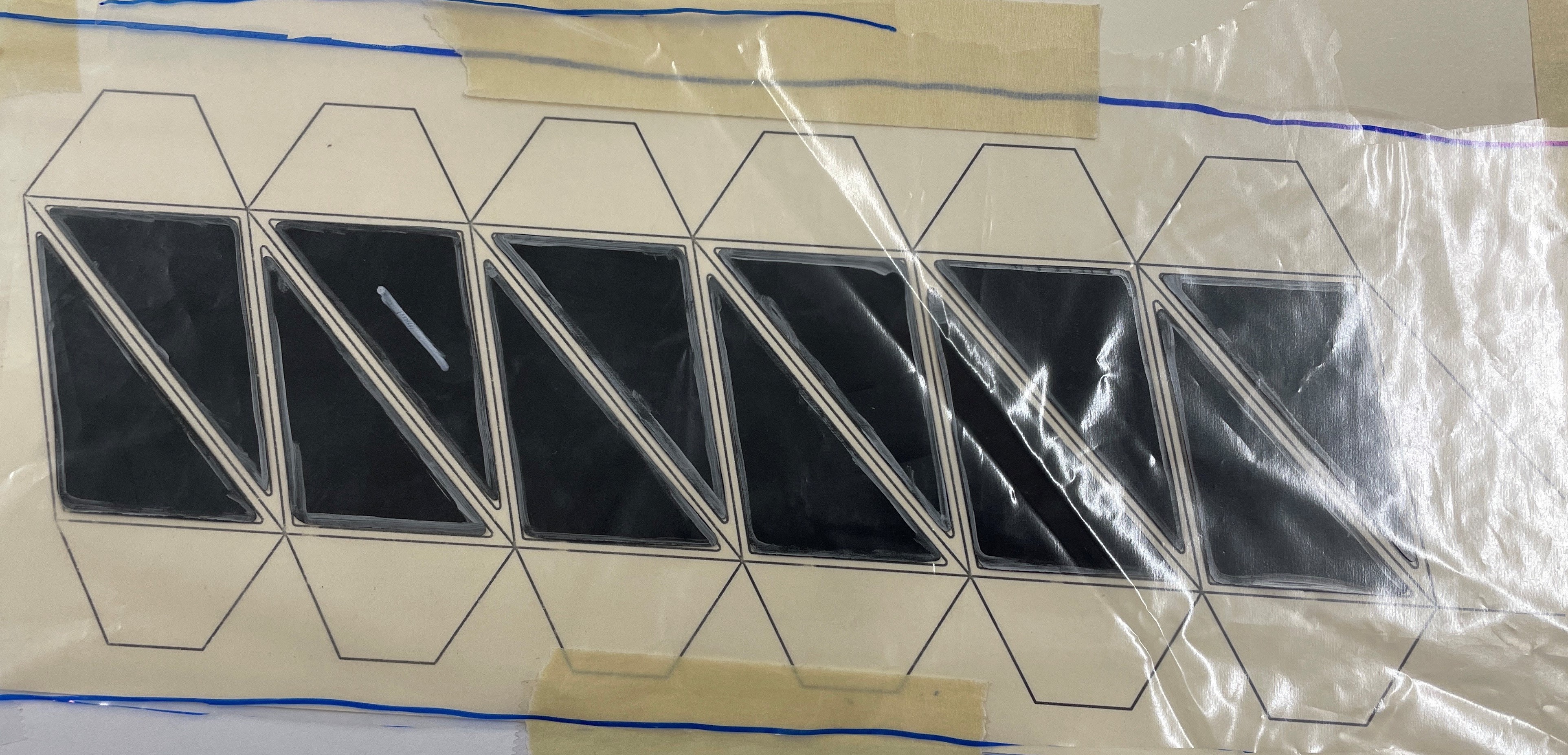
Today Heather and I worked on our slides for our presentation at the SURI meeting Monday. I also worked on fabricating a new TPU and kapton Kresling device. This time, instead of using the impulse sealer to heat seal the TPU layers together between the kapton walls, I used the T-shirt press. The TPU to sealed to itself in the T-shirt press, but some residue on the paper caused it to stick to the TPU. I was able to get most of it off. I then attached the Kresling pattern to the acrylic base by super gluing the TPU tabs down to the acrylic.
At the end of the day, Heather and I discussed how we plan to split up our work to create two distinct posters for the SURI final poster presentation. We plan to create one poster covering the passive phantom and it's use in sensor testing and the other poster covering the creation of a simulator of left-ventricular motion.
Tuesday, August 9th
With the equations I found yesterday, I created a spreadsheet to track how changing each constant would change the resulting motion. Using this, I was able to find the required geometries to achieve 50% radial strain with a torsion over 7 degrees and a change in height achievable by our actuation setup.
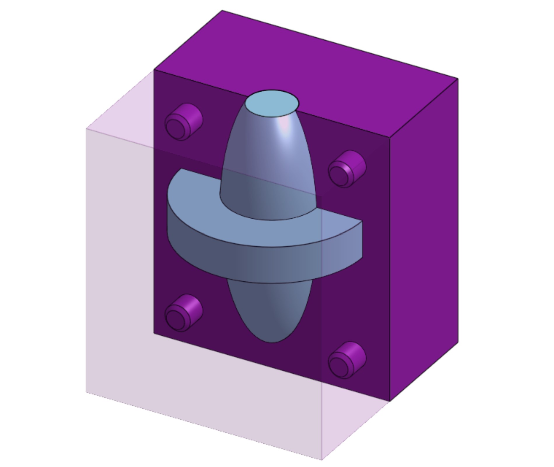
After deciding on the dimensions, Heather and I applied them to design the acrylic plates that form the top and bottom of the Kresling device and the actuation setup. In order to apply force upwards to collapse the Kresling device while allowing free rotation about the center axis, we are using two thrust bearings sandwiched between the base plate and the actuation plate.
Monday, August 8th
Today's focus was figuring out the dimensions we needed to make the triangles that make up the Kresling pattern to allow the motion we want. I needed to figure out equations to relate the dimensions in each orientation as the Kresling device moved in 3D space. In order to do this, I broke the motion down to 2D triangles as they appeared in the top, front, and right planes. I was able to derive an equation relating the height of the fixed side triangle dimensions, the varying height of the Kresling device, and the angle and diameter of the inner hexagon formed by the collapsing walls.
Week 7
Thursday, August 4th

TPU and Kapton Kresling
TPU Kresling Device Test
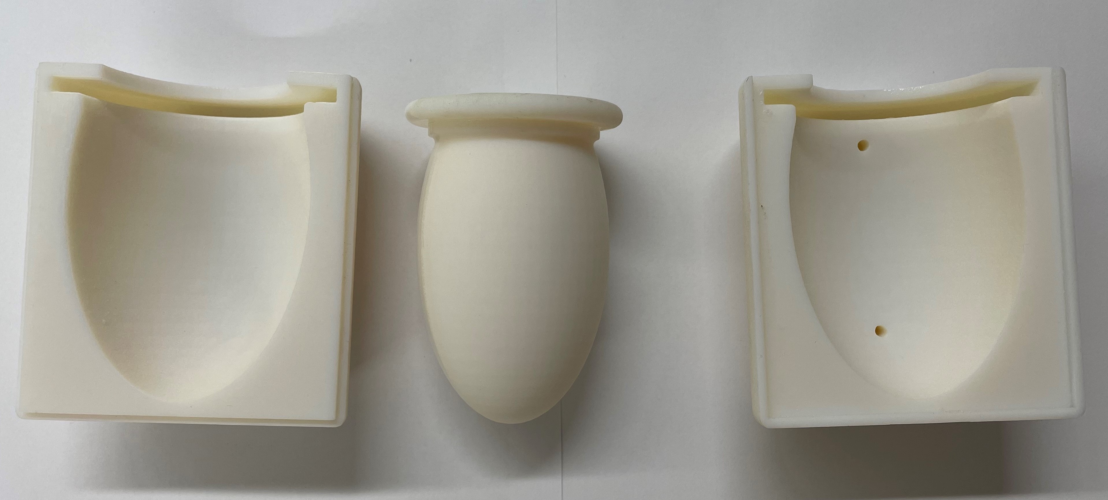
Ileana had the idea to use thermoplastic polyurethane heat sealed around kapton pieces to form the Kresling pattern. The TPU is flexible which makes it forgiving to slight errors in angles caused by human error in fabrication. It can also be heat sealed. This allowed me to cut out two layers of TPU, place cut out kapton walls (slightly undersized to allow gaps for the hinges) between the TPU layers, and heat seal them together in between the walls using the impulse sealer. The result was a Kresling prototype that was very smooth in actuation and wouldn't break if gotten wet. I inserted the bag assembly, and Ileana helped me test the prototype with water. We found that filling the prototype with water all the way caused the walls to bulge out, but if we filled it only part way, we were easily able to actuate the motion by pushing up on the bottom of the prototype.
Wednesday, August 3rd
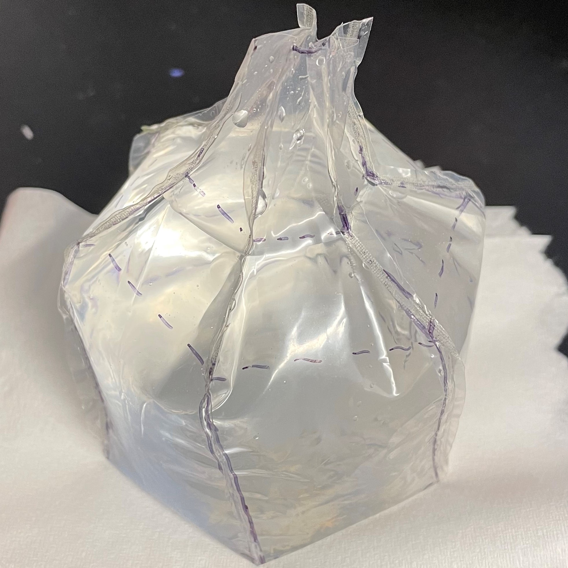
Kresling Device Bag
Kresling Device Test
Today I tried a new fabrication technique for the Kresling pattern. To increase the stiffness of the walls while allowing for easy bending at the creases, I glued on kapton walls to an existing printer paper Kresling prototype. This new prototype was able to be collapsed repeatedly without crinkling the paper and causing the form to warp over time. later, I created a bag to insert into the Kresling prototype. I wanted the bag to be the shape of the inside of the prototype in the open state. In order to achieve this, I printed a flat pattern template and traced it onto a sheet of plastic I salvaged from a spare plastic bag. I then used the impulse sealer to seal the bag along each line, forming a hexagonal prism with a opening at the top to attach to a tube. Once the bag was created, I attached it to a tube and cup and inserted it into the Kresling prototype. I then tested the prototype. The water was able to open the collapsed prototype, but the water was too heavy and the prototype too flimsy to allow for me to push the prototype closed and eject the water. The prototype had gotten wet in the process of testing and quickly tore at the seams when tested again. The next step is to replace the paper to make the Kresling pattern resilient to moisture.
Tuesday, August 2nd
Today I worked on more Kresling prototypes and figuring out the motion of Kresling patterns with varying geometries. I created a sketch in Onshape to visualize the top view of the Kresling pattern so as to see the changing inner diameter. I varied the number of sides to see how the relationship between torsion and radial strain changed. I found that the more sides the base polygon had, the more torsion was required to achieve the corresponding 50% strain we want. Later in the afternoon, Ali, Ileana, Heather, and I met with Crystal to discuss fabrication techniques. She is working on origami robotics in her project, so she was able to share that knowledge with us. she recommended trying a layering technique where stiff walls were attached to a flexible layer to allow bending at manufactured "hinges."
Week 6
Friday, July 29th
Cylindrical Kresling Pattern
Ali and Ileana had an idea for a new approach to combining torsion and contraction into one mechanism. It's called the Kresling origami pattern. Folds in the paper cause it to twist as it collapses. The inner form of the paper assembly contracts as this twisting occurs. Heather and I spent the day making simple cylindrical versions of the pattern, but we plan to try conical versions that could better match the shape of the left ventricle. The idea we have so far is to create a Kresling origami pattern and insert a plastic or silicone bag into the cavity. When we fill the bag with fluid it will expand to the inner shape and then contract again when the pattern is externally compressed in the longitudinal direction.
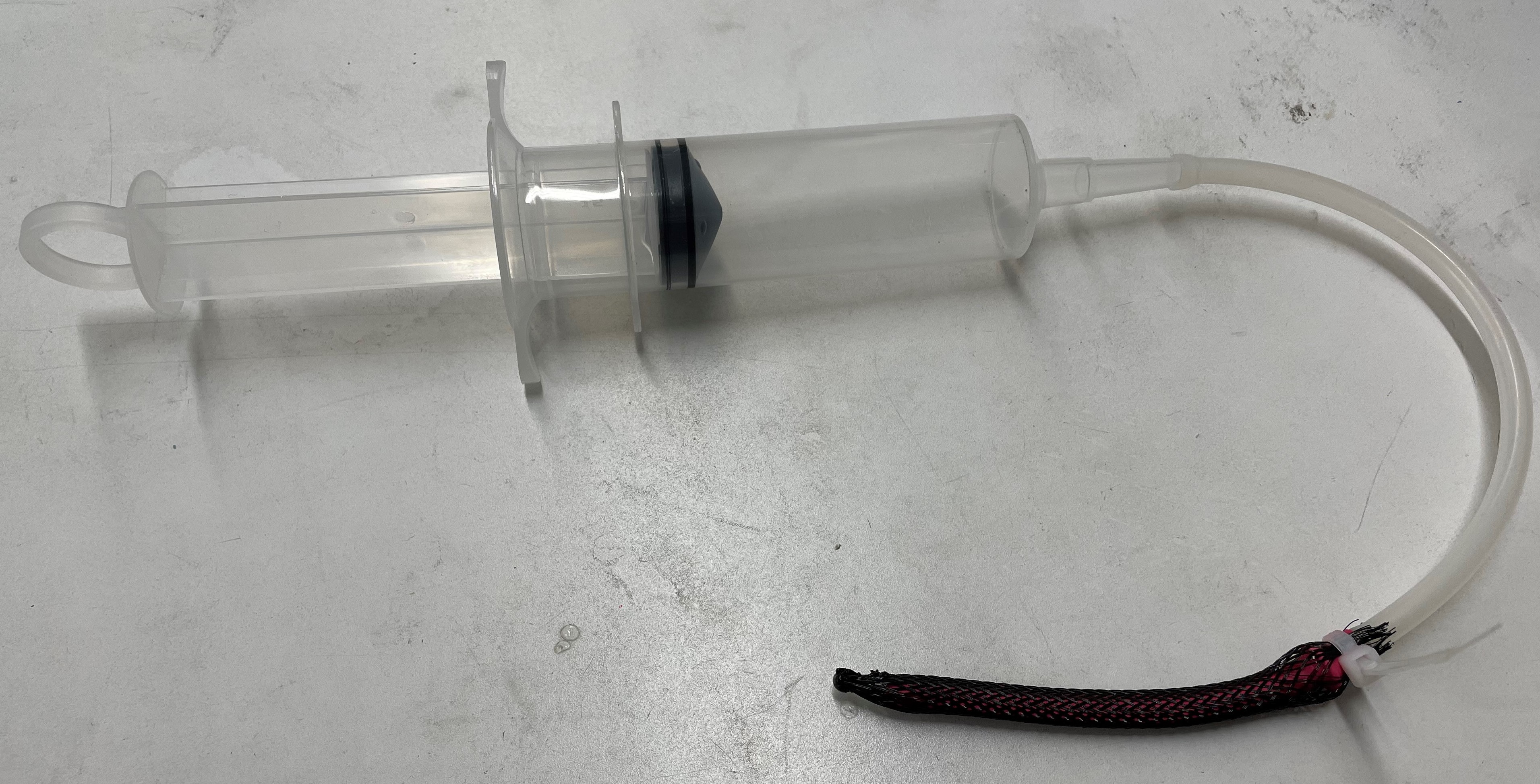
Later in the day I made a prototype of the bag filled Kresling pattern. I took an empty plastic bag and heat sealed it into a prism that roughly fit inside the contraption. I had the top of the bag come together and through a hole cut in the top plate of the contraption. I then wrapped the bag around a syringe and sealed it (not airtight, but good enough for this prototype) with a rubber band. This video shows me testing the inflatable Kresling prototype.
Thursday, July 28th
Today I assembled the 3D printed parts to make the iris mechanism. The leaves were warped from curing, so it was difficult to lay them flat on top of each other. I was able to get the mechanism fully assembled, but there was a lot of friction that made it hard to actuate. I disassembled the mechanism and applied a silicone lubricant to the joints before reassembling. The mechanism moved more smoothly, but easily moved out of place, dislodging the leaves and causing the mechanism to jam. I tried to prevent this by gluing on makeshift walls to the inside of the base and top rings to keep the rotator in line. This helped quite a bit, but the walls were will not strong enough to keep the rotator from moving out or alignment during actuation. While the iris mechanism show some potential, it is a complex assembly that would need a lot of work to make useable in this application.
Tuesday, July 26th
Iris Mechanism CAD
Today I worked on creating a CAD model of an iris mechanism. The hope for this mechanism is to combine the radial contraction and torsion motions of the active phantom into one actuation. I found an existing model of an iris mechanism on Thingiverse and remade the model in Onshape to allow for modification to fix our requirements. Once I had modeled the assembly, I varied the angle of the slots that the leaves travel along to get a 1.5 cm change in diameter with an approximately 7 degree twist of the points along the inner circle. I let the 3D printer run overnight so that the initial mechanism can be assembled tomorrow. Once concern we have with the initial design is the thinness of the leaves. They need to be thin in order to flex around each other, but could be too weak to compress the prolate or wear through the prolate wall. Once the iris mechanism is assembled, I plan to modulate the design to try various approaches to fixing these issues.
Week 5
Friday, July 22nd
DaVinci Summer Camp
Today we had a virtual presentation with the DaVinci Summer Camp. I spent most of the day working on compiling slides to present our current work. It was a good opportunity to practice presenting, especially with little notice. I generally don't like presenting as my anxiety makes it a very physically demanding experience for me. I usually compensate for my anxiety by spending a lot of time preparing and memorizing what I'm going to say, but today was good practice in having to come up with what to say in the moment. I was able to get in the spirit of this presentation being a casual sharing of interesting topics and work which helped some. The students all asked great questions that showed they were really engaging with the topics.
Thursday, July 21st
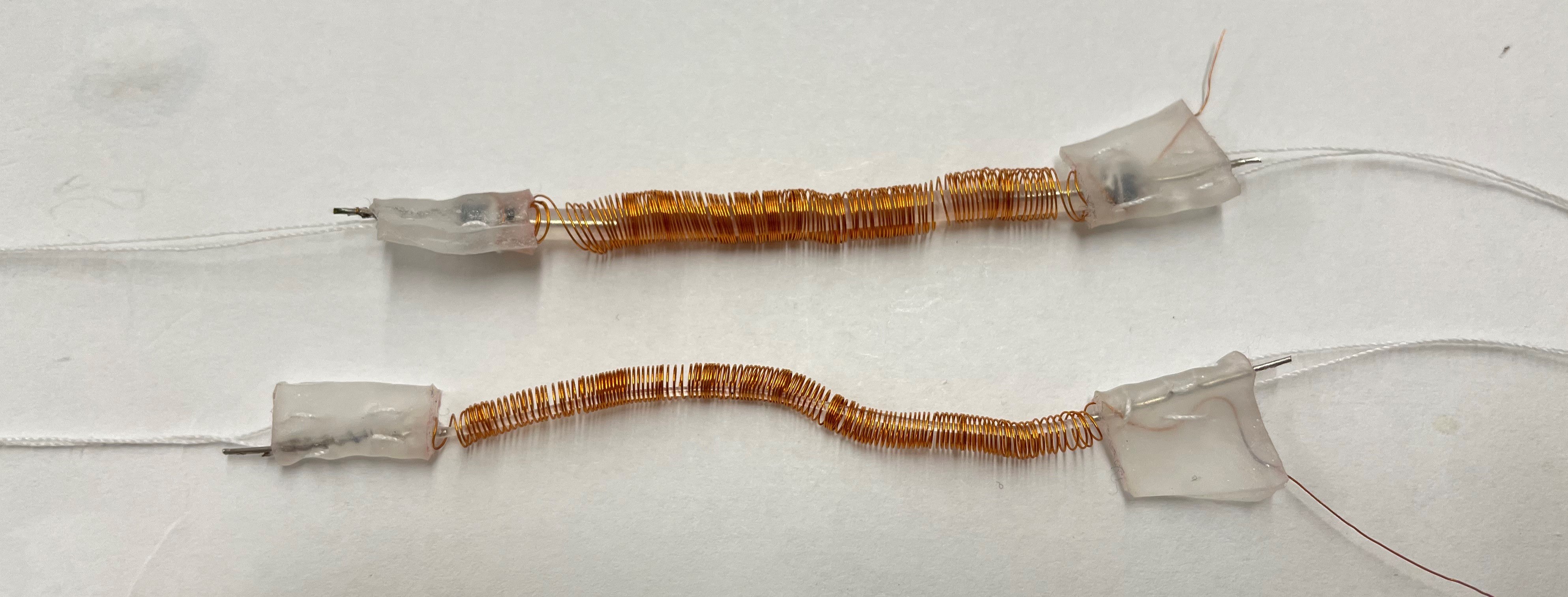
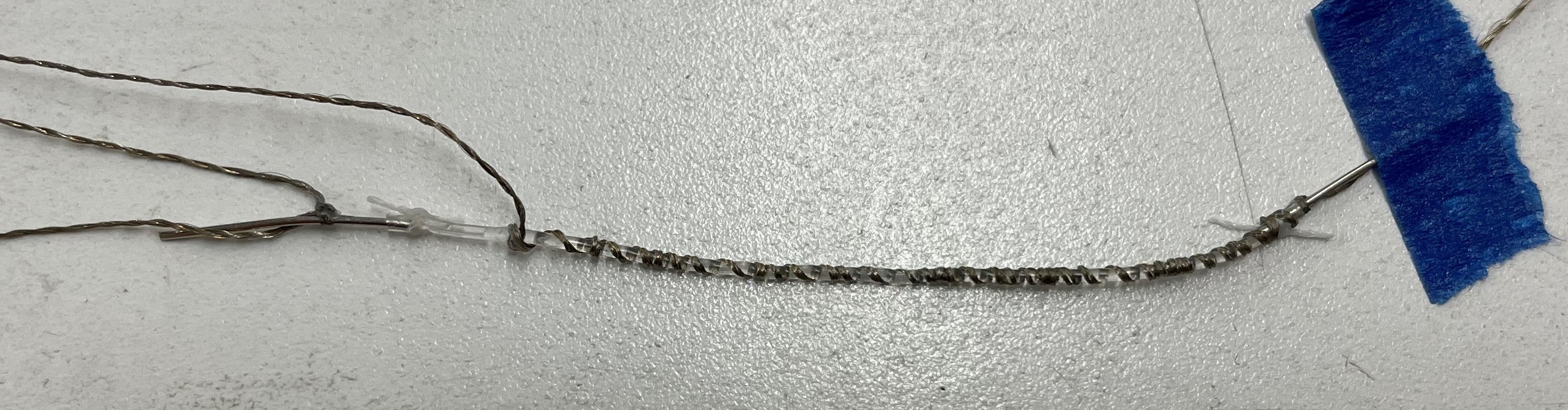
Sensor w/ wire
Sensor w/ conductive string
Continuing on my work from yesterday, I spent the day making resistive sensors with both electrodes on one side. I had tried using the conductive thread - wrapping it around the resistor - to bring the electrode connection to the other side, but these sensors were being very finicky - working sometimes but not others. Ali had the idea of using copper wire and I thought to use a small rod to create a coil before slipping the sensor inside and soldering the end.
Tuesday, July 19th
Today we tested the string setup to figure out at what angle we needed to attach the bottom plate in order for it to produce the torsion and longitudinal strain we wanted. Once we had figured it out, we attached the bottom plate to the prolate by sanding and priming the acrylic before casting it to the prolate.
Monday, July 18th
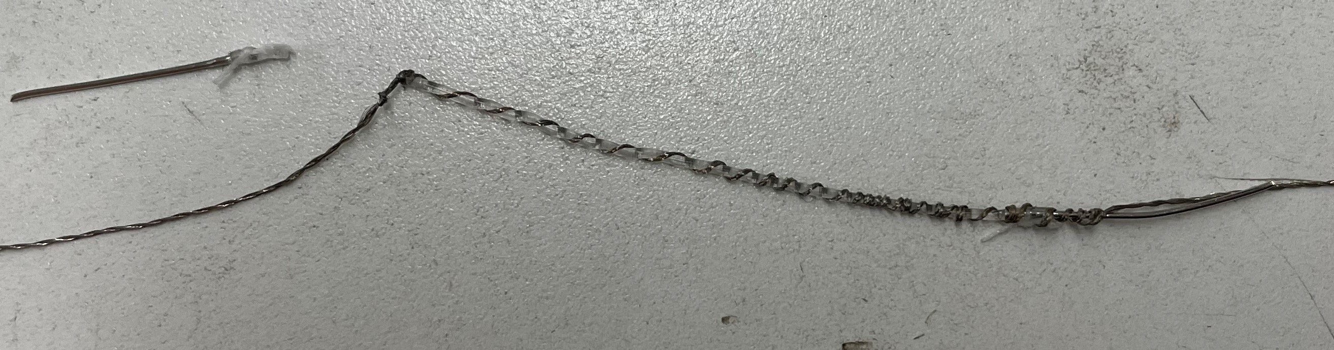
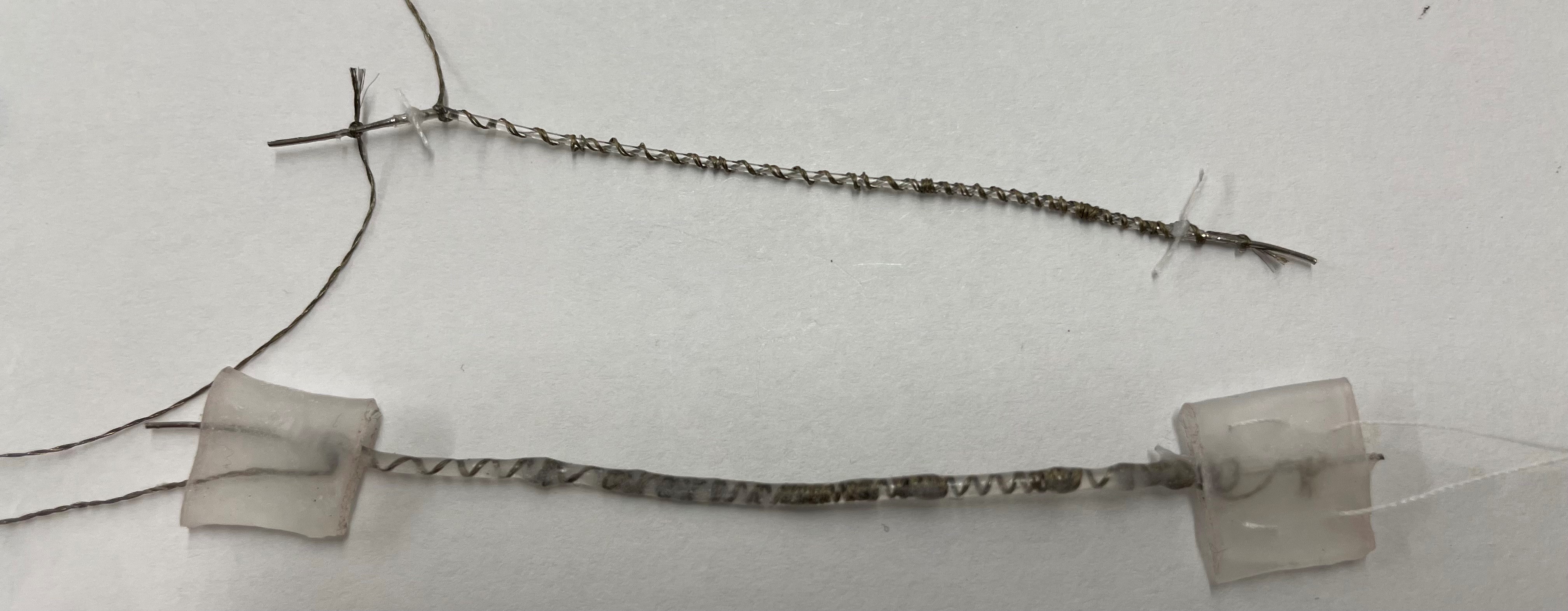
Resistive Sensor Attempt 1
Resistive Sensor Attempt 2
Ali taught us how to make the resistance sensors today. They're a lot harder to make than I initially thought. While the steps themselves are relatively simple, the parts are so small and fragile that they're hard to maneuver and easy to break. We first had to cut a length of small tube, then inject the ionic solution into the tube, before we could push pieces of nickel wire into the ends (taking care to limit any bubbles). After testing the resister worked, we tied a string around each end and applied super glue to secure the assembly. Lastly, we tied conductive string to each end. Ali wanted to try leading the electrodes both to one side to make attaching them to a circuit easier, so we wrapped one of the strings around the sensor. In order for the sensor to still be able to stretch, we needed to coil it around the tube tightly enough that it would stretch when the sensor did. The coiling took some time because the tube was so flexible and wanted to bend every time I wrapped the string around it. I was able to get the string satisfactorily coiled, but in tying the knot the tube broke. I made another sensor, but unfortunately the nickel wire detached just after I coiled the string around the tube.
Week 4
Thursday, July 14th
Cast Ring Test
Cast McKibbens
In the morning I checked on the McKibben actuators I had left to cure in silicone overnight. Where the actuator was close to the mold wall, the silicone was too thin to form a cured wall around the uncured silicone in contact with the latex balloon. Because of this, the silicone had a split line that, when the McKibben was pressurized, would open. The same thing happened to the ring actuator I had tried to cast using a makeshift mold from stacked cups. The ring wasn't fully incasing the actuator, causing the silicone and mesh to separate after a few tests.
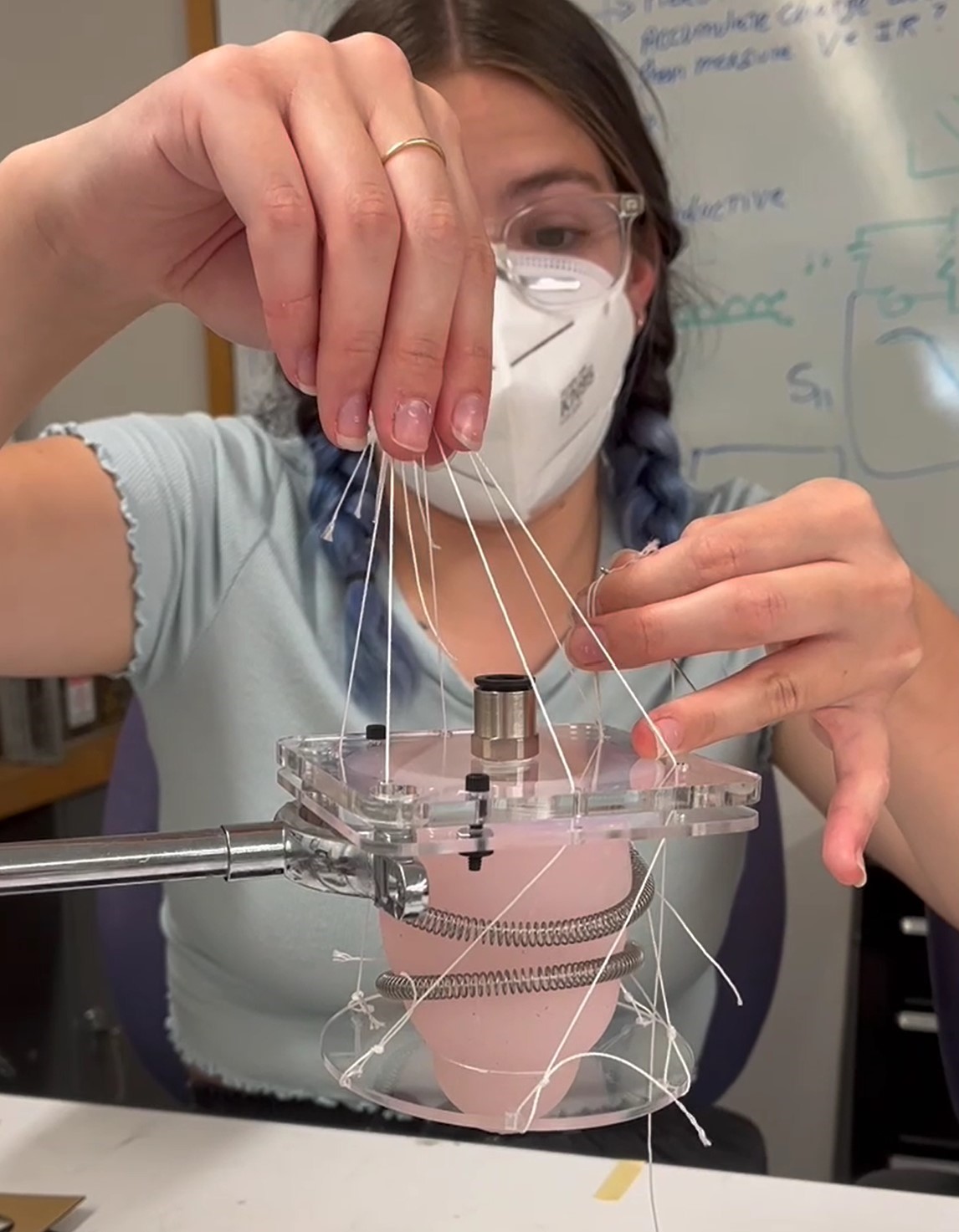
String and Spring Prototype
In the afternoon, we talked with Ali and Mark about our options for moving forward with the active phantom. We decided to try not using actuators at all. Instead we wanted to use string. We tested using a loose ring shaped spring with a string running along the inside to allow even contraction when the string is tightened. We also tried attaching strings in a helical orientation from an acrylic bottom plate to the top plate such that, when the strings were pulled, the prolate twisted. The concept seemed promising, so we plan to refine the idea and create a working prototype of the combined motions.
Wednesday, July 13th
Actuator Material Test
We came back to check the McKibben actuators we had left hanging to cure overnight to find they were still not cured. The silicone should have a cure time of only four hours, so we thought there could be an issue with the latex in the balloons interfering with the silicone's ability to cure. To test this, we mixed a small amount of Ecoflex 00-30 and 00-20 and applied a it to a small piece of the mesh and balloon we had been using. We then placed it in the oven to speed up the curing process. After a little while we checked on it to find that the silicone had completely cured everywhere except where it touched the balloon. This means that we will need to source different, latex free, balloons to use.
After lunch, we had a Cardiac Corner strategy meeting to figure out our plan for the sensor and phantom. We decided to pursue a few parallel options for the actuators and to continue testing the prolate in different scenarios. The results of our tests will help us decide what to do next.
Tuesday, July 12th

Actuator Testing
Today Heather and I worked on testing variations of our McKibben actuators. We wanted to test using both Ecoflex 00-20 and 00-30 as a coating. We also wanted to try putting primer on the McKibbens before coating them in the silicone. Additionally, we made some longer actuators that we secured in a ring shape and plan to cast into a ring of silicone to see if it behaves as we expect in when pressurized. To run out tests, we made eight McKibben actuators, two long (21.5 cm) and six short (12 cm). Once we finished fabricating them, we coated two short and one long actuator in primer and left them to dry for two hours. Then, we coated each McKibben in silicone, four in 00-30 and four in 00-20, by dipping them into a cylinder (half of a syringe) full of silicone. We then strung them on a string attached to a hanging bar. We used a heat gun to partially cure each one before leaving them to finish curing over night.
Later in the afternoon, Lawrence led us in a workshop on soldering and wire crimping. He taught us how to solder pin connectors onto a board and how to remove the solder using solder wick when we make a mistake. He then taught us how to crimp wires by first cutting and striping the end of a wire, then placing it in a crimping pin and using a crimping tool to secure the two parts together, and finally pushing it into a plastic connector.
Monday, July 11th
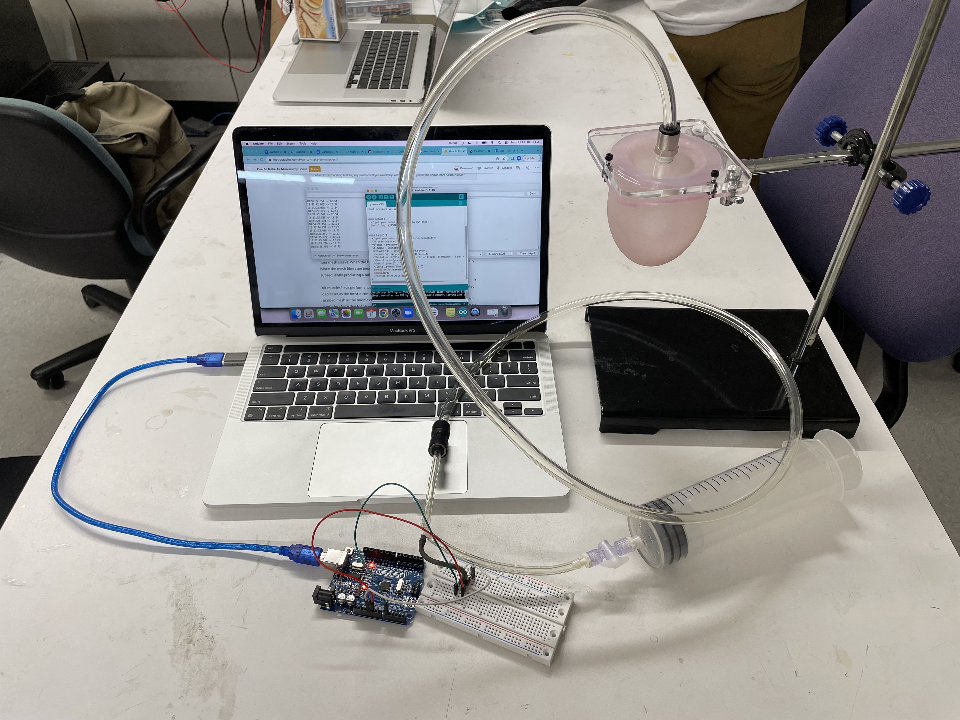
Prolate Setup w/ Tubing and Arduino
The tap we needed to finish the prolate setup came in today. We tapped the top acrylic plate, carful not to crack the acrylic in the process. We then attached the tubing, including a syringe to fluctuate the volume of air in the prolate and a sensor to read the pressure of the system. Heather attached the sensor to the Arduino and used a MATLAB script that Ali gave us to graph the pressure in real time. To make sure there weren't any leaks in the setup, we pumped air into the prolate and took note of the pressure. After a little while, we checked that the pressure hadn't changed, meaning there were no leaks in the setup. We then tested that the pressure in the prolate was the same for a given volume each time we
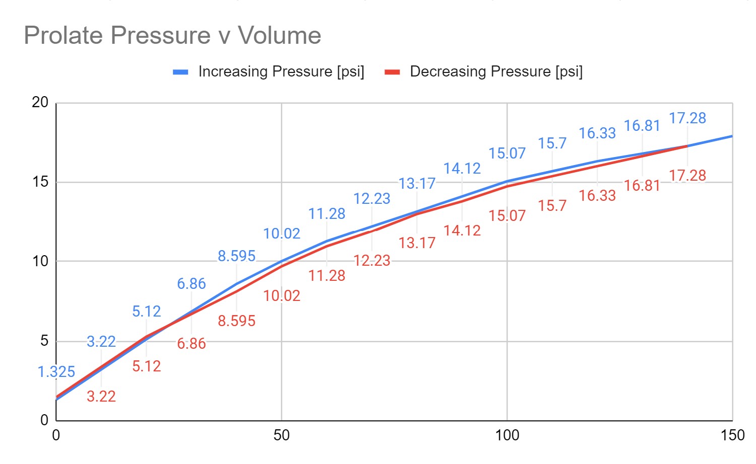
Prolate Pressure vs. Volume Graph
applied that volume to the setup. In running this test we plotted the pressure and volume on a graph to see how they were related.
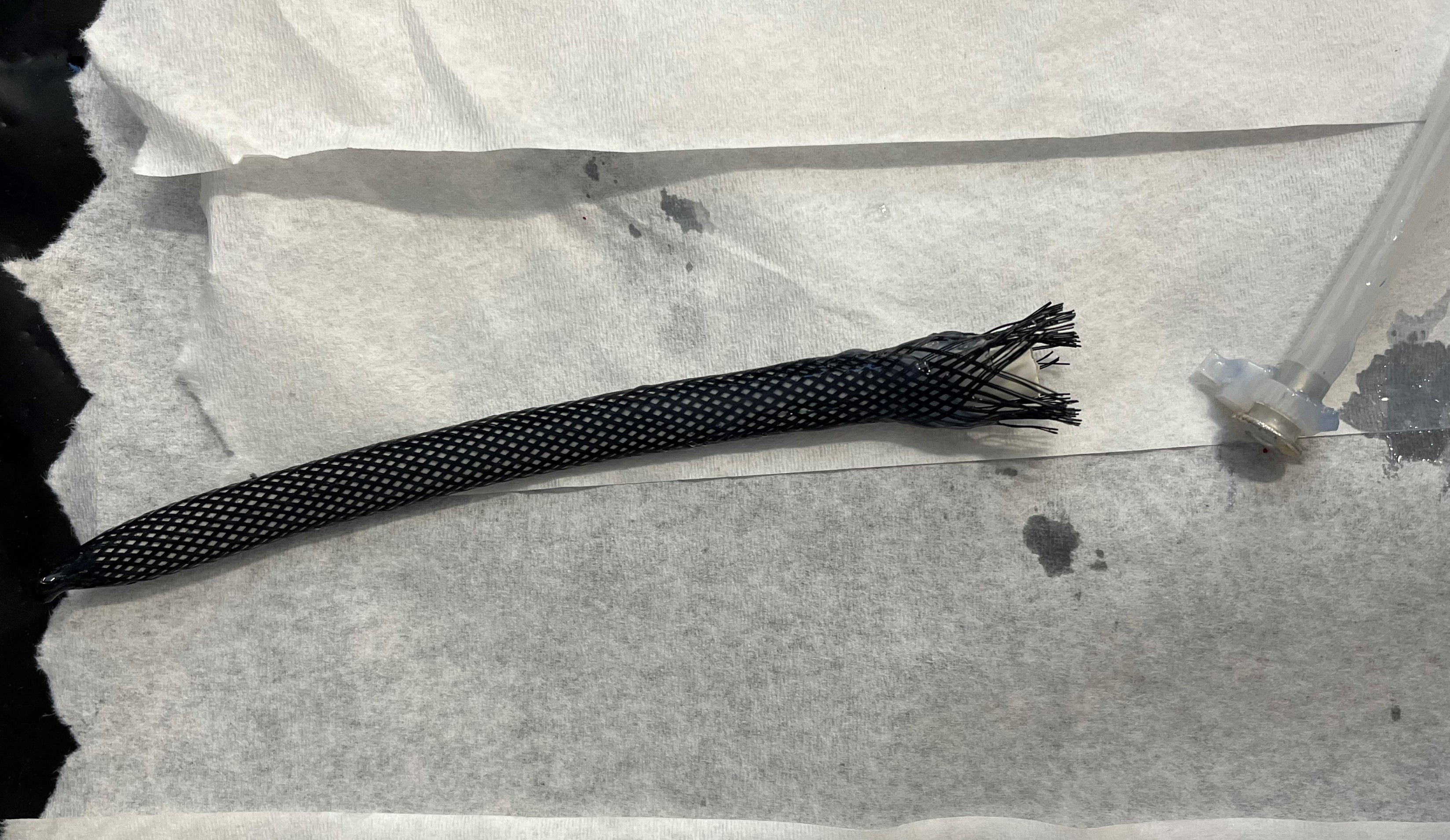
Later, we worked on compiling a list of all the materials we need to fabricate the McKibben actuators so that we can order them. In rereading the Ellen Roche paper describing the fabrication of their DCC device, I saw they had compressed the mesh and heated it to prevent fraying on the ends. Since this was an issue we had when first making our McKibbens, I wanted to try to replicate the process. I found a metal tube and some heat shrink tubing, and Heather and I heated up portions of the mesh around the metal tube while protecting the portions we didn't want to change with the heat shrink. We accidentally over heated one part, causing it to melt a bit. However, even with this melting, the tubing was much less prone to fraying on the ends as we inserted a balloon. I think we will use this technique when fabricating our McKibbens for the actual simulator.
Week 3
Friday, July 8th
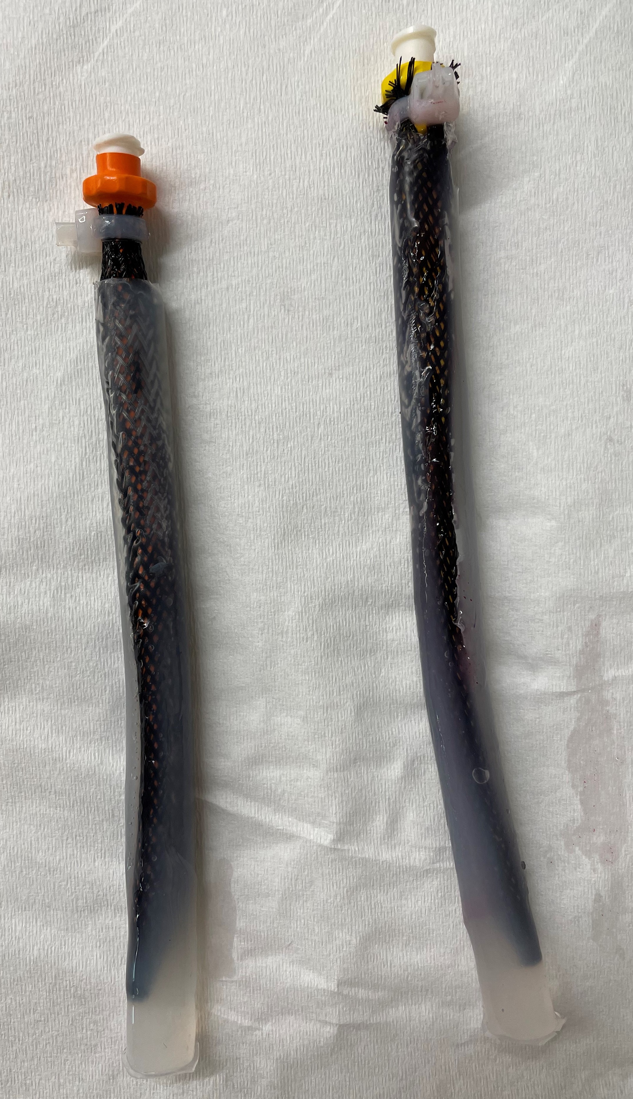
Failed Silicone Coated McKibben Actuator
We went back to thinking about the actuators today. We made six more McKibben actuators, but only three were successful. We found that the diameter of the balloons we were using was slightly too large to fit onto the pneumatic coupler without folding, causing air leaks. Our solution was to place a small dental rubber band around the coupler before placing the balloon and mesh around it and tying it off with a ziptie. We were confused by the wording in the Roche paper describing their PAM fabrication process, but after reading the supplemental materials carefully again, we
Silicone Coated McKibben Actuator
realized they had coated their actuators in elastomer including the mesh. We were concerned that this coating would affect the performance of the actuator, so we decided to run our own test. Heather and I took two of the actuators we made and rolled them in Ecoflex 00-20 silicone. We then used a heat gun to cure the silicone while we slowly rotated the actuator. I had tested my actuator before and after we coated it in silicone, and it was able to contract 20% from 15 cm to 12 cm both coated and uncoated. This showed us that coating the actuators in silicone does not affect their performance, meaning we can cast our silicone phantom directly around the actuators without concern for the motion.
We also attached our silicone prolate to the bottom plate of the acrylic holder. To do this we first used sand paper to roughen the acrylic where it would be bonded to the silicone. Then, we applied a primer to the surface and let it dry for two hours. Finally, we applied a layer of Ecoflex 00-20 to the plate and placed the prolate in the holder before leaving it to cure.
Thursday, July 7th
Prolate Setup w/o Tubing
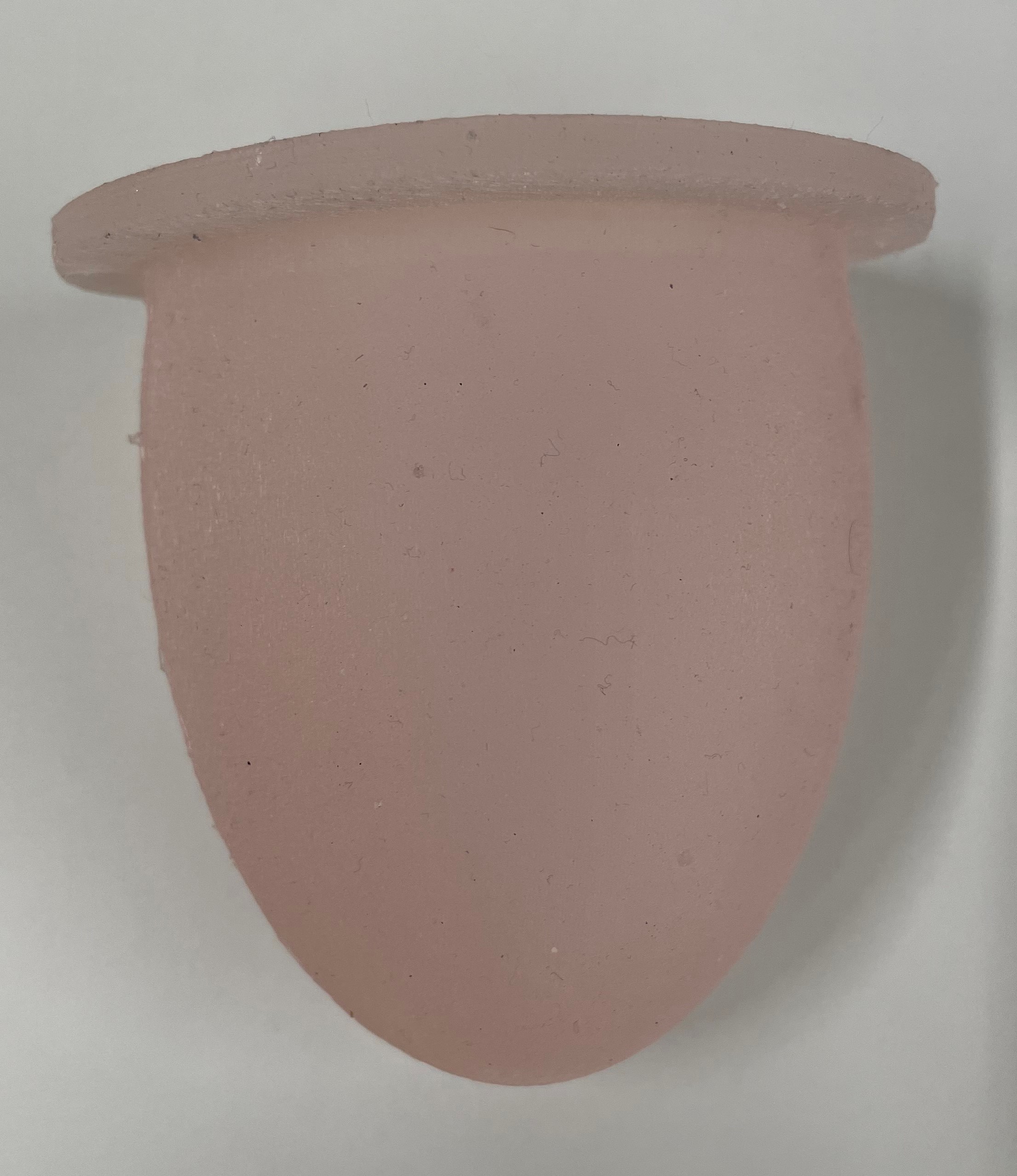
Silicone Prolate
Today we cast our first prolate! We followed the steps that Tony had told shown us during the casting workshop. There were two fairly large bubbles when we removed the prolate from the mold, one on the rim and one near the air hole. I was able to fill them in by mixing some more silicone and putting the prolate back in one side of the mold. The prolate didn't fit perfectly back in the mold the second time, so there was some material sticking out. I waited for the prolate to finish curing and then trimmed away the excess material.
Wednesday, July 6th
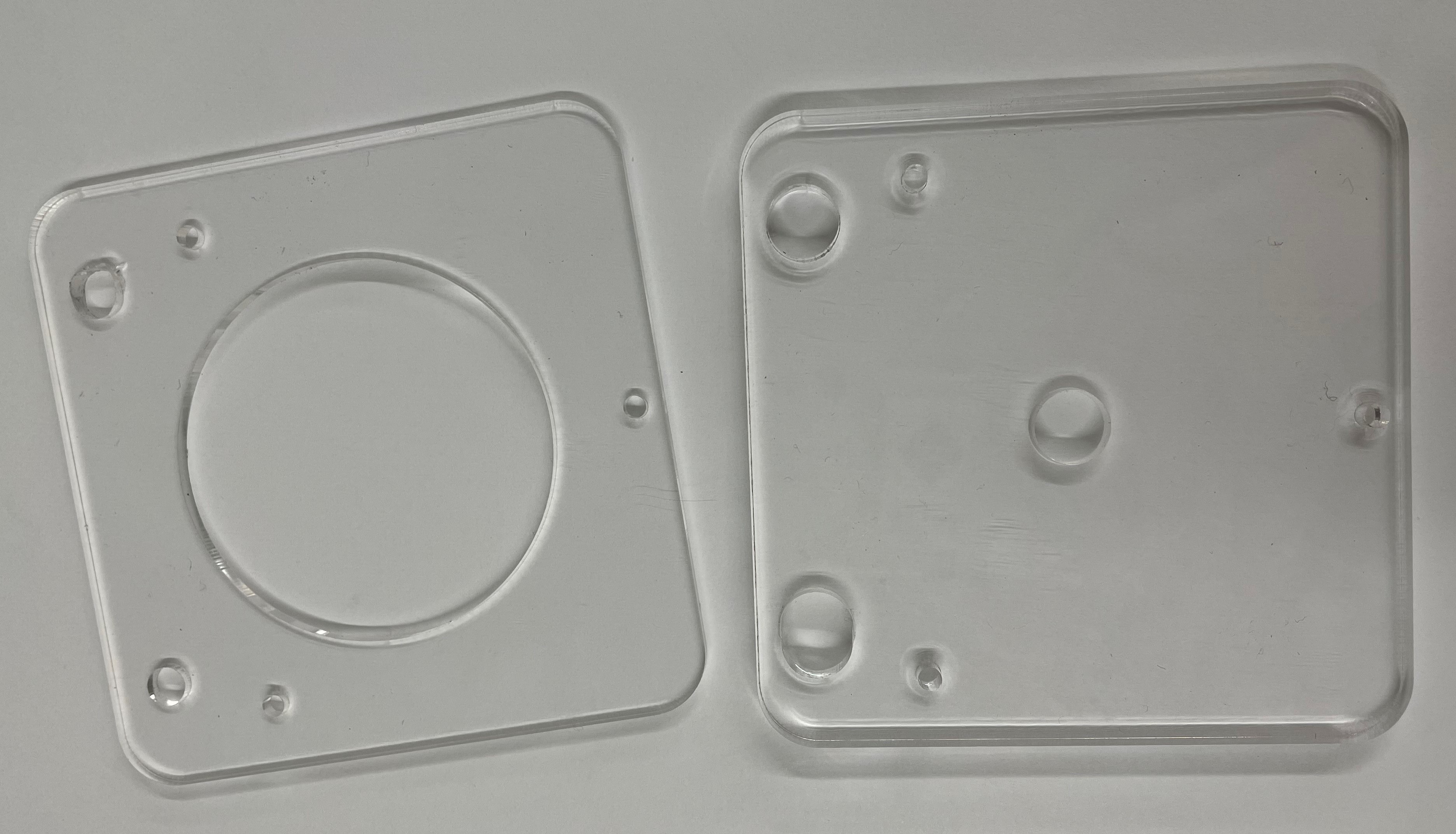
Acrylic Plates
Today Heather and I cut the acrylic plates for the prolate holder. Our measurement of the distance between the mounting screws was slightly off, meaning the screws wouldn't fit. We adjusted the CAD model to turn on of the holes into a slot to ensure the plates will fit if we recut them, but we didn't want to waste the material we had already cut. To avoid this, we used the drill press to adjust the holes slightly to allow the screws to fit.
Prolate Mold
We also got our 3D printed prolate mold at the end of the day. We didn't think about specifying a less dense infill, so the part was printed at 100% infill. This means the part is fairly heavy, and use more time and material then was necessary. We learned our lessen and will make sure to specify a less dense infill or design the more to be hollow in the future. Heather and I looked into more articles for the informal literature review, and Heather found a paper discussing a biorobotic hybrid heart. The paper describes a different type of pneumatic actuator that we think might be helpful, but we have some concerns about the shape of the actuated fPAM that we plan to talk to Ali about when she gets back tomorrow.
Tuesday, July 5th
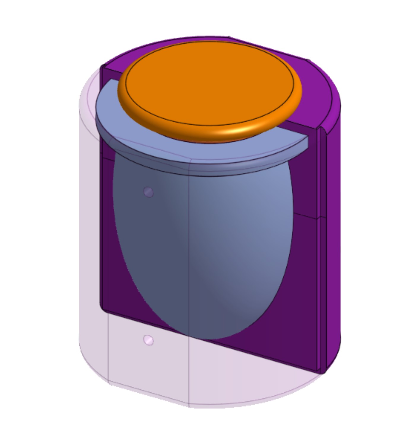
Prolate Mold CAD
McKibben Actuator
Today I focused on designing the mold for our initial prolate cast in Onshape and started the 3D print for it to be ready to cast tomorrow. Heather and I also made a McKibben actuator using materials we found around the lab to practice the fabrication process. At the end of the day, we worked more on the informal literature review.
Week 2
Wednesday, June 29th
Ring Practice Cast
Today I finished casting my practice ring. There was some flash, but other than that, it looked good. There were no issues with air bubbles or the mold not filling correctly, and now I have a cute ring I can wear. I also attended the medical device meeting with Mark. I got started on compiling an informal literature review of dynamic heart phantoms to make sure were pursuing the best path forward. The main ideas we have right now are to either make a silicone cast heart with actuators implanted that when activated will cause the phantom to contract and twist. Alternatively, we could make a silicone cast phantom with external motors and pistons attached to cause the contracting and twisting motion.
Tuesday, June 28th
Practice Mold
Today I researched the material properties of the left-ventricular myocardial to find the best silicone casting material to match the human heart. I reached out to Fikunwa O Kolawole, a PhD student with the Cardiac MRI Group who is working on a clinical method to measure myocardial thickness, and they helped point me to reliable sources covering the topic. I also spent time working through Tinkercad tutorials to learn about circuits and Arduinos and practicing creating molds in Onshape. I finished the day by starting a 3D print for a ring mold, a practice cast to get me familiar with the process.
Week 1
Friday, June 24th
The power came back on! Today I attended the weekly lab meeting, UV laser cutting workshop, Onshape workshop, and silicone casting workshop. Tony also taught me about using the CNC to fabricate the gecko adhesive.
BDML Summer Kickoff Retreat
Wednesday, June 22nd
Today we went on a lab retreat to the beach and a campsite. We spent the day getting to know each other, cooking and eating, and hanging out. In the afternoon we did a goal-setting exercise. Each person wrote their summer goals, research related and/or personal goals, on a big poster and presenting it to the group. I thought it was a helpful exercise both for each of us individually to plan our summers but also to further get to know each other and what each person is working on this summer.
Tuesday, June 21st
I spent the first part of the morning reading up on the human heart and cardiac cycles in preparation for working on the benchtop left-ventricular simulator. Ali sent me a slide deck with an overview of the cardiac project and links to relevant reading, so I spent the rest of my day working through those resources. In the afternoon, Dane gave us a safety tour. There was a power outage later in the afternoon, causing us to leave the lab early.
Monday, June 20th
Today was my first time in the lab. Mark got me set up on the BDML Wiki, I attended the SURI kickoff meeting, and I completed the STARS safety trainings. Also, Ali gave me an overview of the intracardiac medical device project that she and Ileana are working on.