new web: http://bdml.stanford.edu/pmwiki
TWiki > Rise Web>RisePlatform>QuadraRiSE (13 Jul 2007, MarkCutkosky)
Links
Page about Sal's alternative control: RiSEVoltStateControl Page about tree climbing with current robot: TreeClimbingProgress Page about body analysis for tree climbing: TreeRobotDesignCurrent Status
Experiments testing the power in RiSE's motors (March 26, 2007)
Tests I ran (the following is from Clark's email):
| Test | Crank Direction | RiSE orientation |
|---|---|---|
| #1 | Positive | On belly |
| #2 | Negative | On belly |
| #3 | Positive | On back |
| #4 | Negative | On back |
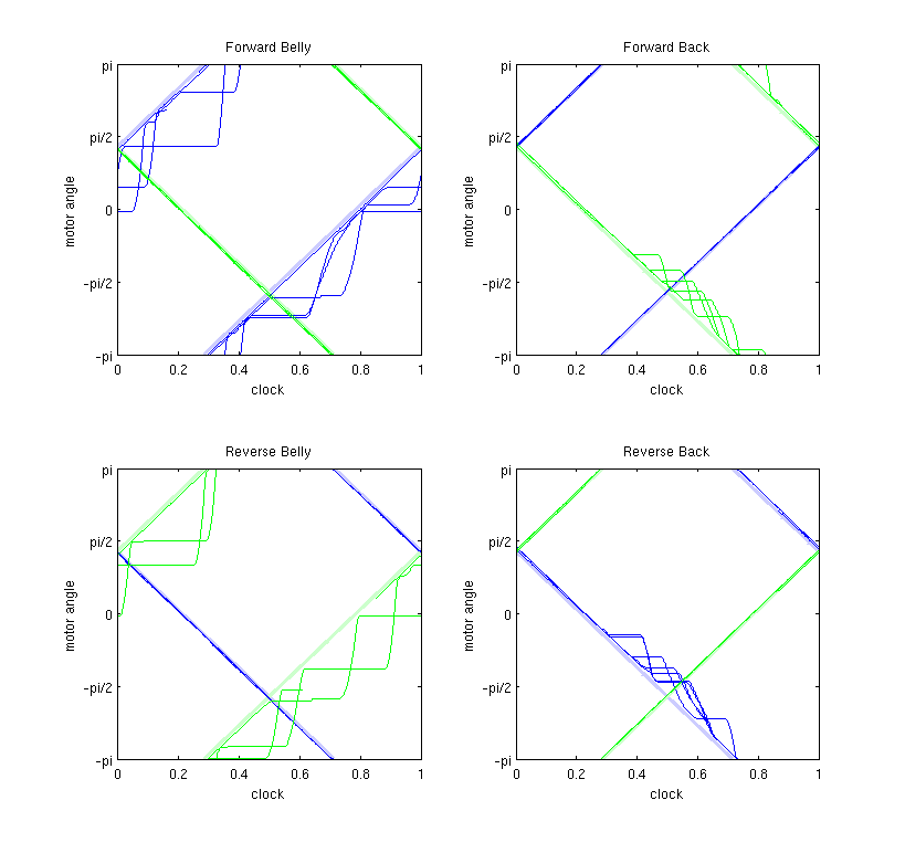
Note by Clark: It should be noted that when on its back, the available range of motion of the wing DOF is small, thus the smaller movement by the drooping motor. So that explains one difference between tests #1 & #2 and #3 & #4. Can we attribute the "preference" (a.k.a. when the motor moving in reverse is between -pi/3 and -pi) for failure angle in #3 and #4 to mechanics? Why are tests #1 and #2 seeming to fail relatively anywhere in [-pi,pi]? (I might suggest redoing #3 and #4 with RiSE on its side, and the wing angles at 0 degrees, hanging weights from the legs closer to the ground). It should also be noted that the motor that stalls in each case is the one needed to stall in order for the wing angle to droop.
-- ClarkHaynes? - 29 Mar 2007
One other note: There are faint blue and faint green lines on this plot (assuming you usedmotorlines.m), perfectly on the target line slopes. This means two things: (1) my bug fix for logging motor target positions worked, and (2), the motor targets are totally correct, in terms of position.
-- ClarkHaynes? - 29 Mar 2007
- I tried making
RiSE do pull-ups by just its front legs. It pulled itself up about halfway through the crank change in Stance but then stopped. Clock speed was 0.051.
- I repeated Clark's experiments with hanging weights on the legs, and did some others. I made a movie of what I did and it's posted here:
- If the clock is stopped the legs can support 500g with only drooping about 1cm.
- If the legs are moving with clock speeds ranging from 0.005 to 0.122, the legs start drooping with 200g added to them, but they return to their original trajectory after drooping about 60 degrees. With 400g added to the legs they cannot lift themselves back up to the original height anymore. After we had been hanging weights on one of the legs for a while, it started drooping with only 100g.
- If the legs are moving and you pull on the legs in the crank direction with a spring scale when the crank is in the Stance position, they stall at around 8-10N. This seems to be independent of how much weight you put on the legs in the normal direction! Tests were done with 0-300g hanging off the legs, and in all cases the cranks were able to pull 8-10N. Note that our robot weighs about 2.9 kg, so indeed it should not be able to do a pull-up if each leg can only pull 10N at most!
- Stance, Detachment, Flight, Attachment were set in the
ClockMap to each take 0.25 percent of the time. - In the
LegTrajectory, all of them were set to have no wing change and -0.25 crank change.
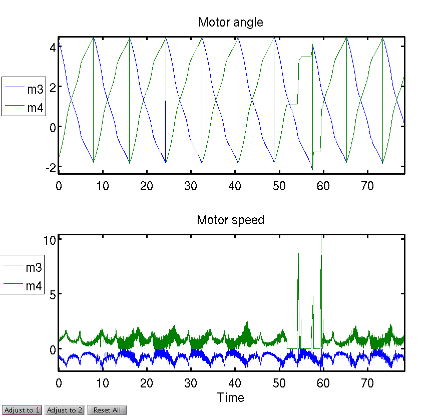
The following plot shows motor angles and speeds when 100 and 200g weights were hung off legs. I believe there was no load on the legs from times 0-10 or 15 seconds, 100g on the leg from ~15-45 seconds, and then 200g on the leg from ~50-65 seconds. From ~65 seconds to the end it had 100g on it again. As you can see, motor 4 stops at various crank angles.
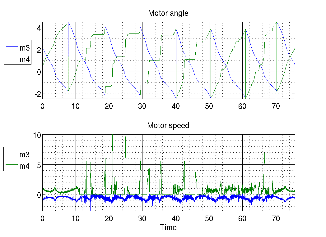
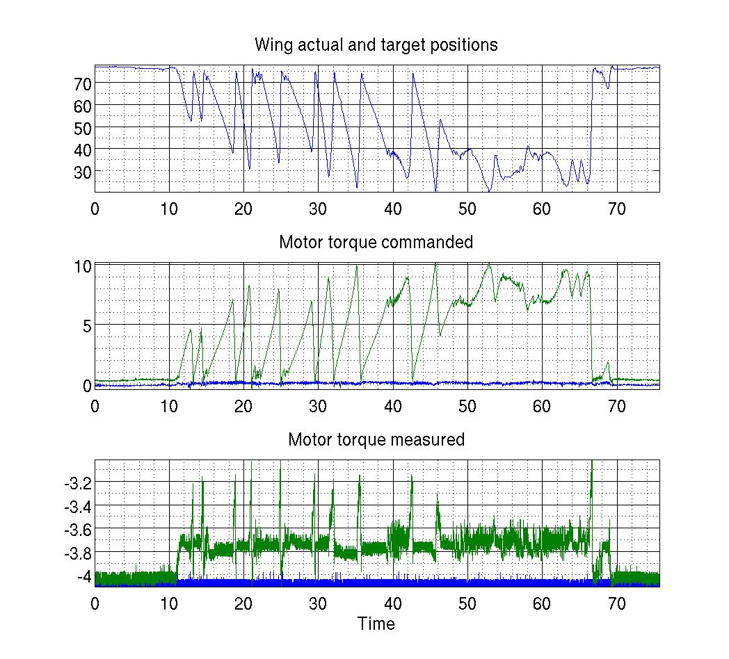
The following plot shows wing angles and torques for 300 and 400g weights. In the movie, this was when I was seeing the maximum weight the legs could hold and still return to their original trajectory occasionally. If you recall, with 300g on the leg it would droop and then recover but with 400g it could not lift itself up and the leg dragged the weights around on the table. This shows the motor angles and speeds, wing angles, and motor torques during that experiment. The leg had 300g hanging off of it from about 10-44 seconds, and 400g from 44-66 seconds (when the wing doesn't return to the "up" position ever).
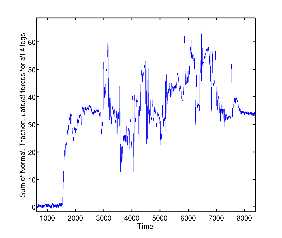
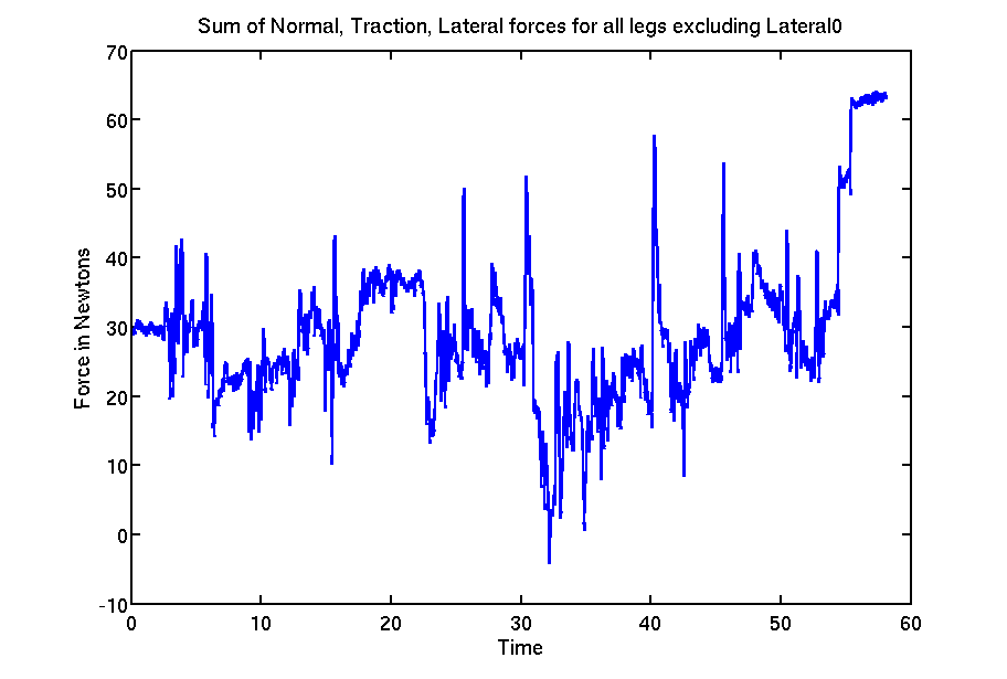
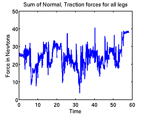
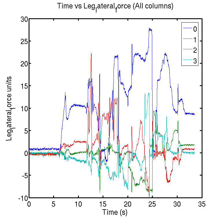
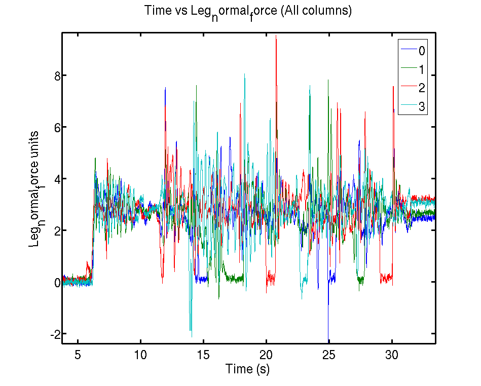
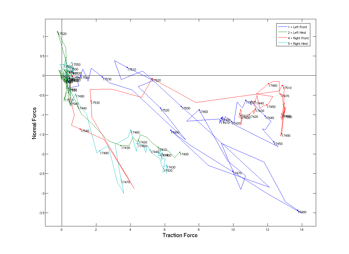
Experiments determining total force generated by robot (Feb. 1, 2007)
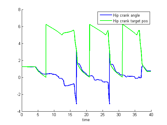
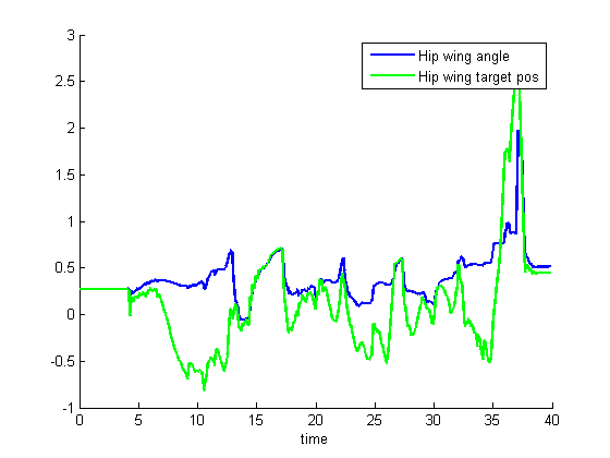
desired vs actual hip and crank angle for the stanford tree gait- crankangle.png:
- hipangle.png:
- Run1: Total forces for entire robot:
- Run2: Total forces for entire robot, minus a weird lateral force measurement:
- Run1: Just the normal and traction forces:
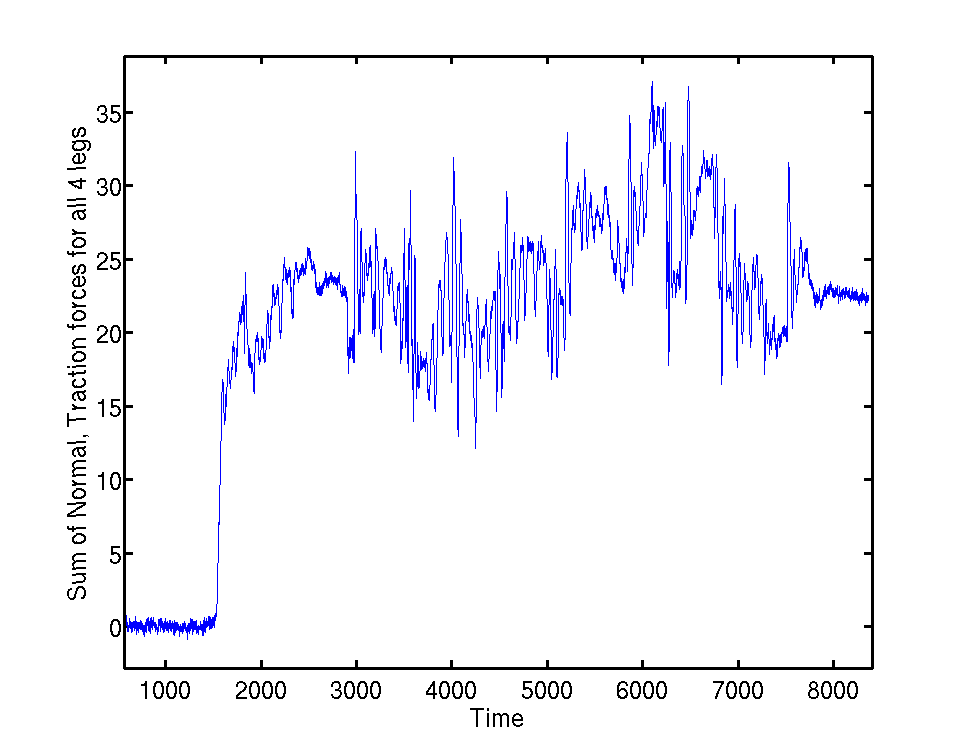
- Run2: normal + traction:
- Run1: Just the lateral forces, they look larger than they should for leg 0, at least..:
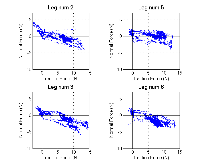
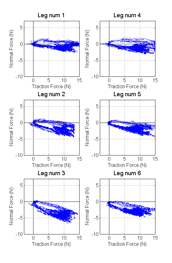
- Run1: For comparison, just normal forces for all legs. This also allows you to see the steps the robot took, and how when it is not moving the forces are accurately controlled to 3N/leg:
Week of August 21, 2006
8/22/06
Sangbae toes - shingles, max speed= 0.195. I don't really know why there is such a speed increase. We repaired/adjusted the spines on the toes before we left, but I can't believe that is the only reason. Also the shignles could be different, but they look the same to me. I just remembered that I changed the tail angle as well. There used to be 4 or 5 washers in the tail. Now there are three. This reduced the wing offset from 14 to 9.Week of July 24, 2006
7/27/06
Re-ran the tests on shingles with sangbae's toes at 90deg. We saw some definite improvement, but it fell after 17 successful steps. The data shows what is starting to appear to be a "typical" failure. All four legs appear to be well engaged. One leg moves off the wall (more often the rear leg, but that could just be a coincidence at this point) and the other leg on that side begins to slip. We see several "micro" slips occur before it becomes too much and the other side of the robot fails. See also the "Plots with commentary showing what happens when the robot fails" below for more information about failures. Also, we realized that it is important to calibrate the Force sensors with the robot oriented vertically (in the climbing position), because the feet have some mass and there will be offset errors if the robot is calibrated in any other orientation.7/26/06
We ran the robot on three outside surfaces yesterday. The results were not that promising. You can see a video of our performance here: QR062507experiments1.avi: divx (Note that I realize that it says my name in the title. This was obviously a mistake and an artifact of the default state in imovie!). We are also looking at some of the force data. On a first pass it seems as if although a foot may be "in stance" there are times when it is not supporting any load. When another foot then comes off the ground, the robot fails since only two feet are supporting the robot. Perhaps we inadvertently disabled the pawing function? Or perhaps we need to just ensure that a foot does not detach until we are sure that the other feet are carrying a load. Here is another video that shows some upclose shots of the feet. Note that we have two different types of feet on the robot. The front left foot uses Sangbae's design. The other three use Alan's design. It appears as if the size of Sangbae's toes is not appropriate for the surfaces that we are climbing. However, the there is good engagement. Perhaps a redisgn with larges spines would be appropriate.- QR062507expclose2.mov: Uses quicktime, I believe you need quicktime 7 to run it.
 compare this to the data from the library endurance run:
 A couple interesting points.
 - The frictional-adhesion model is applicable to spines, to a point. The spine/surface contact is based on friction, and so the harder you pull down the more friction force you can sustain. There is a limit to how hard you can pull based on the asperity or spine breaking/bending. Also there is some angle at which you pull away from the wall where suddenly the normal force is not sufficient for the friction force you are depending on, and the spines will slip off the wall. This angle will vary within the foot depending on the individual spine/surface contacts. However, there are also dynamic effects to the frictional adhesion model with spines: if the spines are moving too quickly (sliding friction) they will not be able to gain purchase on asperities. Furthermore, since the spines have mass they have a tendency to bounce off the surface if they are moving quickly. So you have to slow the foot down a little when attaching it to the wall (at least, you can't be moving super-fast).
- Leg 2 was the leg that failed in this test (Front left), although this is not evident from these plots. Perhaps the spines are just too small for this surface? However, results from other tests indicate that the front left leg can hold more load than the other designs. This could be a result of the hard stop that is on the larger toe designs, but is absent from the smaller spines.
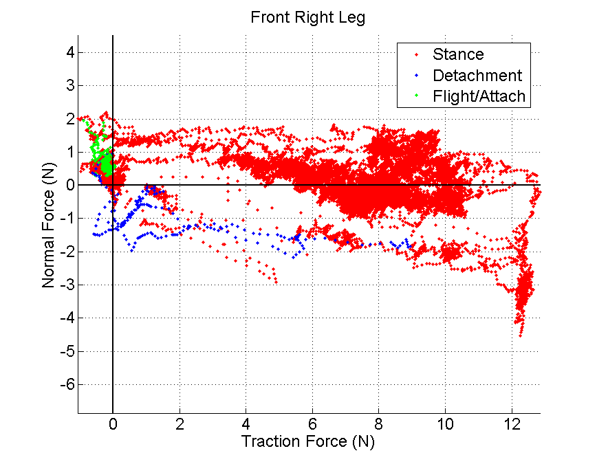
- There is non-neglible friction in the flight/attachment stage. This could be a good method of tuning the gait, since a gait change should be able to eliminate this. - Note this appears not to be a problem if we cut out the first four steps of the robot after it is placed on the wall.
- Similarly, the detach gait could be modified to have a smoother, zero-normal force detachment.
- The front right leg is spending too much time in positibe normal force and both rear legs have too much adhesive force.
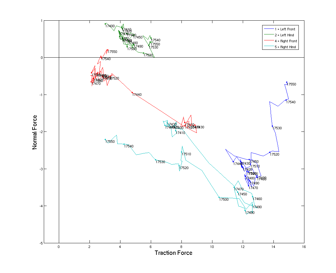
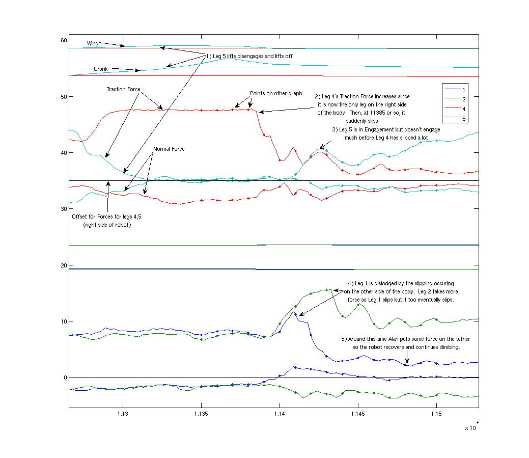
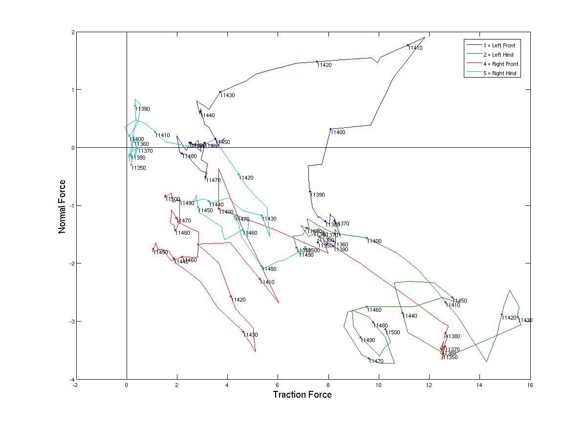
Plots with commentary showing what happens when the robot fails
These plots are in pairs, one showing the forces and wing/crank angles vs. time, and the other showing the forces on a F_traction-F_normal plot. The F_t-F_n plot has the points labeled with numbers which correspond to times on the force-vs-time plot so you can correlate the data. The force-vs-time plots are annotated so you can see the progression of events that led to the robot falling. The first pair of graphs shows a phenomenon we observed several times while climbing a stucco surface that should be really easy to climb, since the stucco grains were quite large (3mm). Essentially, one of the feet came off the wall for unknown reasons. Then, the other foot on the same side of the robot was scheduled to Disengage and take another step, and it did so even though the other foot on the same side was not carrying any weight. This caused the robot to fall since now neither foot on that side was carrying any weight. The code should be changed so that the robot doesn't take a step if it sees that the attached feet on the same side are not carrying any weight, and instead it should try re-attach those feet.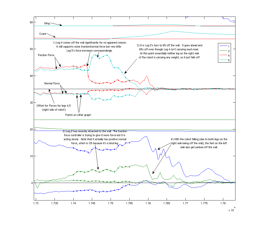
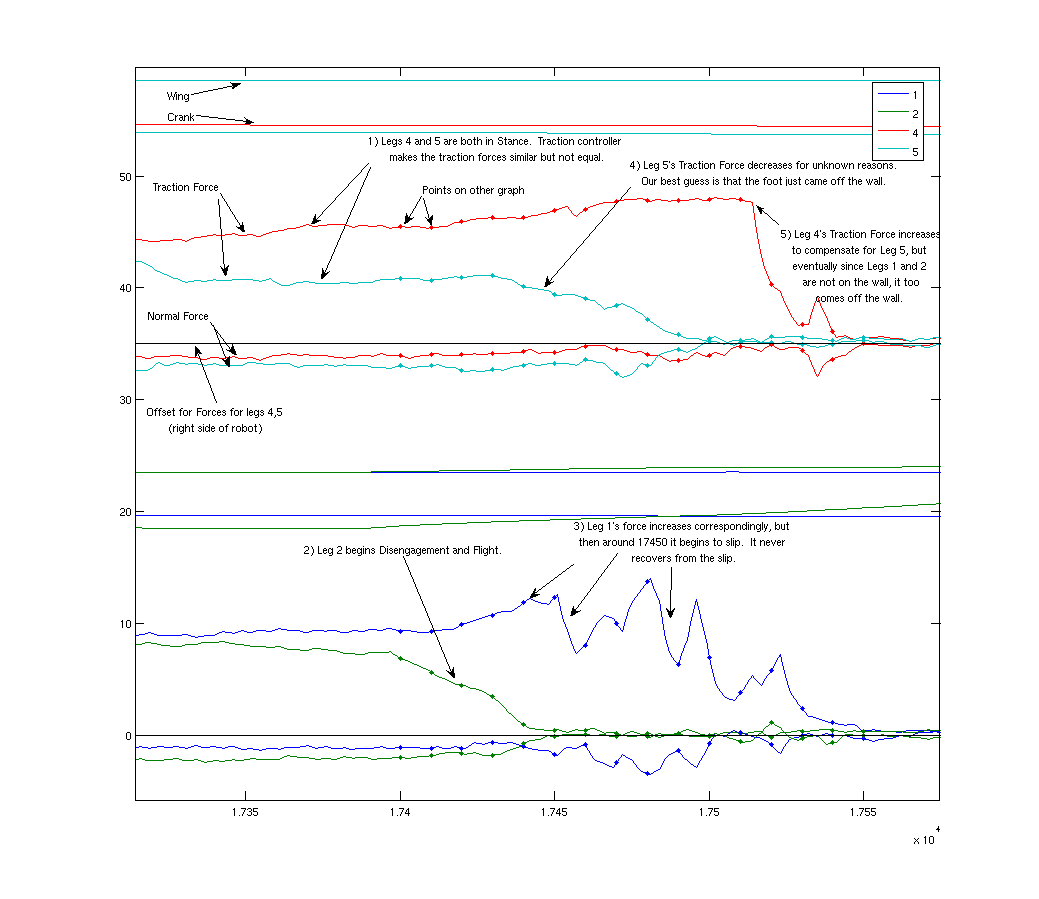
 The next several plots were done on a pebbly wall with a lot of fairly jagged 1-2cm rocks embedded in concrete. These plots show that sometimes, one foot is in flight and the other foot just suddenly fails for no apparent reason. Perhaps sometimes the foot/wall contacts are failing because the leg in flight jostles the robot... sometimes the legs go through flight quite quickly.
Week of July 17, 2006
7/20/06 After taking a closer look at our climbing performance, we noticed that the wall was at approximately 80 deg. We re-ran the tests at 79deg and at 90 degrees. We were able to successfully climb the 79 deg, but we failed at 90. We also had a slew of failed runs. Its amazing how much difference slight changes in the feet make to the climbing performance. After a few failed runs, we adjusted the pitch of the toes forward a couple of degrees and we saw immediate improvement. We also tried some new toes out (actually old toes on the new ankle - see SummerUpdates) and found it to be a superior foot for the asphalt shingles. It is doubtful that it would be able to climb the "library" surface well because of the size of the spines, but who knows.- QuadraRiSE06-20-07divx.avi:Climbing 79 deg
- QR-Fail90degdivx.avi: Failing at 90deg
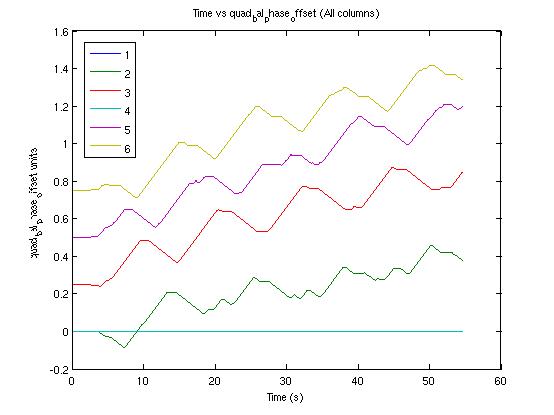
- quad_bal_phase_offset.jpg:
- In the current configuration, with mm_update_period set at 3000, only two of the four LSANs can be connected without the startup routine failing. It is not a function of the LSAN wiring as it does not matter which two LSANs are connected.
- If we connect the third RMC then we can connect all 4 (or 6 if we wanted) LSANs and the supervisor will start up properly. However, if all 3 RMCs are connected, we cannot switch out of calibration mode. If only two RMCs are connected then the code recognized this and will allow us to switch modes.
Ideas, requests, problems regarding TWiki? Send feedback