new web: http://bdml.stanford.edu/pmwiki
TWiki > Rise Web>RisePlatform>TreeRobotDesign (13 Jun 2007, MattSpenko? )
-- MattSpenko? - 04 Apr 2007
mu*F_normal >= sqrt(F_tangential^2 + F_y^2)
This is for the Front feet. Notice that its fairly easy to decrease the needed coefficient of friction by moving the front feet around the tree more. This makes sense since as we are moving around the tree we are using the gravity to help keep us on the tree as opposed to dragging us off the tree.
This is for the Rear feet. The results are much different than with the front feet. Here increasing the feet too far around the tree results in a higher mu since you are essentially losing that "jamming." Thus, it is better for the rear feet to stay at the front of the tree.
This is for Both feet. Essentially it is the minimum coefficient of friction that is necessary for both front and rear feet to remain stable. Notice that we need to squeeze in a lot and wrap around most of the tree to get reliable climbing. One question to ask is if this is the case, how have we climbed trees before? Two reasons: First we had six legs, and second the large ridges of telephone poles and oak and pine trees effectively make the tree's radius much smaller than it actually is.
For the Front feet.
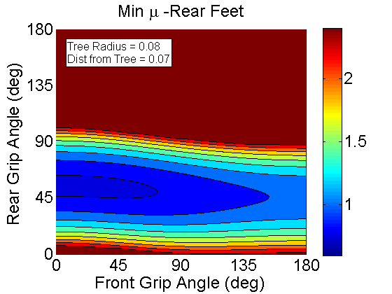
 For the Rear feet. At low rear foot wrap angles (less than 30, mu decreases as the front foot angle increases - its just not shown in this graph since mu is limited to 2.4 here.).
For Both feet. Shows that an optimal foot placement is around 120deg for the front foot and 60 for the rear foot. One question to ask is what the tail is doing in this situation. Is is helping or hurting us? Large animals that climb don't use their tails the way a gecko does. Squirrels don't use their tails for pitch back prevention. In fact the tail might be hurting us since it doesn't let us effectively jam on the wall
 This is what happens if we really differentiate the legs and have the rear legs provide propulsion only:
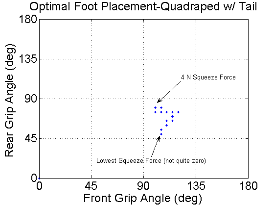
 So the question may be: What is the optimal foot placement for a given robot configuration as a function of the squeeze torque.
The answer is:
So the question may be: What is the optimal foot placement for a given robot configuration as a function of the squeeze torque.
The answer is:
 When we add in the tail, the points change a bit:
An analysis of the kinematics of the robot for climbing trees
For related topics, see also:Goal:
To determine the proper shape and kinematic structure the next version of RiSE.Hypothesis:
The robot will need to be a "tree hugger" to a certain extent. As much as possible, the robot will need to move its feet around the tree. We make this hypothesis by looking at the climbing habits of larger (RiSE size and weight) animals such as cats, bears, etc. and notice they tend to climb by wrapping their front feet around the tree and use their rear feet to propel them up the tree.Pre-analysis:
The dimensions of a quadrapedal climbing robot in relation to a tree of radius r is shown below.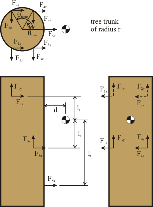
Analysis:
We assume that when the robot is not in a dynamic climbing state, it must be stable on the tree. Thus given a minimum coefficient of friction, we ask the question of where the robot should place its feet and how much should the robot "squeeze" in to maintain stability. Since the robot is over-constrained we need to use the pseudo-inverse to find the forces that it would need to apply to maintain static equllibrium with no internal forces. This solution has all forces in the Z-direction (the robot squeezing in) equal to 0, and thus we are free to set those forces to whatever we want. We then check the solution to find the minimum coefficient of friction such that the forces do not violate the following constraint equation:mu*F_normal >= sqrt(F_tangential^2 + F_y^2)
Results
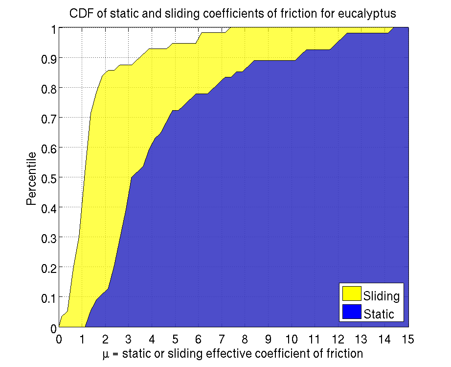
Alan did a nice analysis of the coefficients of friction actually achievable on the trees we have in our lab, using dactyls. In summary, we can get reliably get a mu of about 1.7 about 90% of the time, but see the plot below for the entire result: Coefficients of friction on eucalyptus tree:
Current QuadraRiSE configuration
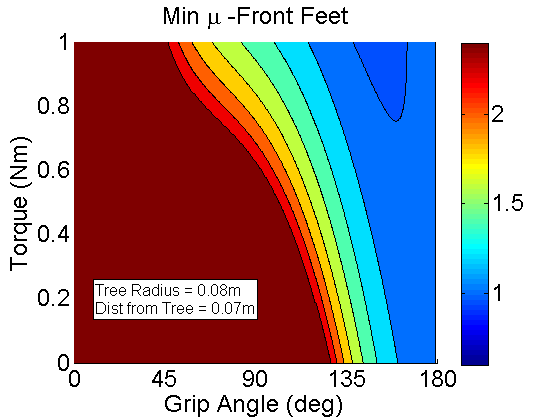
We can start with the simplest case: theta_front = theta_rear and the tail can only exert normal (in the X-direction) forces. This gives us a plot of the minimum mu as a function of the squeeze in force (translated to torque applied at the wing since the longer you reach, the less squeeze in force you have at the contact point) and the angle that you are rotating. The results are shown below. mu=1.2 corresponds to about a cyan color. mu is limited to 2.4 to make the graph easier to read.
This is for the Front feet. Notice that its fairly easy to decrease the needed coefficient of friction by moving the front feet around the tree more. This makes sense since as we are moving around the tree we are using the gravity to help keep us on the tree as opposed to dragging us off the tree.
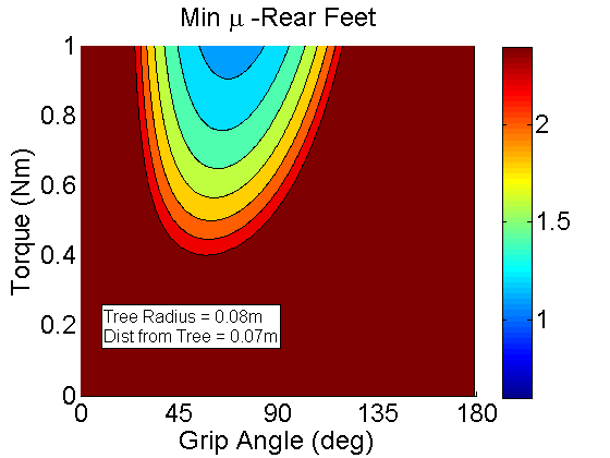
This is for the Rear feet. The results are much different than with the front feet. Here increasing the feet too far around the tree results in a higher mu since you are essentially losing that "jamming." Thus, it is better for the rear feet to stay at the front of the tree.
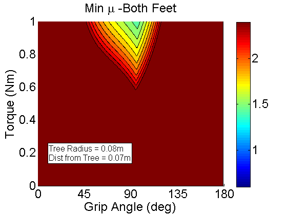
This is for Both feet. Essentially it is the minimum coefficient of friction that is necessary for both front and rear feet to remain stable. Notice that we need to squeeze in a lot and wrap around most of the tree to get reliable climbing. One question to ask is if this is the case, how have we climbed trees before? Two reasons: First we had six legs, and second the large ridges of telephone poles and oak and pine trees effectively make the tree's radius much smaller than it actually is.
QuadraRiSE with the ability to reach around with different angles for its front and rear feet
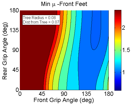
One question that arises from looking at the previous example is how differentiating the angles of the front and rear feet changes the results. These results are plotted a bit differently since we are adding in another variable. We are now plotting mu as a function of the front and rear wrap around angles for a fixed torque. I have looked at what varying the torque does and it changes the results only slightly.For the Front feet.
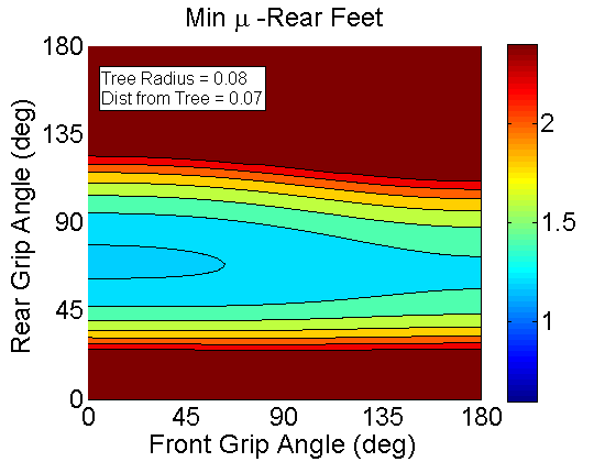
For the Rear feet. At low rear foot wrap angles (less than 30, mu decreases as the front foot angle increases - its just not shown in this graph since mu is limited to 2.4 here.).
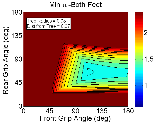
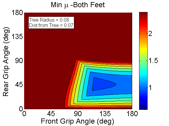
For Both feet. Shows that an optimal foot placement is around 120deg for the front foot and 60 for the rear foot. One question to ask is what the tail is doing in this situation. Is is helping or hurting us? Large animals that climb don't use their tails the way a gecko does. Squirrels don't use their tails for pitch back prevention. In fact the tail might be hurting us since it doesn't let us effectively jam on the wall
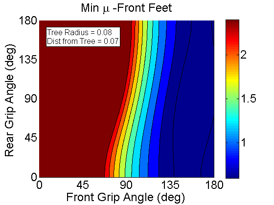
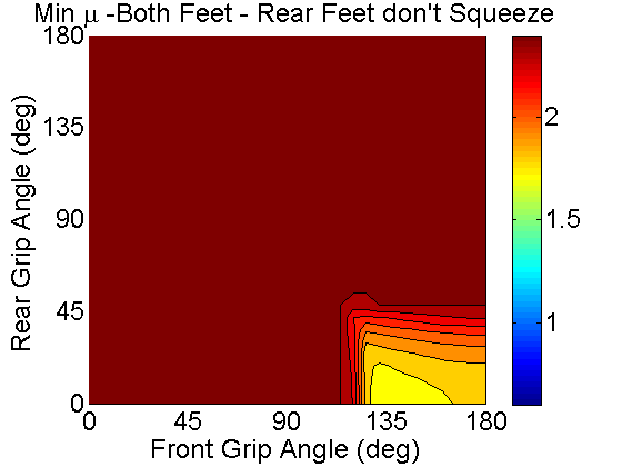
Same analysis with no tail
Let's remove the tail and see if it decreases the required coefficient of friction. Again we're looking at the minimum coefficient of friction for the front, rear, and both sets of feet. Compare the plots to the ones above and you can see that the coefficient of friction does indeed decrease when you lose the tail.
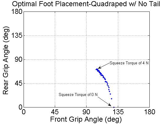
This is what happens if we really differentiate the legs and have the rear legs provide propulsion only:
So the question may be: What is the optimal foot placement for a given robot configuration as a function of the squeeze torque.
The answer is:
When we add in the tail, the points change a bit: Ideas, requests, problems regarding TWiki? Send feedback