new web: http://bdml.stanford.edu/pmwiki
TWiki > Rise Web>ClimbingRobot > ClimbingRobotPeople>SummerUpdates (11 Aug 2006, AmandaValverde? )
Summer Updates: Week 6
Current Work:
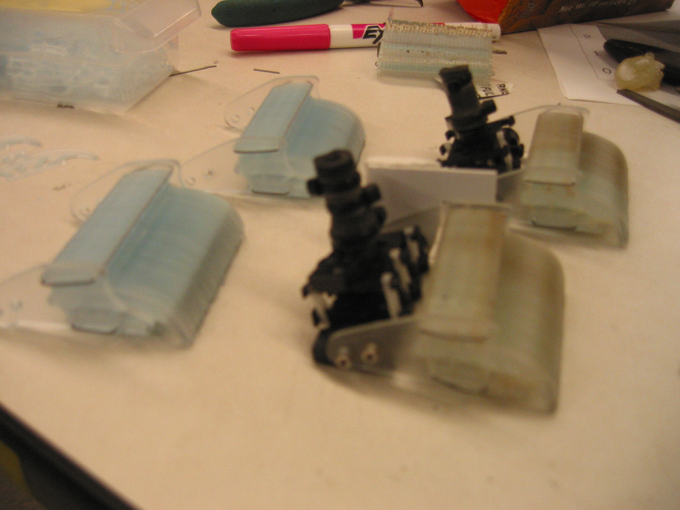
- For now, my main project is making sure that we have enough of the Rise spiny toes to make 10 full feet for Boston Dynamics. As of Thursday, 4 feet have been made with the older, used toes and 2 feet have been made with the new ones.
- The machining process is quite complicated, and requires specific knowledge as each step. Sangbae has helped me through them all, so next week I will be able to finish the last full wax block of toes on my own. The first two full blocks took more than a week to make, having 3 separate toolpaths for each and 2 pourings with the 72-DC and 20-A.
- It looks as if each foot will take 50 toes exactly, so after the 300 needed for the 6 feet, we have 36 left over, 20 of which will go to Derrick who will use them on the new Stickybot design. It will be interesting to see if the design works on both robots.
Projects on the back burner:
- On Tuesday I worked with Seung Bum on developing a new way to cut the stocks on the circular pads. Once he is done with the redesign of the original mold, we should be able to test out the new theory. If it works, then we should be able to add a section of 20-A to the end of the 50-A stocks that will be held in a mold at the correct angle so that nano-tubes can be added later. We are still in the early steps of this process, but it does look promising. For now, the main thing is trying to get in line for the HAAS.
Summer Updates: Week 5
Current Project #1:
- Still in the brainstorming stage for the rotation of Stickybot's feet. I am thinking of adding very low power servos to control the range of motion. For now, I need to focus on the actual movement of the parts during the gait. There is an issue with interference, both with the plastic parts and with having the wires attached to the toes moving unintentionally.
- Matt suggested trying to move the wire bracket to a vertical position above the toes themselves. This would help with the interference with wires, but would most likely require a re-design of the foot/toes. * The main plan for now is to make sure that the wire bracket and the foot itself are connected as one piece, free to rotate around the ankle/arm. If this does not happen, we will have a problem with bending the wires.
Current Project #2:
- The side cases for the new feet for Rise are complete, and all that has to be done is the making of toes, lots of toes. I have started the first batch. They will be ready for pouring tomorrow, and then I will need to imbed the spines, cut again, pour again, and cut the final holes. We will need about 3 full blocks of toes in order to get enough to make a full set of feet to send to Boston Dynamics. For now, the deadline is August 18th, so I will have to keep on it to make sure that they get done in time.
Summer Updates: Week 3
Current Project:
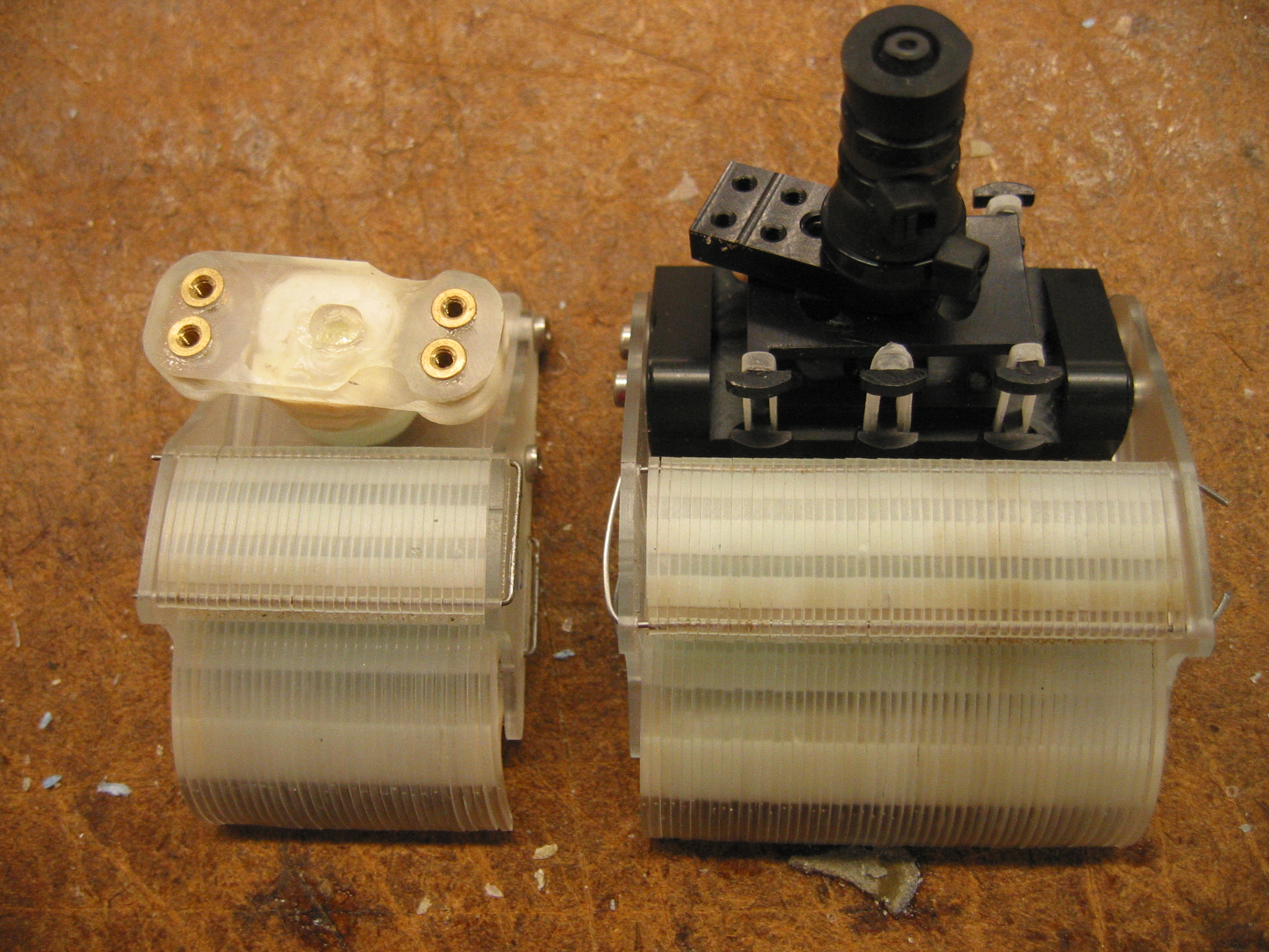
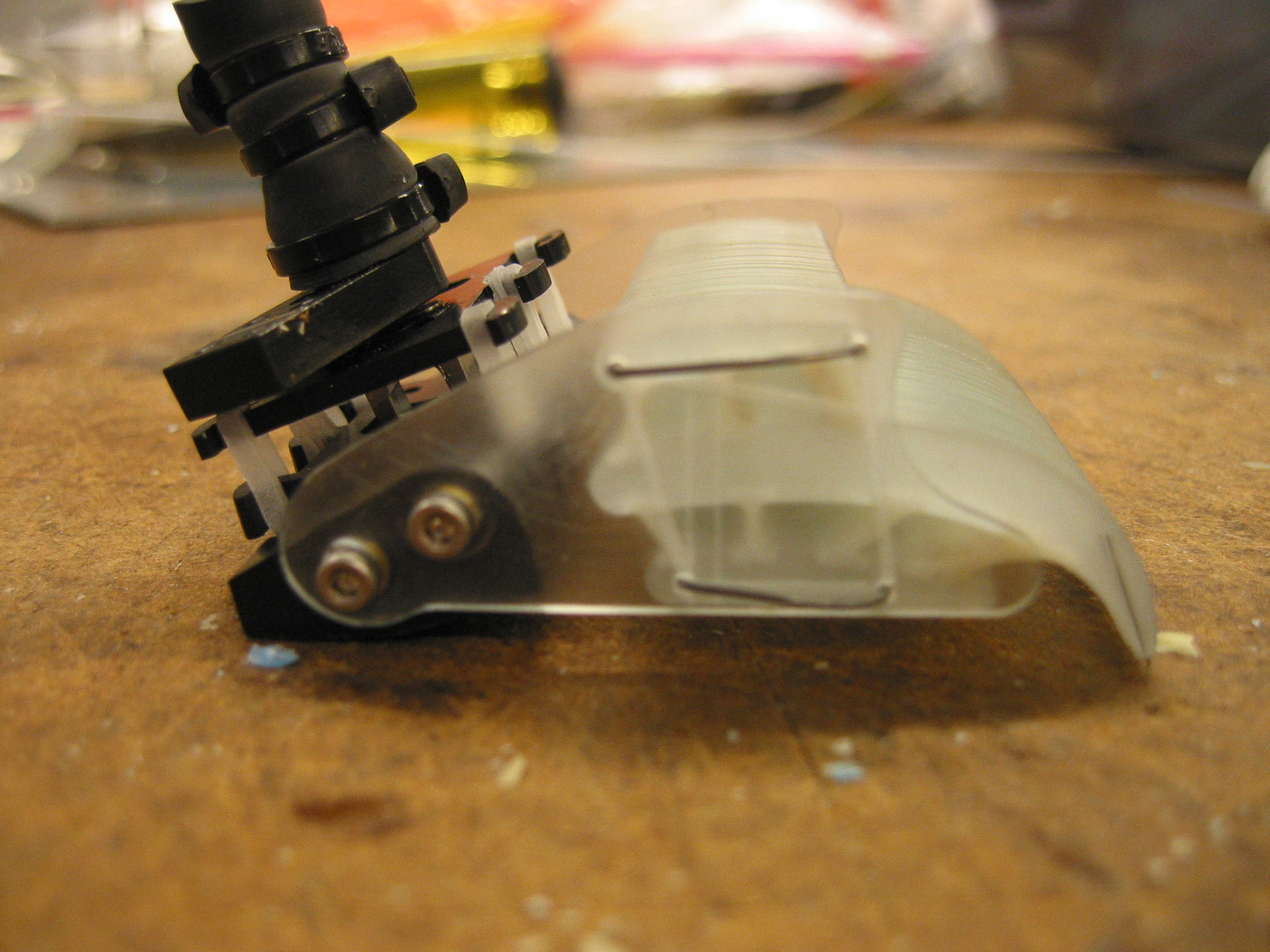
- After having success with the new spiny feet on Rise, we have decided to make a full set of feet in order to test them further. This will mean making enough side casings and toes to outfit at least 10 feet.
- In order to make 10 full feet, I will need to make a whole block of cases and at least 3 blocks of toes. Some of the toes from the older model can be used, but these are only equipped with 30 toes a foot whereas the new feet will require 45-50 toes.
- The toolpath for the toes is already done, by SangBae and today I finished the 1st cut, 2nd cut, and extraction toolpaths for the cases.
- The next step is to SDM all of the parts and assemble. There have been some issues with the curing of the 20-A, so we will have to see how that is going before pouring the softer part of the toes. Also, I need to learn how to form and place the hooks at the end of each toe.
Goals for the weeek:
- Try to finish all parts for new StickyBot. Most of the parts came out in the first block that we made. Some minor glitches in Unigraphics may mean having to do another cut/pour.
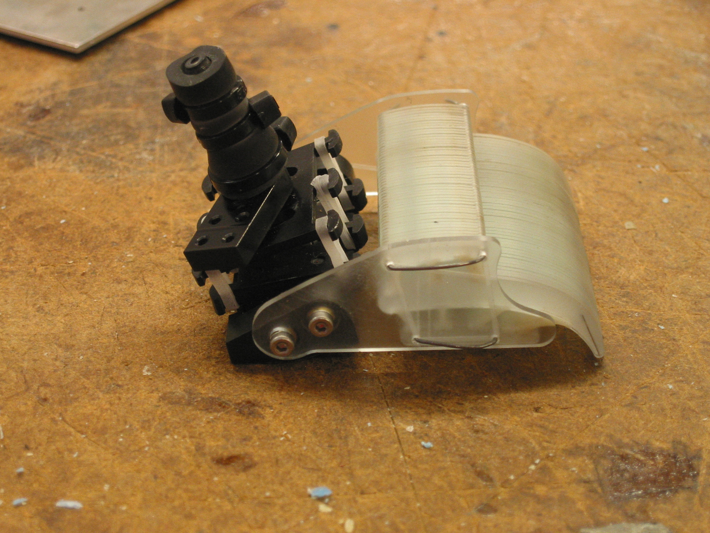
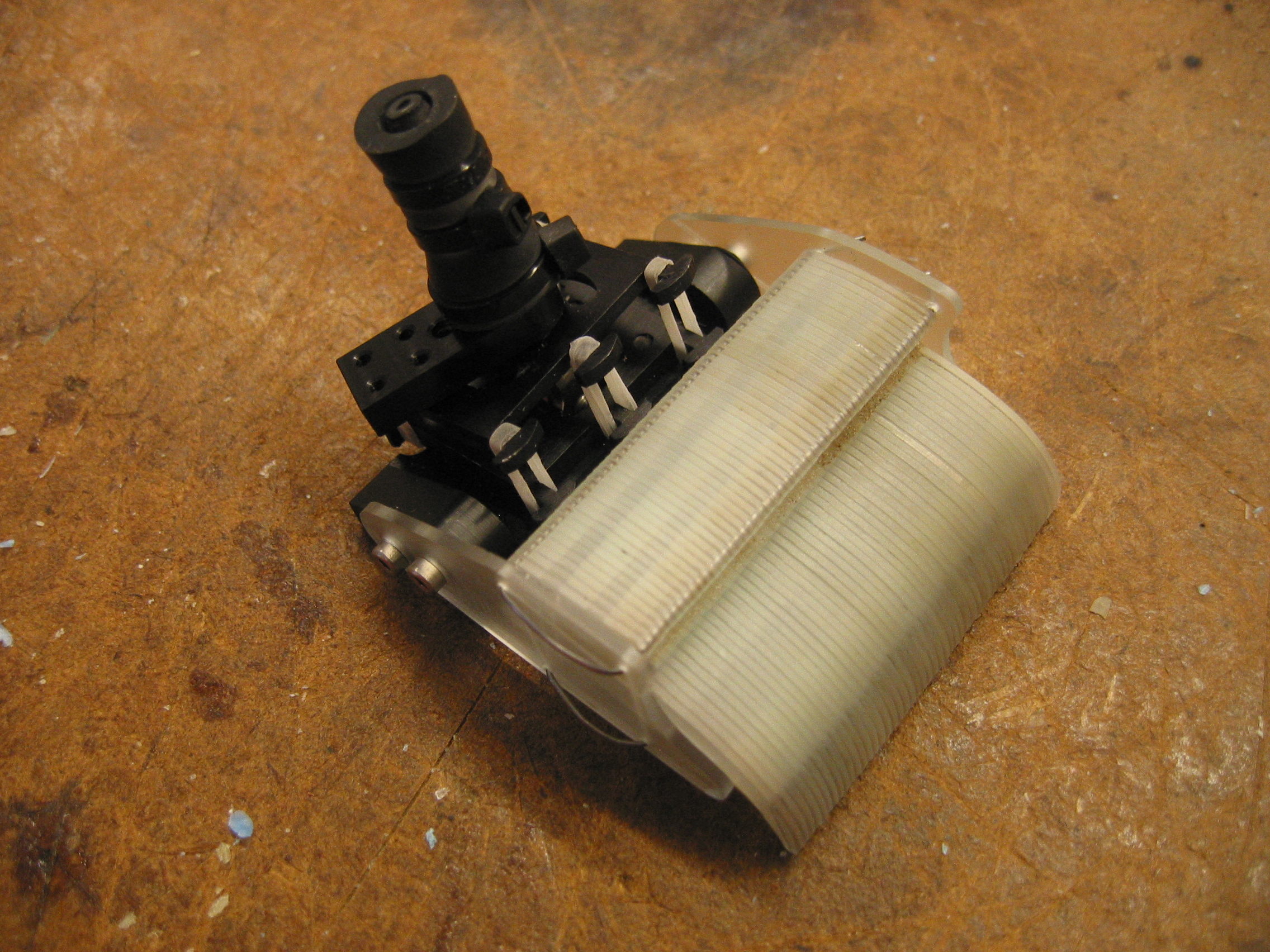
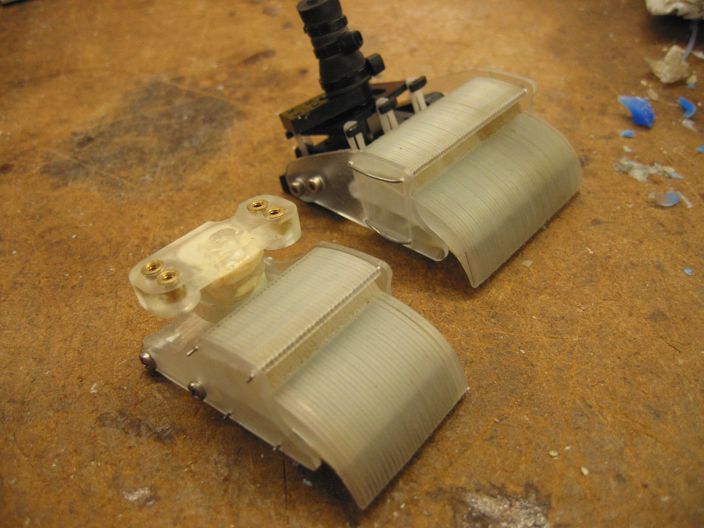
- Finish new Rise feet, using new black ankle from Boston Dynamics and the stretchy toes that Sangbae made. First prototype is done, and seems to work well. The next step will be to make more, so far we only have enough to finish one foot. Also, we want to experiment a little with the angle of the toes. The flexibility seems good, about the same as the current feet on Rise.
Summer Updates: Week 2
SDM Parts for StickyBot- Made a Solid-Works model of the side casing for the new spiny feet on quadrarise. These feet have to able to fit on the Boston Dynamics ankle, so the screw hole positions have to be modified.
- Layed out all necessary parts for a new complete StickyBot body.
- Finished Unigraphics tool path for casings and body.
- Cutting the parts out took about 8-10 hours due to the small tool size and depth of cut.
- Pouring will begin on Thursday, so most of the parts will be done on Friday. There will need to be some secondary cutting and pouring for some of the parts, and those will be done by early next week.
- Need to be able to angle the silicon wafer in a range of degrees (0-60) to provide variability in the exposed light to the SU-8.
- Made a fixture out of an acrylic base. The base needs to be nonreflective in order to minimize the amount of unwanted light coming back onto the wafer. This acrylic base can be covered in another nonreflective material if needed.
- The side posts are 2 copper strips with matching vertical holes in them. A sturdy wire is strung between the two posts to provide the resting platform for the top of the wafer.
- After confirming with Seung Bum, he seems to approve of this first design, but improvements can be made as needed.
Summer Updates: Week 1
Force Sensors
* Working with Sanjay on better way to measure changes in distance/angle between compliant and non-compliant piece in armDesign Ideas
Encoders- Reading changes with encoder that is already there, focusing on getting it attached internally on the arm instead of on the outside.
- This is difficult because of the small scale. Not sure how well this is going to work in the confined space.
- We also have to consider things like wire placement.
- This device would hopefully be small enough to put inside the existing arm, if not some minor design changes would be necessary.
- Would measure changes in angle between the two arm pieces, since it is mounted around the shaft of the servo.
- Parts have been ordered from http://mouser.com. The only one that could be ordered in small quantities was a 15x15x4, which is slightly smaller than the current arm design.
- Once new part arrives, more work will be done on trying to implement new idea.
- Idea from Dan, no one else had really heard of it because it is a relatively new technology. More research needs to be done on this product.
- It is supposed to be very small and capable of very high resolution. Would be great in this application.
- Tried to order a free sample from http://austriamycrosystems.com but their page seems to be broken. Will look for alternative sites and possibly call them to get samples.
Ideas, requests, problems regarding TWiki? Send feedback