Work Log (Weekly Update)
Material toward discussion ( added by Atsuo Orita )
- 19thFeb questions and suggestions ( Attach:toward_discussion.pdf).
- Response from Shiquan: Attach: Answer_Shiquan_Mar4.pdf
- 6thMar questions ( Attach:toward_discussion_Mar6.pdf).
- 7thMar questions ( Attach:toward_discussion_Mar7.pdf).
- Response from Shiquan: Attach: Answer_Shiquan_Mar7.pdf
- 8thMar Opinion for analyzing 5-layer EAP ( Attach:Proposing_Test_Mar8.pdf).
- Response from Mark and Shiquan: Attach: Answer_Mark_Shiquan_Mar8.pdf
On this page... (hide)
- 1. <Jan 16 ~ Jan 29>
- 2. <Jan 30 ~ Feb 5>
- 3. <Feb 6 ~ Feb 12>
- 4. <Feb 13 ~ Feb 19>
- 4.1 Purchase
- 4.2 Testing Apparatus
- 4.3 Material Updates
- 4.4 Fabrication Updates
- 4.5 Etc
- 5. <Feb 20 ~ Feb 26>
- 5.1 Purchase
- 5.2 Fabrication Updates
- 5.3 Test
- 6. <Feb 27 ~ Mar 5>
- 6.1 Material Updates
- 6.2 Fabrication Updates
- 6.3 Test
- 7. <Mar 6 ~ Mar 12>
- 7.1 Test
- 7.2 Material Updates
- 7.3 Etc
- 7.4 Test
1. <Jan 16 ~ Jan 29>
- Initial research (Attach:Report_Jan.pdf).
2. <Jan 30 ~ Feb 5>
- Purchased things for cured carbon-silicone electrode coating (Attach: Purchase list_1.pdf).
- Finished learning current fabrication method, many thanks to HannahStuart ! See the results in: Attach: Photo_EAPs.png.
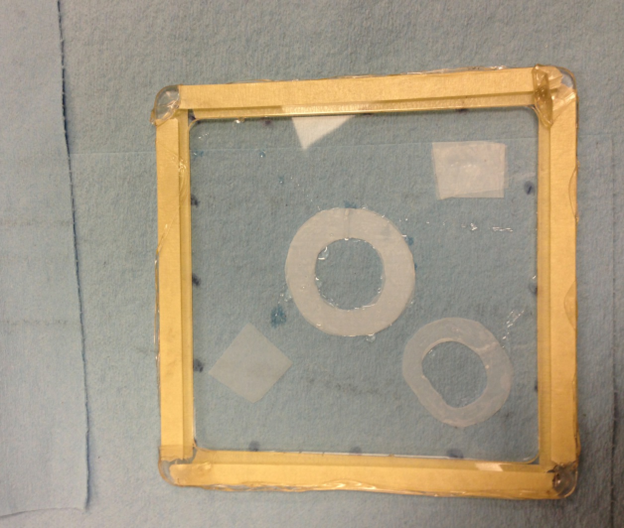
- Frame for cured electrode trial (Attach: Photo_Frame with acrylic film.png)
- No sharp edge so the stretched film could stay on it without tearing (electrode needs one hour to cure but current fiber glass frame cannot guarantee). Keep the film stretched without tape or glue.
- Tested with stretched film without tearing for more than four days.
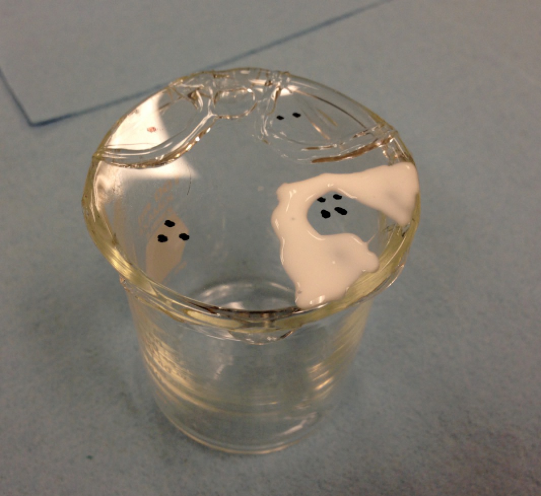
- Glue test
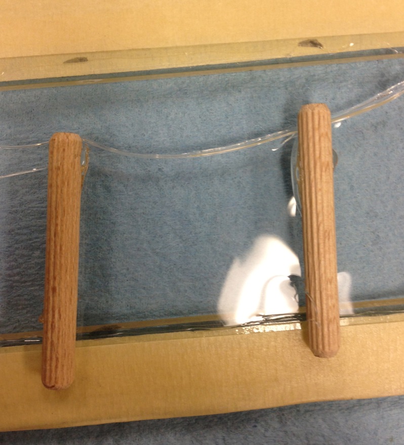
- Consider using wood downpin as the pillar for rotary suspension design.
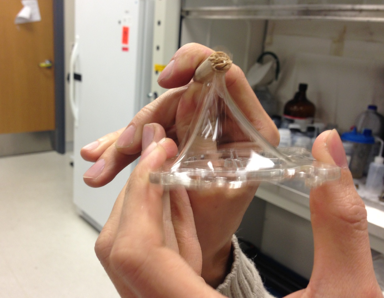
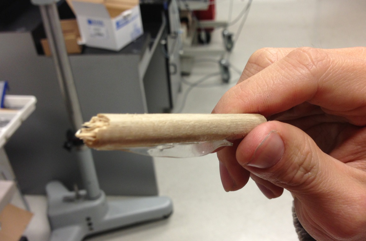
- Found a glue that works well. See the test in: Attach: Photo_Glue test.png. The bonding stayed intact after the acrylic film was torn (Attach: Photo_Torn film.png).
3. <Feb 6 ~ Feb 12>
- Brief EAP hysteresis introduction for Atsuo: Attach: Hysteresis_Feb11.pdf.
- Finished learning Muscle Lever 305B for experiment. Thank you AliceWu!
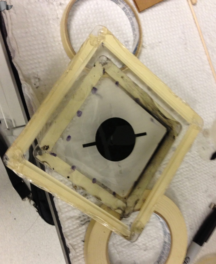
- First trial of cured electrode (photo: Attach: Photo_Cured electrode.png)
- Smooth-on Max-mold 10T hasn't come yet, try with dragon skin (same durometer but twice elongation capacity).
- The cured surface is quite even with proper spraying. Don't spray too closely and always make sure the airbrush is pressed properly (with lightly pressing, air will come along with the mixture and create bubble on the film, Attach: Photo_Electrode with bubbles.png).
- DIfficult to control the electrode thickness when spraying. Can only judge from the opaqueness and clots on the film.
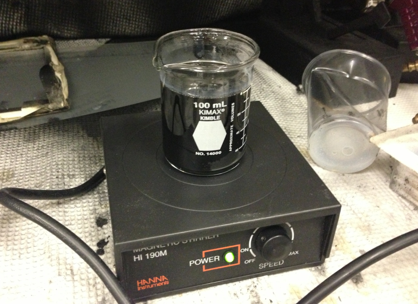
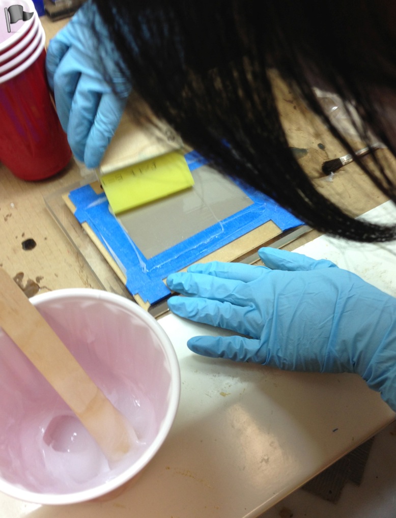
- Using magnetic stirrer for the mixture, need to manually stir first so as to reduce the viscosity of the bottom mixture and make the mini stir bar freely spin (Attach: Photo_Making mixture.png).
- The mixture adheres strongly to the acrylic film: immediately form an opaque layer by spraying (2 second) and need around 20g mixture for one batch (It takes few minutes for carbon grease method and waste a lot of chemical).
- Actually, it cures super fast within 15 minutes.
- Electrode cured well on both masking and acrylic film, difficult to find a warp corner of the masking to peel it off.
4. <Feb 13 ~ Feb 19>
4.1 Purchase
- New purchase (Attach: Purchase list_2.pdf).
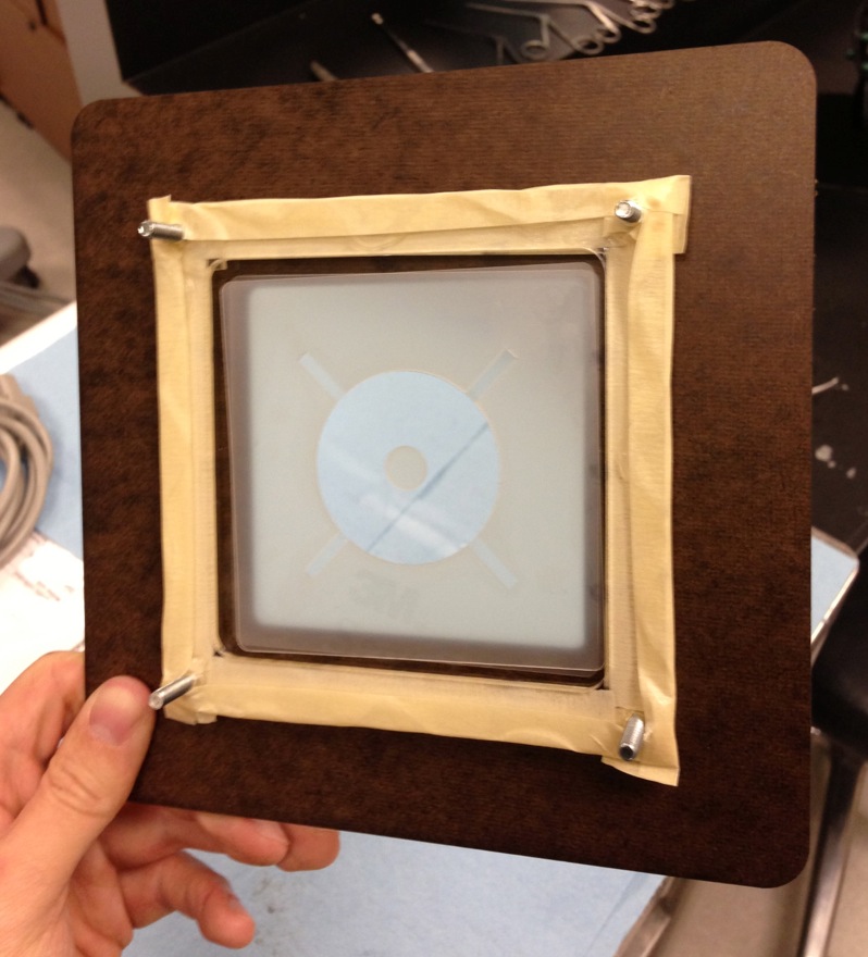
4.2 Testing Apparatus
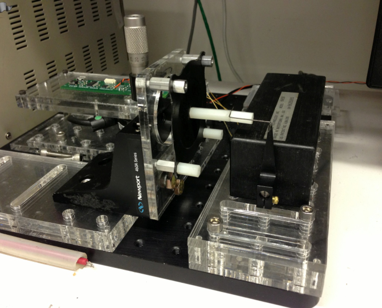
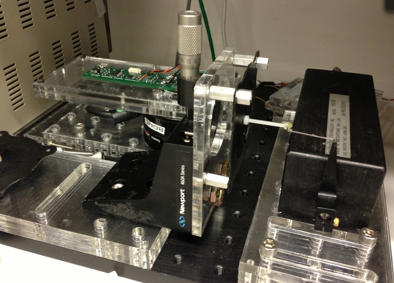
- Set up a new test platform: Attach:Photo_basic test platform.png.
- lever movement and diaphragm center should be strictly coaxial.
4.3 Material Updates
- Unified frame, easy replacement of suspension units for tests. Planed tests include: 1) suspension with carbon grease electrode. 2) cured electrode made by different methods (dragon skin vs. Mold-max 10, hexane vs. toluene). 3) multiple layer
4.4 Fabrication Updates
- Improved the fabrication method, designed rapid multi-layer fabrication procedures and needed parts and tools (Detailed description will be provided after first trial).
- Glue test: stainless dowel pin bonds well with acrylic film. Acrylic film coated with cured electrode cannot bond with wooden or stainless dowel pin. So where the pillar adhered on the film should not be coated with electrode.
4.5 Etc
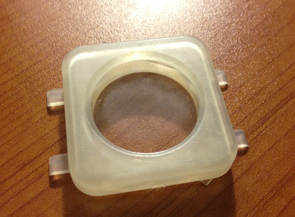
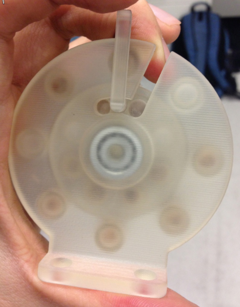
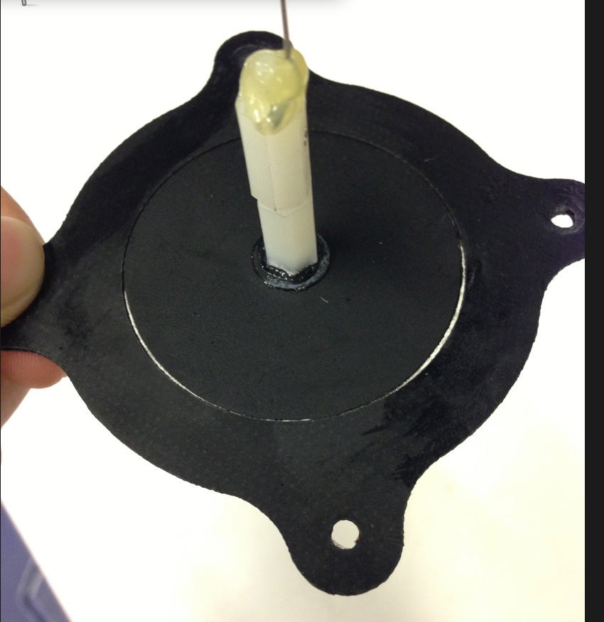
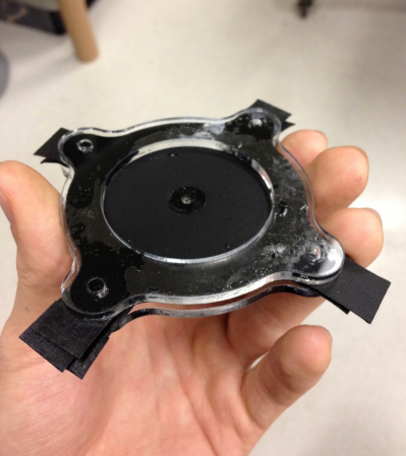
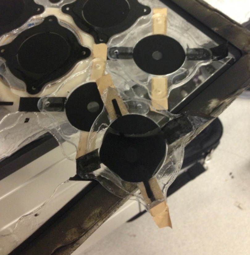
- Rotary suspension design conceptual prototype: Attach:Photo_primitive rotary suspension.png
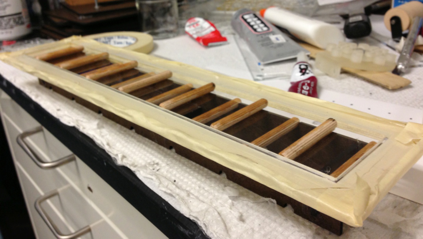
- Procedure: stretching film -> gluing pillars on both sides using extra frame (Attach:Photo_pillar sticking.png) -> cutting acrylic film with pillars out from the stretching frame -> installing onto the turnplate.
- Finding:
- The length of stretching frame is too long compared with the width, which increases the failure rate.
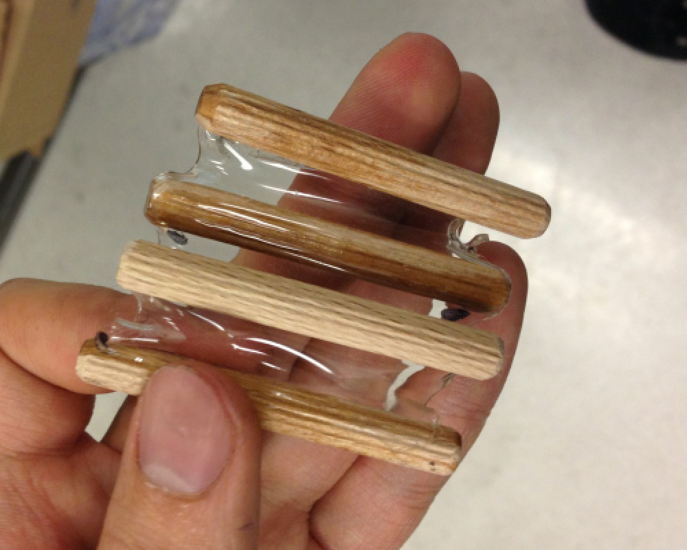
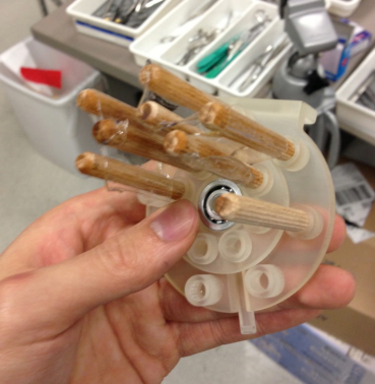
- With shrinking film between adhered pillars(Attach:Photo_adhered pillars with shrinked film.png), it is very easy to install the pillars onto the plate by stretching the film. Considering pre-stretching the film by only 200% for reducing the length, further stretching it to 300% when installing the pillars(Attach:Photo_plate with installed pillars.png).
- The dowel pin doesn't fit well with the holders on the plate and cannot ensure perfect vertical. Friction exists when rotating the plate. Related mechanism need to be improved.
- Stress concentration at interface between pillars and film. Better to use thick and flexible adhesive rather than thin glue to attach the pillars.
- Tearing is easily generated and propagated from the edge especially when cutting the film out from the stretching frame. Necessary to create an anti-tearing boarder on the film to prevent the tearing propagation, otherwise the current rotary suspension design is not feasible.
- Anti-earing boarder tests: exploring ways to prevent potential tear propagation from edge for planar configuration.
- The boarder should: 1) be flexible and low stiffness. 2) bond strongly with acrylic film so as to block the tearing propagation. 3) not cure immediately but quickly enough.
- Coated with dragon skin doesn't work: dragon skin cannot strongly bond to acrylic film, separated from the film when tear is propagating.
- Glue tests (Attach:Photo_anti-tearing glue tests.png)
- E6000: works best, but still not perfectly soft enough. Able to block the tearing propagation.
- IPS WELDON #16: too stiff, long curing time.
- ELMER's GLUE-ALL: too stiff.
- Other possible solutions: urethane rubber coating, other flexible adhesives.
5. <Feb 20 ~ Feb 26>
5.1 Purchase
- Purchase: Attach:Purchase list_3.pdf
- Anti-tearing boarder
- E6000: Attach:Photo_E6000 anti-tearing border.png
- Compare with different options include: epoxy polymer adhesives, methacrylate adhesives, urethane adhesives, polysulfide rubber. Candidate: DP105 3M� Scotch-Weld� Epoxy Adhesive (500 psi modulus, 250psi shear bonding strength to acrylic)
5.2 Fabrication Updates
- Tried with other options (hexane and MoldMax 10T) for cured electrode
- Worked much poorer than combination of toluene and dragon skin: difficult to adhere on acrylic film and takes much longer time to finish the spray.
- Probably because of less viscosity of hexane and longer cure time of MoldMax 10T.
- Should keep the mixture stirred until no whirlpool appears.
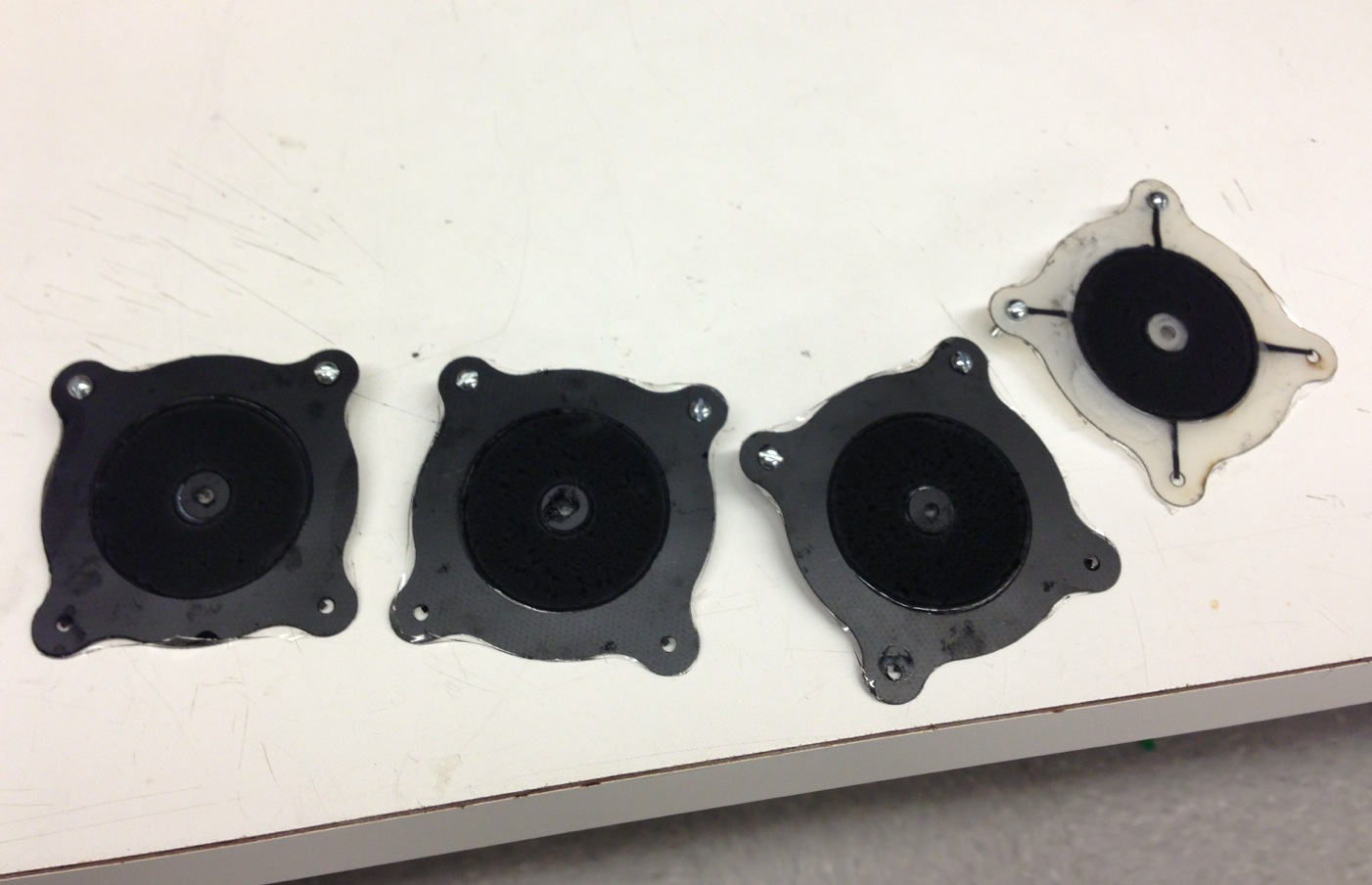
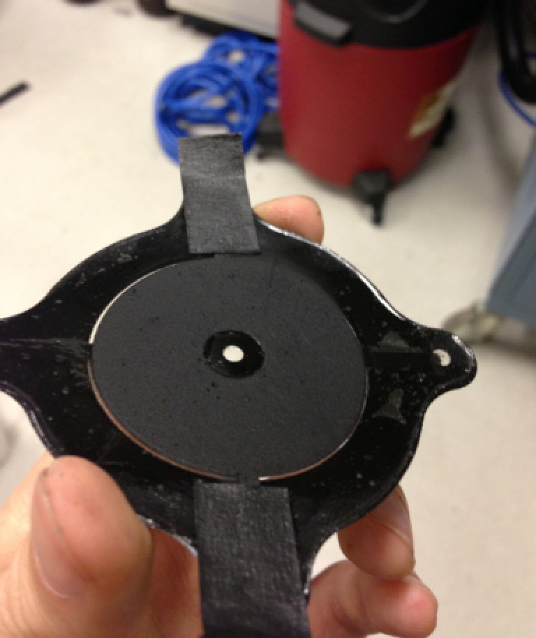
- Multiple layer: able to make a 3-layer suspension (Attach:Photo_3-layer suspension.png).
- Basic procedure: stretch acrylic film on the small stretching frame -> put electrode masking on both side and keep the bottom side fully covered-> install the stretching frame onto masking frame to keep it clean (Attach:Photo_masking frame.png) -> spray on the top side and peel of the electrode masking -> stretch acrylic film on the large stretching frame and overlie it on the small one with sprayed electrode (Attach:Photo_stretching film overlying.png) -> cut the film from the larger frame and wrap it on the small one without slipping (critical)-> clean the large frame and put on another stretched film -> spray on the new layers with electrode masking on it-> repeat adding layers using the same way -> spray the bottom side
- Finding:
- The current fiberglass outer frame is not strong enough to hold the 3-layer suspension.
- The masking frame cannot fully prevent the stretching frame from electrode spray. Need to be larger and stay closer to the stretching frame.
- Super glue cannot do any good to prevent the slippage when cutting off the larger film. Solely wrapping is enough but the large stretching frame need to be larger to provide wider film edge for wrapping.
- Painful to alternately work on stretching film and spraying because the carbon mixture is quite messy...
- With current method, marginal time cost for adding one layer is around 20 min.
- Consider new method to accelerate the process: glue super thin rigid film as the outer frame on only one side of the acrylic film (or two sides if it curl) so as to produce layers in batch, then attach them together. Candidate material: 0.002" PTFE sheet. This method is not helpful for large film fabrication.
5.3 Test
- Reduced the mass between suspension and the lever to address the resonance of the muscle lever (length control): Attach:Photo_mass reduced.png
- Test without actuating:
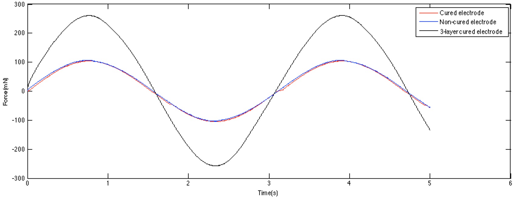
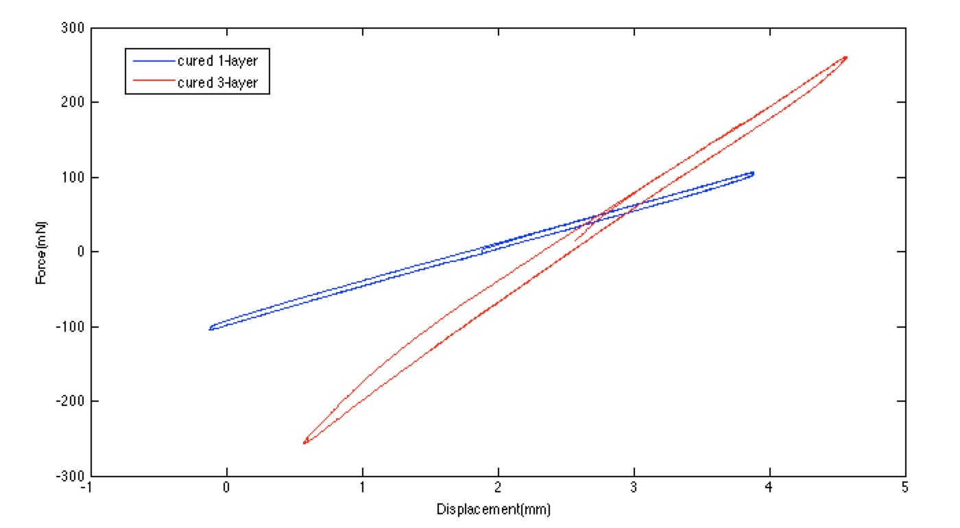
- Experiment data plot: 1) Attach:Plot_force vs. time_Feb25.png 2) Attach:Plot_force vs. displacement_Feb25.png
- Cured electrode doesn't add any stiffness to the suspension. Probably because the electrode is already in slack condition when cured.
- 3-layer suspension average stiffness is 2.5 times than single layer but not 3. Probably due to the compliance of the fiberglass outer frame and only 4 layers of electrodes.
- Actuating test:
- Haven't come across any short so far which indicates good stability of cured electrode.
- Connection problem: purely electrode antenna cannot ensure reliable connection between electrode and metal screws on the outer frame. Consider carbon grease+metal conductive tape which is used in Sanjay's work. But need to find a flexible, softer and thiner conductive tape for multiple layer suspension.
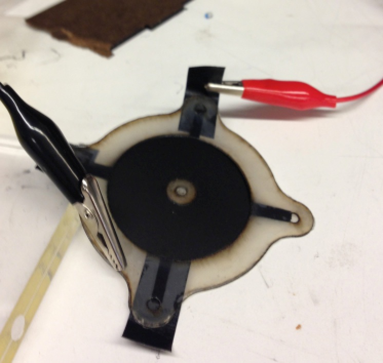
- Despite of the connection problem, directly lay high voltage supplier cable pins on both sides of the suspension can successfully actuate both single and 3-layer units stably.
6. <Feb 27 ~ Mar 5>
6.1 Material Updates
- Try with PTFE 0.002" sheet: Attach:Photo_PTFE_trial.png
- Can adhere with acrylic film very well without any glue.
- The stretch of acrylic film can be maintained by covering both side with this sheet, doesn't need glue and also easy to peel off. Can be a good way for stretched acrylic film manipulation.
6.2 Fabrication Updates
- Multi-layer fabrication investigation
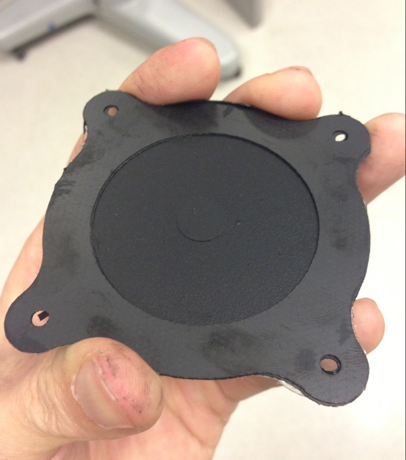
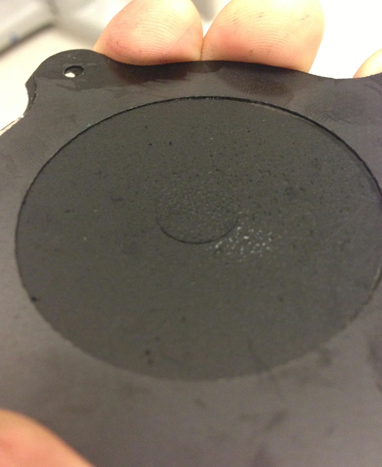
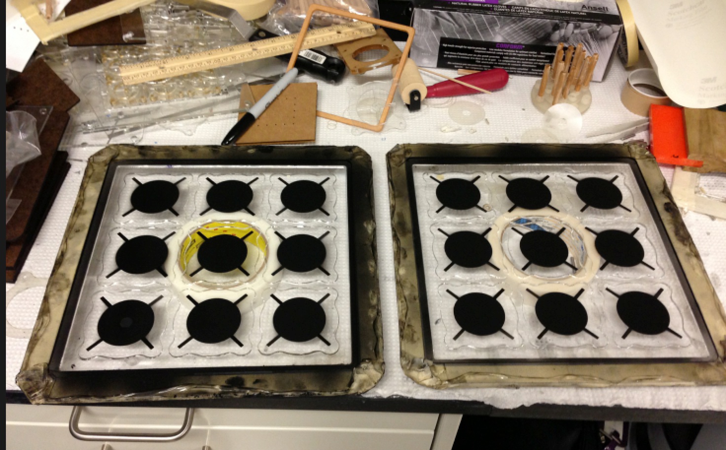
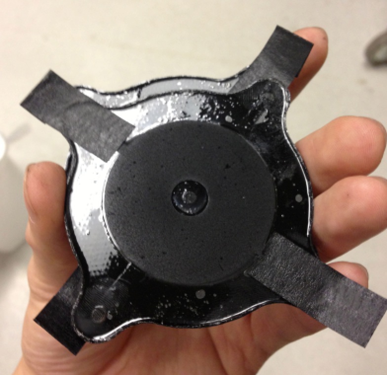
- Result: made a 5-layer EAP (Attach:Photo_5layer_EAP.png) by trying two different ways of fabrication in batch (Attach:Photo_fabrication_in_batch.png) and deal with the connection problem.
- First method: using transferring frame to separate the acrylic film into independent areas for ceasing the tearing propagation (Attach:Photo_transferring frame.png). Glue the base on one cell, cut it off, glue on another one, so as to increase the layers on the base.
- The base is made from one eighth acrylic plate, difficult to have all continuous edges glued on the film. Glue problem also occurred between two acrylic layers (Attach:Photo_layers_adhereing_failure.png).
- One solution might be finding a better glue which: 1) very thin; 2) quickly dry within 10 minutes; 3) doesn't need air to cure.
- Considering contact adhesive.
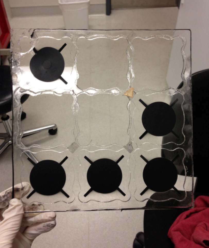
- Second method: glue thin supporting frames to each layer just on one side, cut them off as units and pile them up with glue (Attach:Photo_piling_units.png).
- A supporting frame with flexibility (0.01'' fiberglass currently, could be even thinner) can be much better and more easily glue on the acrylic film than rigid acrylic plate.
- After cutting the cells out, the acrylic film edges warp and curl little bit (Attach:Photo_cell_edge_curl.png), which will increase the overall thickness when these cells are piled up. Need to find ways to prevent it.
- Electrical connection: (Attach:Photo_electrical_connection.png)
- Conductive tape should be thin and flexible, not easy to wrinkle.
- The thickness of tape is bad for evenly touching and gluing between two layers, better to extend the electrode line and put the conductive tape outside the frame.
6.3 Test
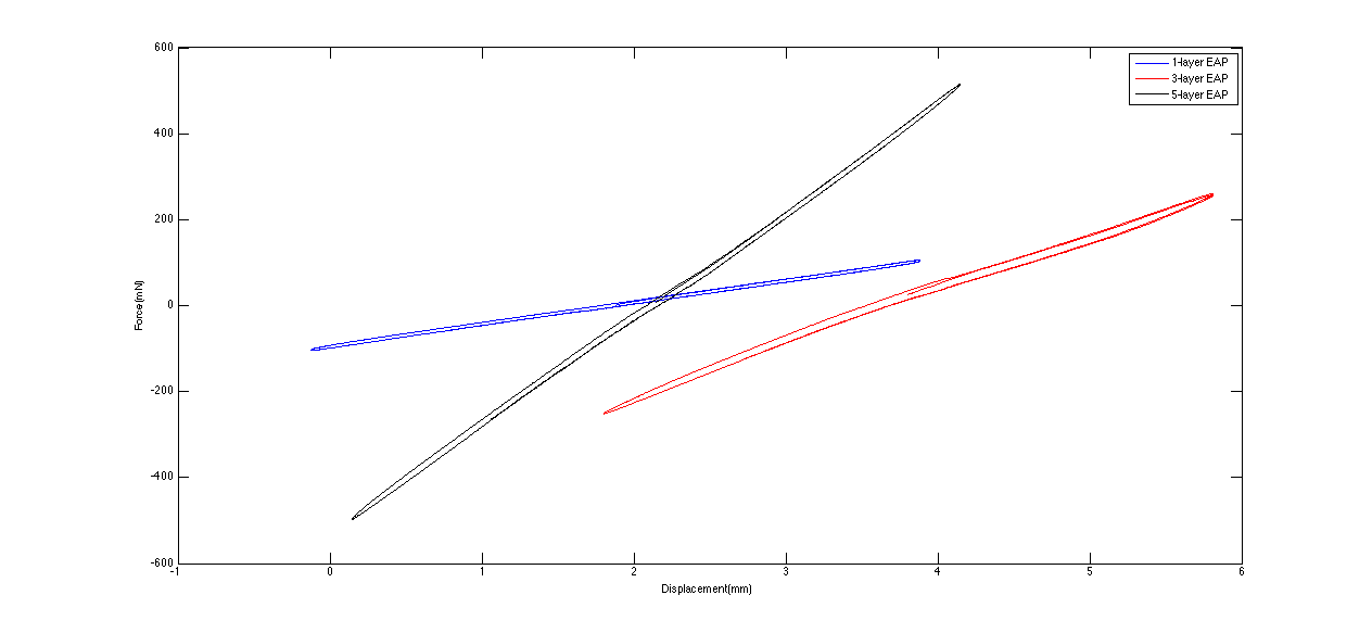
- Hysteresis and stiffness of 1, 3, 5-layer EAP (supporting frame of 3-layer one has been strengthen): Attach:Plot_hysteresis_and_stiffness_0.4Hz_2Amp.png
- The hysteresis doesn't actually scale up with the increase of layer number.
- Need to mention, each layer in 3-layer EAP has only one side electrode while 1 and 5-layer have two-sided electrode.
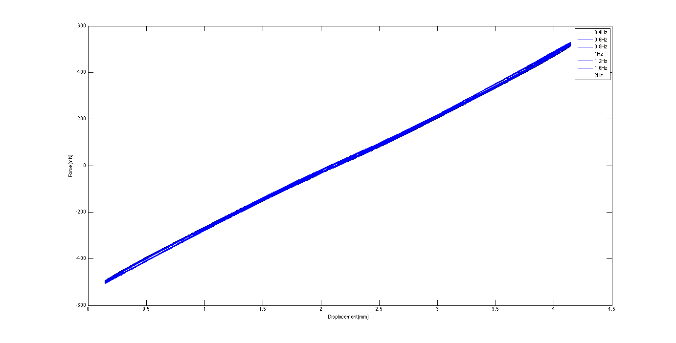
- Hysteresis of 5-layer EAP under different frequencies: Attach:Plot_hysteresis_different_frequencies.png
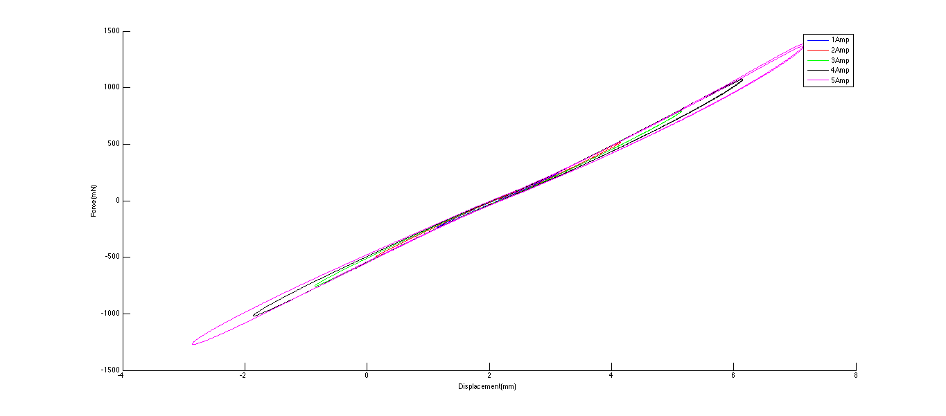
- Hysteresis of 5-layer EAP under different amplitudes: Attach:Plot_hysteresis_different_amplitudes.png
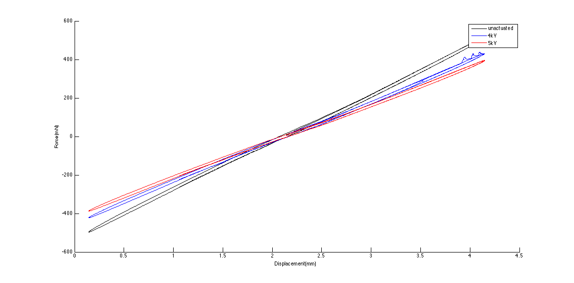
- Actuated 5-layer EAP: Attach:Plot_actuated_tests_Mar5.png
- The stiffness range is small, which is because of: 1) one of the layer doesn't work because of lack of conductive tape. 2) no electrical connection strengthen between two adjacent layers. 3) short occurred because of acrylic sheet contamination during fabrication and cannot actually generate the input voltage (the plot legend is for input voltage, not actual value). 4) More reasons?
- Hysteresis and stiffness of 1, 3, 5-layer EAP (supporting frame of 3-layer one has been strengthen): Attach:Plot_hysteresis_and_stiffness_0.4Hz_2Amp.png
7. <Mar 6 ~ Mar 12>
7.1 Test
- Found reasons for actuation problem of 5-layer EAP
- Each layer has only one fiberglass frame on one side and warp a bit. When one layer (without piling up), the warp recovered obviously, which means the actuation of single cured layer is good.
- Key problem: the fiberglass used in this prototype has burnt edges which might contain or be sticked with some carbons and short the entire frame (Attach:Photo_shorting_frame_edge.png). Since in the 5-layer prototype, all the conductive tape is contacting the frame edge, it is impossible to fully charge it without shorting.
- Notice that it is easy for cured electrode to have electric connection failure. So for next prototype, both sides of EAP should be directly connected with conductive tape.
7.2 Material Updates
- Finding replacement of fiberglass for multiple layer frame
- Reasons: 1) prevent burnt edge shorting 2) thinner and smoother on the surface and edge
- Requirement: 1) thin (not thicker than 0.01") 2) easy to adhere on acrylic film (would be great if no glue is needed) 3) good electric insulation. 4) easy to be laser cut without being burnt
- Current candidates: 1) Easy-to-Machine Impact-Resistant ABS 2) Wear-Resistant Nylon 3) Wear- and Water-Resistant Delrin� Acetal Resin (link for these materials)
7.3 Etc
- glue test for anti-tearing-propagation borders DP105 3M� Scotch-Weld� Epoxy Adhesive
- Super flexible and bonds strongly with acrylic film (dragon skin can't).
- Cured within 15 min and thin enough to manipulate.
- Good choice for rapid fabrication of anti-tearing-propagation border.
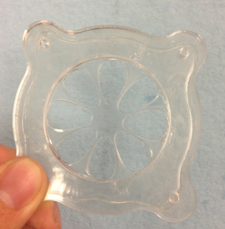
- Managed to laser cut stretched acrylic film and made a funny prototype : Attach:Photo_flower_film_unit.png
- 0.002" PTFE sheet and 0.01" fiberglass transferring frame
- Laser cut setting: speed 90%, power 40%, frequency 500Hz.
- Procedures: Attach:Procedure_laser_cut_stretched_flim.pdf
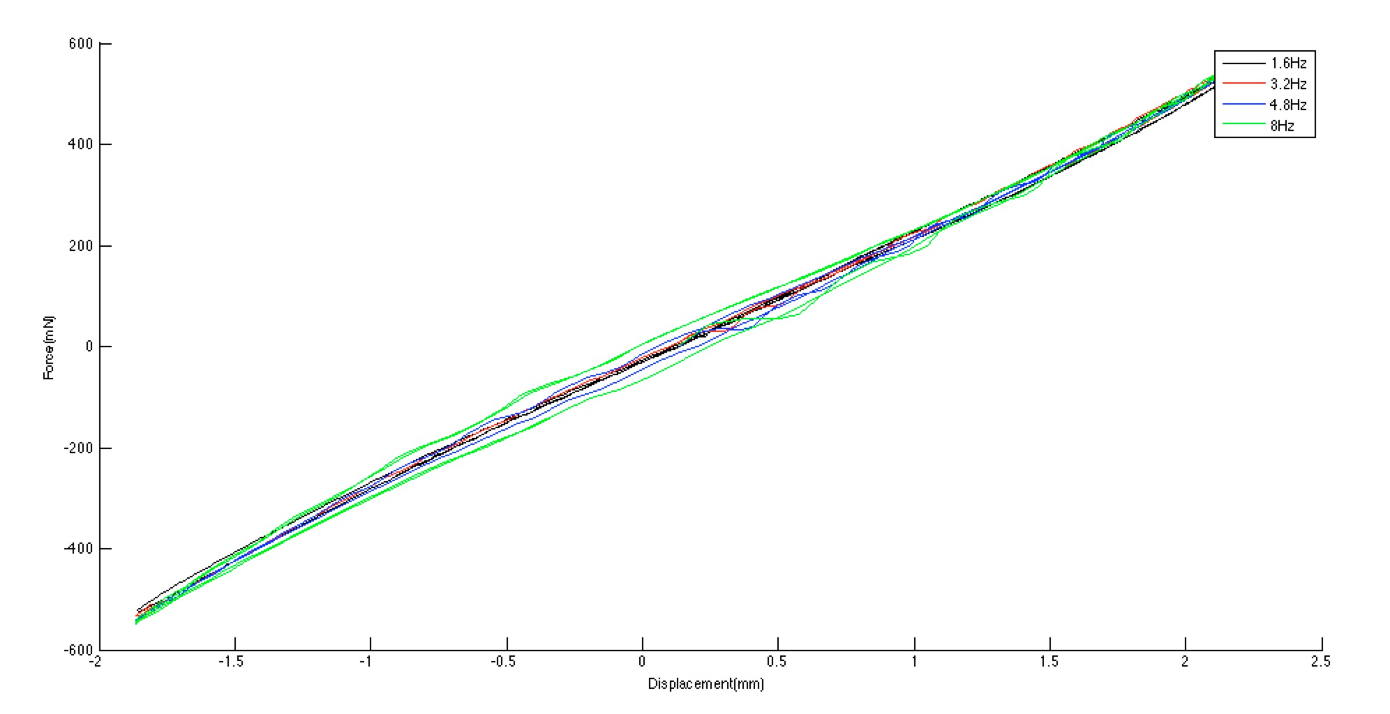
- Retested 5-layer EAP with higher frequencies: Attach:Plot_5layer_higher_frequencies.png
- Observed oscillation when frequencies were too high, reaching the control limit of muscle lever.
- Is the process of fabricating 0.005" silicone film Alice use can be applied for EAP electrode fabrication?
- use thin film as mold and pressed by acrylic plate (glass might be better) and some ballasts: Attach:thin_film_molding_Alice.png
- spraying method is the key reason that makes things messy when making EAP.
7.4 Test
- System Identification
- All the data was filtered by 0-1000 rad/s.
- Tried different number of pols and zeros for model fitting: Attach:Plot_zeros_poles_fitting.pdf
- Turned out 1 zero 1 pole system worked best. (Tested under 0.4 and 4Hz)
- Increase the poles and zeros cannot necessarily improve the fitting accuracy.
- All the analysis below are using 1 zero 1 pole model.
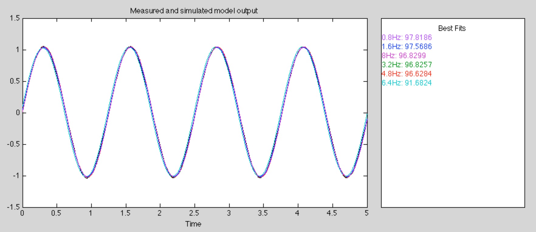
- 5-layer data under different frequencies: Attach: Plot_different_frequencies.png
- Use the 0.8Hz data as validation data to evaluate coefficients got from 0.8Hz ~ 6.4 Hz data. Fitting rates are all above 0.9.
- 1,3,5-layer data under different amplitudes: Attach: Plot_135layer_different_amp.pdf
- Fitting models are different for different layers
- Single model can describe the EAP under different amplitudes with fitting rates above 0.9.
- Spring and damping calculation of estimated models for different layers EAPs under different Amplitudes: Attach: Calculation_spring_damping.pdf
- Damping ratio doesn't show a trend of increase as the layer number increases (but the sample might not be large enough).
- The damping ratios are quite stable among those 4 out of 5 cases (same layer number, different amplitude).
Page last modified on June 02, 2013, at 12:28 pm