Profiles.VanessaIbarra, SummerBlogs
Vanessa's Summer 2016 Blog
Week Nine
9.3 Thursday, August 18
9.2 Wednesday, August 17
9.1 Tuesday, August 16
Week Eight
8.3 Thursday, August 11
8.2 Wednesday, August 10
8.2 Tuesday, August 9
8.1 Monday, August 8
I started off today by catching up a little on my blog in the morning. I will be presenting the work I've done this summer to Dr. Noe Lozano and the rest of the SURF program this Thursday so I spent the rest of the morning working on my presentation.
I had spoken to Hannah about the issues I had been having with the large vibrations and forces during the rubber skins experiment. Both centrifugal pumps were also not working as usual and I couldn't figure out why. I suspect one is damaged from the sand, but the other will just freeze and not allow any flow through it. She suggested doing two things: 1) Turning off the pump when the force on the ATI Nano was high and continuing to lower the fingertip a few steps. Then turning on the pump again to see if I had been able to skip the range where the force peaked right before the fingertip makes contact and 2) Starting off with the positive displacement pump and splitting the tube to have less flow/force at the fingertip. In the afternoon, I set up the tank and pump to run these experiments.
Week Seven
7.5 Friday, August 5
This morning's lab meeting consisted of Mark talking about his experience at the conference abroad and going over the goals the lab had set for August at the retreat. I found that I have learned a lot of what I wanted to get out of this research experience. I got a lot of experience using SolidWorks, I'm no professional but I am really comfortable using the interface. I've gone through a lot of the design process, I worked on soldiworks, laser cut parts, built the setup, then started using it for experimental trials. I'm currently stuck in the scientific method, and I'm learning a lot about how to approach problems and analyze the results in a way that helps guide us towards the next step in the process. I'm also learning a lot from Hannah in interpreting results in a meaningful way and tailoring the experiments to look for an interesting or significant trend or result. Although our progress for the ICRA paper was slower than expected due to some bumps and wrong turns, I think we have enough time to finish. I am going to do as much as I can these next few weeks to meet our goal.
After the MERL BBQ I processed the data from yesterday in matlab. These were my results:

This was a good place to end the week, next week I will go back to studying the different rubber skins on the fingertip.
7.4 Thursday, August 4
This morning I processed the data I took yesterday in Matlab. I wrote a new script that plotted pressure vs flow rate and pump efficiency vs pressure. Hannah got back today so we met to go over the data I had gathered this past week. We discussed how the plots I had didn't reflect the same results that we had seen earlier in the summer. After a closer look at the setup we realized that I had incorrectly measured pressure. I used the differential pressure lines attached to the neck and used the data from the pressure transducer as pressure data when in reality this was measuring flow. Therefore one of my plots was actually flow vs flow and the other was pump efficiency vs flow. I also wasn't sure how the sand in my experiment had affected the data because I couldn't control that throughout the experiment. Throughout the different trials the fingertip could have come in more or less contact with the sand causing different trials to clog or the pump to take in more sand, not only because of the mesh but because of the amount of sand available. I decided it wasn't something we could standardize so I also wanted to redo the experiment with clean water.
I went back to the lab and changed my set up to have one pressure line at the input of the pump and the other at the output. I cleaned out the water in the tank which had unfortunately gotten sand in it when the beakers tipped over a few times yesterday. I reduced the length of the tube connected to the fingertip to reduce headloss by making the tank the source of clean incoming water and just having a longer output tube to fill a beaker. The correct set up is shown below:

I returned to the lab after dinner to redo the experiment for both pumps. To reiterate I took the centrifugal and positive displacement pumps and measured the flow, pressure, average voltage and current with varying meshes on the fingertips. I made sure to use the two pumps that had not been used with sand.
7.3 Wednesday, August 3
Today I set up the experiment to take data. I will have the pump suck in a water/sand mixture through the fingertip and output it into a second beaker, simultaneously measuring the flow by timing the how long it takes to fill up the second beaker up to a certain volume. In addition I would be measuring the pressure of the pump and looking at the power source and documenting an estimate of the average voltage and current.

I ran the experiment starting off with the smallest mesh that would allow the least amount of sand to go through in order to avoid starting off with a lot of sand getting in the pump and damaging it. The order was mesh 50, 30, 24, 20, 8, and no mesh. I did this for both pumps, allowing the pump to cool down for a few minutes and running clean water through the pump between trials. I found that it was difficult to measure the no mesh trial because the suction force would cause the tube to close up.
7.2 Tuesday, August 2
The different sized meshes arrived today right before lunchtime. I took a part of the mesh-20 and placed it over a beaker. I then took some of the sand and poured it over the mesh. I repeated this for the remaining 24, 30, 50, and 60 meshes. I noticed that there was very little difference in what sand was able to get through the holes of the mesh 50 and mesh 60, so I decided that for the experiments I would only use up to the mesh-50. I also decided to measure the size of a mesh that Will had given me and Hannah. It was a size mesh 8, meaning the holes were quite large and I thought this would be a good extreme point where most of the sand would go through and there would be a large flow area.
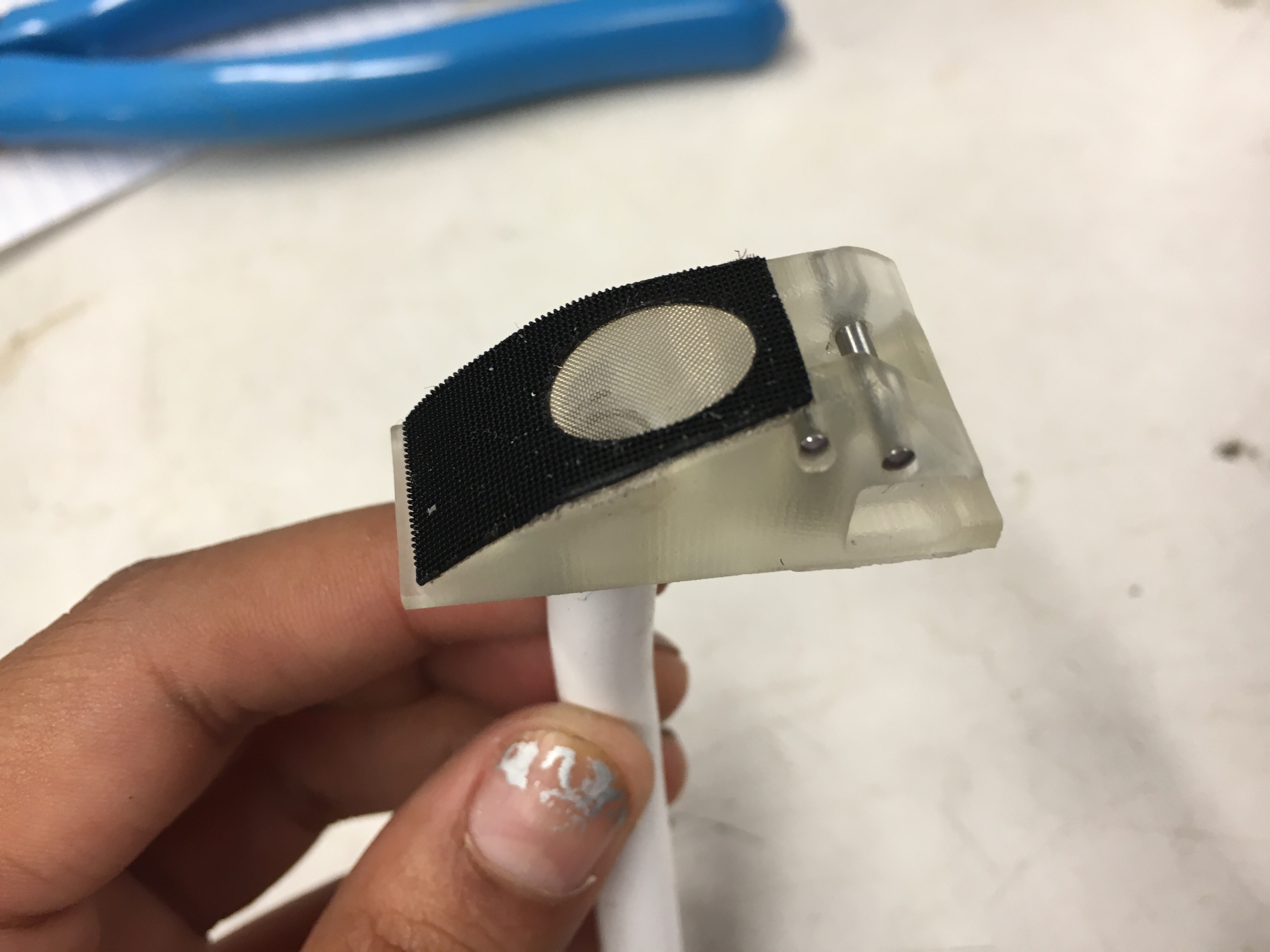
I then found the five 3D printed fingertips and superglued the different sized meshes over the suction hole and placed the black skin that I laser cut during week 1 earlier this summer in order to help keep the mesh down. As shown in the picture below, each fingertip is labeled with its respective mesh size.

7.1 Monday, August 1
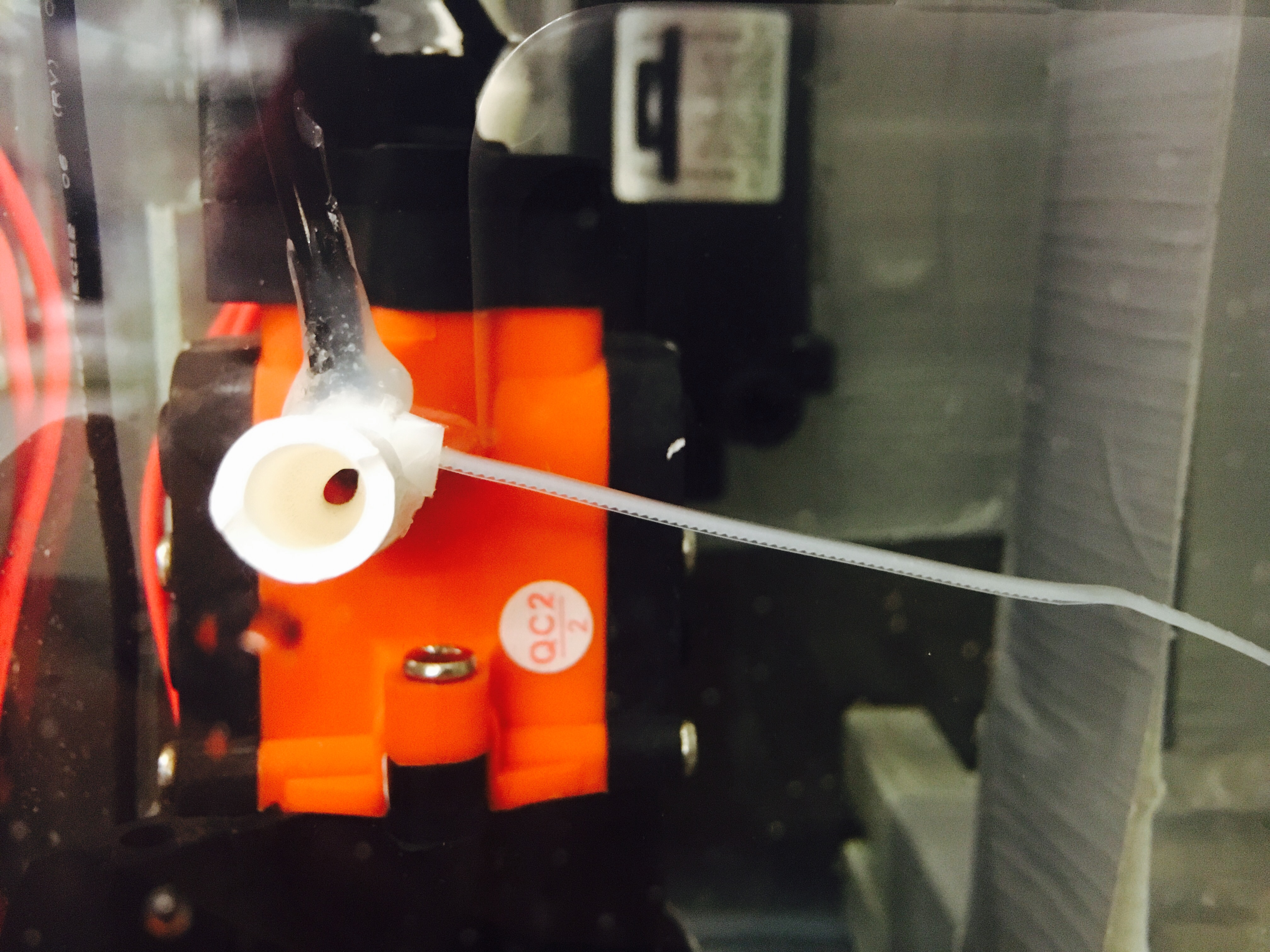
The McMaster delivery tracker said that the meshes would not be here until tomorrow so today I started setting up the other experiment I also needed to do. Hannah and I are also working on characterizing the effects of soft skin on the surface of the fingertips so I am going to redo the earlier experiments we did with for a finger tip with red rubber, black rubber (super soft), and no rubber for both the centrifugal and positive displacement pump. I started off by using Epoxy to glue the rubbers onto the fingertips:

Afterwards I set up the stage I made earlier in the program by adding an acrylic bar to the bottom that was at an angle of 5 degrees with the ground.

Once I set everything up, I decided to start gathering data with the positive displacement pump. I turned on the pump and started lowering down the fingertip. When the fingertip was about .5 mm from the bottom surface, the entire system started vibrating a lot and the ATI Nano was at Fx = -0.4lbf ~ 2N. The tolerance for the nano is ~ 2N so I immediately turned off the pump. I attempted to take the data multiple times, I also switched pumps to the centrifugal one but the vibrations did not get better.
Week Six
6.5 Friday, July 29
I started off today with a 9AM lab meeting. Afterwards, the SURIs and I met at Terman to set up for the MERL BBQ. The buns were branded (picture below!) and they were a major success! Everyone in the lab loved them and we even had some lab rivalries started within my group of friends currently interning in other MERL labs.

After finishing the clean up for MERL BBQ, I went back to lab for the last couple of hours. I decided on 5 - 12"x12" meshes to order from McMaster. I ordered a mesh of type 20,24,30,50 and 60. They did not sell any mesh 40, which was the size recommended for table salt sized particles which I think would have been useful for the sand that we had.
6.4 Thursday, July 28
Today I looked into how different people calculate the efficiency of the pumps. We will be calculating this for the rest of the trials. I know that efficiency is simply power out/power in but I was concerned about how the efficiency of the motor would affect the calculations. In the end I spoke to Hannah and we decided that we didn't need to worry too much about the efficiency of the motor. Below you can see my notes.

In the afternoon, Hannah went over the Arduino code that drives the linear slide. She showed me how to instruct the linear slide to move upwards/downwards, change the step size, and how different parts of the code interacted with each other. She also gave me some basic thumb rules to keep in mind when using the linear slide in order to keep the ATI Nano from getting damaged.
Finally, at the end of the day, the SURIs and I went to go buy food for the MERL BBQ for tomorrow. We initially went to Costco but after realizing that Costco does not take master card, which is what the BDML PCard is, we went to safe and first. I'm very excited for the MERL BBQ tomorrow because Aaron and Chris have been working on a BDML brand for our buns!
6.3 Wednesday, July 27
Today I cleaned out the water tank, it was really dirty and murky so I removed all the water and wiped the tank down. I also wanted to get access to the pumps and readjust them to more firmly attach them to the sides of the tank. While I was filling the container with water to refill the tank, the faucet knob broke and I was unable to stop the water from running. Thankfully, Arul helped me close it from under the sink and I called in a work order to get that fixed. The guy that came in said it should be fixed by tomorrow. I filled the container from a water fountain and finally set everything back up.


I also took this side view picture of the pump + ziptie to better demonstrate the length that I'm measuring and how it's restricting the flow:
Yesterday when Hannah and I discussed the results I got, we were curious if the PD pump was able to handle higher pressures and what exactly happened between 5.0 cm and 5.5 cm. We expected the plot to continue increasing upward and creating some kind of peak before it dropped down. So I decided to do three more trials on the PD pump, one each for 4.9 cm, 5.1 cm, and 5.3 cm. This plot shows my results:

It was cool to see what we expected. Yesterday the thought that the PD pump could't handle high pressures had us leaning towards the centrifugal pump, but knowing that it is able to reach the same level as the centrifugal pump makes a strong case for the PD pump. Especially when we consider that if we have multiple suction holes and one of them is blocked, the pump will push harder to continue getting the same flow through the other holes therefore probably giving us a greater suction force that could help the hand with acquisition and retention.
6.2 Tuesday, July 26
Today I started the day setting up a centrifugal and a positive displacement pump for flow rate and pressure measurements. Previously I had put the pressure lines too far down the input/output flow tubes, so I disconnected them and put the pressure lines as close as possible to the input and output of the pump, as shown below.

I measured the flow the same way I previously had, except this time I was simultaneously running the Arduino's serial monitor to take pressure data. I started with the centrifugal pump and ran 4 trials, one with no restriction to the input flow, and then I added a ziptie and measured the length of the end of the zip tie that was sticking out, the longer that length, the tighter the ziptie and the more it restricted the flow in the tube. I did the remaining three trials with the length of the zip tie at 4.5 cm, 5.0 cm, and 5.5 cm. I roughly sketched out the results:

There was a huge gap between the points when the zip tie was at 4.5 cm and 5.0 cm so I decided to do an additional fifth trial with the ziptie at 4.7 cm. As seen in the sketch, the fifth point helped us see better what was happening with the centrifugal pump. I ran the same five trials with the positive displacement pump and plotted the results from both pumps in Matlab:


http://www.pumpschool.com/intro/pd%20vs%20centrif.pdf
The description and plot below my experimental results in Matlab come from one of the papers I found last week while learning about pumps. Both the centrifugal and positive displacement pump results were what we expected to see, which made me happy.
I discussed these results with Hannah. From these plots, we can see that the centrifugal pump has a higher pressure tolerance and from my experience with running the trials, I saw that the positive displacement pump was vibrating really strongly when the flow was very restricted. This is making us lean towards choosing the centrifugal pump for our suction experiments.
6.1 Monday, July 25
This morning I came in and soldered the remaining three pumps to extensions and clips that could connect to the power source. By the end of it I was very good at getting the solder exactly where I wanted it.

I also talked over my results from yesterday with Hannah. She thought the biggest problem was probably the head loss in the tubes because were pretty long. She also thought that putting the pressure lines a lot closer to the input/output of the pump would be better for measuring head. Hannah recommended that before I start varying the pressure of the pumps and relating it to it's flow, I should only measure the flow of all the pumps, without worrying about any pressure measurements.
To do this, I decided to completely remove the tubing at the input line of the pump to minimize the head loss as much as possible. I moved the beaker to the inside of the tank so that it was much closer to the pump. I had to tape it down to three 8020 bars and place a fourth one on top of it to keep it from floating in the water. I also changed out the tubing at the output line to be just long enough to reach the top of the beaker.

As seen in the picture, I added a piece of blue tape to the 2000 mL mark so I could easily see when the water had reached that volume. To measure the flow I turned on the pump at the same time as the timer on my phone and stopped it once the water reached the 2000 mL mark. I did this for each of the four pumps. These were my results:
POSITIVE DISPLACEMENT PUMPS manufacturers flow rate: 258 L/H
| Pump | Volume [mL] | Time [s] | Flow Rate [L/H] |
| 1 | 2000 mL | 38.90 | 185.09 |
| 2 | 2000 mL | 37.57 | 191.64 |
CENTRIFUGAL PUMPS manufacturers flow rate: 500 L/H
| Pump | Volume [mL] | Time [s] | Flow Rate [L/H] |
| 3 | 2000 mL | 18.93 | 380.35 |
| 4 | 2000 mL | 18.33 | 392.80 |
The flow rates for the positive displacement pumps were really close to the manufacturers claims, and the flow rate for the centrifugal pump nearly tripled compared to what I had previously measured, it wasn't what the manufacturer claimed it to be but it definitely was a lot closer.
Week Five
5.6 Sunday, July 24
At the end of Friday, Hannah and I talked over what information we wanted from the pumps. We definitely needed to calculate the flow rate, and we were also interested in getting a pressure vs flow rate plot. The pumps had been delivered on Friday so I came in today and started to work on the pumps. I soldered one of the centrifugal pumps to extend the wires and add clips to the power supply. I hot glued the pressure lines to the white tubing and set up the pressure transducer/Arduino to take data. Then I set up the tank by taping the pump to the glass side, refilling the tank with water such that the centrifugal pump was immersed in water, and placing the 2000mL beaker next to the tank with the output tube taped to it's side. I ran one trial and these were my results:
Average Voltage reading: 3.88 V
Average Pressure: 15.36 kPa
Time: 15.54 s
Volume: 600 mL
Flow Rate: 138.97 L/H
These results didn't seem right to me because the centrifugal pump was rated to have a flow rate of 500 L/H by the manufacturer. I decided to discuss this with Hannah on Monday before proceeding with the experiments.
5.5 Friday, July 22 / 5.4 Thursday, July 21
Since we want to discuss optimizing orfice location in our paper, I spent Thursday and Friday reading published papers looking at where people have put tactile sensors on robotic hands in the past. Specifically, we're interested in finding the methodology and reasoning for choosing those locations. Not surprisingly, the majority of papers I found either only had sensors on the fingertips or focused their sensors there. Below are some of the papers I found that could be relevant:
5.3 Wednesday, July 20
This morning I was introduced to Gosia, who's in charge of our lab PCard. I placed an order on Amazon for the pumps I found yesterday. I ordered two of each of these: a centrifugal pump (a different one than the one we've been using because it would be delivered faster, we went from 650L/H to 500L/H) and a small positive displacement pump with a flow rate of 258 L/H.
After lunch I worked in CDR with Hannah. We went over an outline she created on overleaf for the ICRA paper. We both felt better about continuing the work for the summer after discussing a more structured outline of what we needed to do. The parts that I'm already working on would be choosing the right pump and mesh depending on the grain size the pump can handle. The other big things we'll focus on are optimizing orfice location and quantity, fingertip skin and shape, and distance/contact sensing.
I started looking into purchasing sand of different grain sizes however I could only find abrasives that didn't have larger sizes and came in too large of a quantity (10lb bags). I mentioned to Hannah that we could go to the beach and getting buckets of sand from both in and out of the water and filtering it out into different sizes with mesh, and although it was a random thought it seems like our best bet and something that we might do this weekend.
5.2 Tuesday, July 19
Today I spent the time before lunch putting together everything that I read yesterday. I made a summer under yesterday's date so that Hannah and I could reference all that information later. After lunch, I looked into re-ordering a few of the same centrifugal pump we've been using and sands of different grain size. Because the pump has no specifications on the concentration or size of debris it can handle, we would like to run an experiment to get this data for the paper.
I then spoke to Hannah about what I found and learned about pumps yesterday. We went over the pros and cons of each one with respect to our application and I think we're both on the fence about which pump would be best. We leaned towards centrifugal for a bit and then changed our minds to a positive displacement pump but in the end we decided to order one of each and test it out in our experiments to see which one performs better.
5.1 Monday, July 18
This morning I spent some more time doing SolidWorks tutorials, I learned how to mirror parts, import parts from the library and work with different types of fillets to create a door knob. After that I started looking into the different kinds of pumps to learn how they work, debris influx limitations and what conditions cause cavitation. I spent the day reading through articles and watching youtube videos learning about each pump. I wrote a summary below for future reference.
How it works
Centrifugal Pump: A centrifugal pump works by raising the pressure of the liquid to induce flow. An impeller at the center of the pump is immersed in the fluid and rotates, in turn making the fluid rotate with it. The pressure of the rotating water increases and the pressure at the center of the impeller decreases. The low pressure at the eye of the impeller sucks water into the system, continuing the process.
Positive Displacement Pump: While there are multiple types of PD-pumps, the general idea comes from a suction cycle. For a piston pump, as the piston moves up the pressure decreases and sucks fluid into the pump. The piston then moves down, the pressure in the pump increases which closes the suction valve and pushes the fluid out through a discharge valve. The diaphragm pump works very similar to a piston pump, the only difference is that instead of using a piston/plunger to move the fluid, a diaphragm is used.
After understanding how pumps work, I looked into the specific pump we have been using in our experiments. I couldn't find any information regarding its debris limitations or what happens if the input line is blocked, such as cavitation. Knowing that we use a centrifugal pump, I started looking more into the selection of centrifugals and their uses. I ended up on multiple industrial sites. They were all seemed to be in agreement that the standard centrifugal pump is only equipped to handle clean water with little to no debris. Centrifugal pumps that were able to handle larger quantities of debris in water were really large, heavy, and expensive. For our purposes it wasn't helpful to continue looking at these pumps designed for industrial use. However, these sites did mention that a diaphragm pump would be the most versatile choice for handling debris:
- Pam Meyer, Choose the Right Pump for Any Job
I kept in mind that these were construction sites, so they were probably referring to large diaphragm pumps and these claims may not apply to smaller pumps, but it sparked purpose for further reading into smaller scale diaphragm pumps and their limitations and how they compare to centrifugal pumps.
Picking a Pump

To the left, is a chart that I found that may be helpful in deciding which type of pump to use. Regarding cavitation, centrifugal pumps are a lot more likely to be damaged by cavitation than positive displacement pumps. Cavitation itself is a lot more likely to occur in centrifugal pumps. PD pumps don't usually reduce pressure below the fluids vapor pressure, which according to Allen Inks on Quora, is when cavitation occurs.
When to Choose a Positive Displacement Pump 
Working of Centrifugal Pumps
http://www.learnengineering.org/2014/01/centrifugal-hydraulic-pumps.html
Understanding Positive Displacement Pumps
http://www.pumpscout.com/articles-expert-advice/understanding-positive-displacement-pumps-aid89.html
When to use a Positive Displacement Pump
http://www.pumpschool.com/intro/pd%20vs%20centrif.pdf
BLDC Pump: DC40 Series Data Sheet
http://www.bldcpump.com/downloads/DC40.pdf
Vovyo Technology, Brushless DC Pump: DC40 Series Product Specifications
http://www.dcbrushlesspump.com/Brushless-DC-Pump-p26.html
Choose the Right Pump for Any Job
http://www.forconstructionpros.com/article/10616858/choose-the-right-pump-for-any-job
Picking a Pump
http://www.wwdmag.com/pumps-centrifugal/picking-pump
Centrifugal Pumps vs Positive Displacement Pumps
http://www.blackmersmartenergy.com/comparativedata/centrifugal-pumps-vs-positive-displacement-pumps.html
Centrifugal Pump Systems Tips
http://www.pumpfundamentals.com/centrifugal-pump-tips.htm
Preventing Cavitation Centrifugal Pump
http://www.engineersedge.com/pumps/preventing_cavitation.htm
Why does cavitation occur in centrifugal pumps and not positive displacement pumps?
https://www.quora.com/Why-does-cavitation-occur-in-centrifugal-pumps-and-not-in-positive-displacement-pumps
Week Four
4.5 Friday, July 15
I met with Hannah an hour before lab meeting today because we were presenting our work so far and wanted to make sure we had everything we wanted to talk about. I had a couple slides I was going to present, including the work on the stage I built and the data that I gathered from the angle experiments this week. During meeting we got a lot of really great feedback and thoughts, particularly from Arul, Capella, and Will. Hannah and I met afterwards to discuss everything that was brought up. We needed to rethink what we wanted to accomplish for the remaining part of the summer. There were so many different avenues we could dive deep in or different things we could combine to improve the hand as a whole. There was the possibility of continuing to focus on optimizing the fingertip by potentially adding more holes and attaching a sensor to each one to characterize contact. Or we could focus on trying to figure out what would be the most useful use of suction on the entire hand for object acquisition. We decided that taking a step back and looking at the entire hand would be more impactful and interesting for our audience. For the remainder of the summer we're going to proceed with standardizing the variables in the experiment setup, study how the tubing length affects the suction flow/force (potentially with the assumption that the pump will be attached at the robot's shoulder), study different 'skins' (rubbers) on the fingertips and hand, and continue characterizing event detection: no contact/contact, fingertip angle, potentially 'how many contacts?' if we decide to add more holes on other phalanges, and creating more manipulation videos.
For the remaining part of the day, I helped Hannah look into various pressure sensors but ultimately decided to focus on the suction flow going through the tubes rather than the pressure.
4.5 Thursday, July 14
This morning I retook the videos from yesterday, except this time I used a fingertip with a smaller hole. After speaking to Hannah, we predicted that a smaller suction hole would be more sensitive to smaller angles, which is something we want to look at more closely. In addition, the angle I recorded yesterday was the one when the fingertip moves from side to side, whereas on the hand, the fingertip will more realistically rotate forward and backward so I needed to re-do the experiment with the correct angle. The graphic below shows the angle that I would be measuring in Matlab later on.

I took four trials, two with the passive, second fingertip clogged and two with it relaxed and open in the water. Afterwards, I spent the day post-processing the data in Matlab. I came across a few challenges, opening the video on a Mac didn't allow me to pause it and look at the frame number so I had to open it in iMovie and scroll through frame by frame to the one at the beginning of the time (in s) that I was interested in starting to analyze. I also came across an issue when plotting pressure vs angle I could tell that the data was misaligned but I couldn't figure out where the misalignment was coming from. I figured out that the time data was not perfectly recorded second by second, there were a few skips in time that could account for error when I was grabbing data from the time matrix every 250 rows (because the LED flashed every 250 ms). However after fixing this, the data still didn't make much sense. I stayed late with Hannah going through the code and after a couple hours we finally found what was wrong! All our frame to time conversions were correct, we just forgot to subtract the time at the beginning of the video when the serial monitor in Arduino is not running and collecting data. After fixing this offset, we ended up accidentally not converting seconds to milliseconds correctly but after a few minutes we quickly figured that out and were able to get a plot that made sense. Despite it being a really preliminary experiment and having some noise, we were able to see a clear trend between angle and pressure. We were also able to get pretty good sensitivity at small angles all things considered. Moving forward we are going to run experiments with a more robust and rigid structure to get more accurate and less noisy data.
4.3 Wednesday, July 13
I started off today by continuing to practice my SolidWorks skills, I went through a couple tutorials and learned some new handy techniques and different approaches to achieve the same thing. After a couple hours of this, everyone in lab and I went to Dr. Kramer's presentation on soft robotics. It was a really interesting talk, she was great at making the presentation engaging and explaining what she was working on in a clear and concise manner. I found it particularly interesting because I had never heard of soft robotics before and it seems like it's going to continue to be a huge topic in the future of robotics. It was also just really great seeing such an accomplished young woman in engineering!
After the talk, Hannah and I talked over our data from yesterday. We found our last trial to be the most interesting because we could clearly see in the graph when one of the fingertips instantly made contact with the block while the other fingertip took some time to make the contact. We also saw the same trend in pressure in both fingertips as we curled the fingers upward making the fingertips be at an angle with the surface. This made us decide that our next step was to do some very preliminary experiments to study the pressure/flow as the angle of the fingertip with the surface varied.
I removed the stage from the tank and set up the pump and pressure transducer/Arduino to take data. I also set up my phone that faced the edge of the tank as straight on as possible to get a flat line to be able to measure the angle later. In addition, I flashed an LED every 250ms so that I would be able to pair up the video and numerical data together after the experiment. I ran 6 trials, taking time, pressure, and the video as my data. The graphic below shows the set up and the angle I will measure using Matlab.

4.2 Tuesday, July 12
I worked a lot with Arduino and circuits today! Hannah and I want to start experiments with two fingers with both fingers having a suction tube. We only had one pressure transducer on a board, so I started by making the second pressure transducer circuit. I soldered the pressure transducer on a board, then soldered the voltage source, ground, and analog output wires onto the board. I really enjoyed building the circuit, even if was a simple circuit.


Afterwards, I connected both pressure transducers to an Arduino uno and an LED light and started a new script that would read in data from the pressure transducers and flash an LED at the same rate. We did a test run with only one of the fingertips having suction, because we were waiting for the second barb+neck for the other fingertip. Everything worked well, after post-processing the 3D printed tube barb + necks, we stayed late to do a few trials. We saw a couple failures when the fingers kept pushing inward. At first glance, the data seemed to correlate to what we've seen from the pressure sensors before.
4.1 Monday, July 11
The majority of today was spent on SolidWorks. I laser cut a base for the stage with holes to screw on triangles. I installed the base onto the stage and made sure to lift the entire structure a couple centimeters to make sure the fingertip wouldn't clash with the raised base. I also designed various right triangles with varying angles between the base and the hypotenuse to test the fingertip suction force at different angles. Hannah and I decided to start with 5, 10, 15, and 20 degrees for the triangles.
Afterwards, I designed a part with 4 barbs for the pressure sensing tubes and the suction tubes with different neck sizes between the 2 barbs for the pressure sensing tubes. Hannah showed me how to take the SolidWorks files from McMaster, import them into my part, and combine all components as one part. The suction tube barb was 4.5 mm in diameter, so we made the part with a neck size of 2.5, 3.5, and 4.5 mm. We want to study how the neck size affects the suction force and pressure sensor in order to standardize the neck size for all of our future experiments.
Week Three
3.4 Friday, July 8
Today started off with lab meeting at 10:30, Arul presented his work on adhesives and then showed us OnShape which is really useful for creating 3D structures by creating the connection cuts between 2D parts that can easily be laser cut. Afterwards, I met with Hannah to discuss the data that was taken this morning, we noticed there was vibration happening in the acrylic beams that was adding noise to our data. We decided to redesign the acrylic setup to be made out of 8020 to increase the stiffness. We then headed to the first MERL bbq together, where I met up with other SURF students.
After lunch, there was a tour of middle schoolers. Hannah and I talked about the underwater hands and I was able to say a little bit about how the under actuated fingers worked. I was glad that the kids seemed interested in what we had to say. After they left I begun working on redesigning the setup by creating an assembly in SolidWorks. Mark came to check-in with me and he had a much faster and easier idea to substantially increase the stiffness in the acrylic. He super glued long metal bars onto the acrylic. The bending moment was clearly reduced, there is still some bending happening but we believe it is as close to perfect as we can get it.

I'll be ordering a triangle protractor from McMaster next week to get started on our next experiment.
3.3 Thursday, July 7
I started off the day by post processing the new fingertips that Hannah 3D printed yesterday. I put them in the oven, cleaned them in the oil bath, and washed them out, making sure all the small holes were completely clean. I reassembled the stage, adding in the second acrylic bar across the bottom, and prepared the setup for our second set of testing. We continuously took data this time, as opposed as starting and stopping the Arduino serial monitor with each increment of distance.

After lunch, Hannah worked on separating out the data while I worked on documenting our current set up. I photographed it from different views and clearly described it's function. I am also working on making an addition to our stage that will allow us to change the angle of a surface for our upcoming experiment.

3.2 Wednesday, July 6
Today Hannah and I talked about the data we collected yesterday and compared it to suction flow data she had gathered in the past. We decided that there was a lot of noise and not enough sensitivity near zero to detect wether the fingertip was in contact or not. Our hypothesis is that because the hole in the fingertip is not completely flat (it curves with the finger near the end), there is a significant amount of flow even through that curved hole that isn't covered when the rest of the hole is. Another problem that could be happening is with the pump not being completely sealed to air or the pressure sensor not reading a zero value. Hannah redesigned the fingertip so that the hole is flat. Meanwhile I tested the pressure sensor to see if it can detect when my finger completely covers the hole.
In addition, we wanted to expand the width of our stage so I edited the solid works file for the acrylic back base and laser cut it on thicker 6mm acrylic to increase the rigidness. However, after expanding the width of our stage, it no longer fit in the tank of water. The easiest way to fix this was to hacksaw the two 8020 bars acting as feet of the stage. After reassembling the entire stage we also noticed that the expanding of the width of the acrylic back made the entire structure less rigid. I created another acrylic bar that would connect the bottom two 8020 feet, such that it would be perpendicular to the acrylic back and significantly cancel out the bending moment.
3.1 Tuesday, July 5
It was an exciting start to the upcoming week because today we were finally able to start gathering data form our first experiment! After lots of work fiddling with the set up, screwing things upside down and backwards, it was nice to finally get to use the structure.

I started the day off by finishing up the designs for the pieces that would be used to set up of the ATI nano into our system. I laser cut the parts out of 3mm and 6mm acrylic. I'm really happy because I feel a lot more comfortable using SolidWorks, I've learned a couple tricks using the linear and circular hole patters. What took me 2 hours the first time around, now takes me less than 30 minutes. I've also had to use the laser cutter so I know my way with it pretty well.
The rest of the day was spent putting together the set up, tweaking it to be as near perfect as possible and making sure everything worked well for gathering data. When we finally started our experiment, Hannah took care of gathering data from the ATI nano and controlling the motor/linear slider with an Arduino duo while I was in charge of gathering data from the pressure sensor on an Arduino uno. We took data varying the distance between the fingertip and the bottom of the tank from 0-1mm in 1/10mm increments. First thing tomorrow, we'll start analyzing the data to see where to go from here, but at first glance we were able to see a potential trend!
Week Two
2.3 Friday, July 1

2.2 Thursday, June 30
My task was to create a stage that would hold the motor + linear slider in a way that we could immerse the fingertip into the water without damaging the equipment with water. So today I figured out the measurements I wanted the experiment stage to have. I designed the back plate shown to the left in SolidWorks. It allows the motor and linear slider to be firmly and rigidly mounted on 8020 bars.

Afterwards, I worked on putting together the 8020. The first setup had 3 L's at the bottom acting as "feet." I thought this would make the stage easier to move and set down anywhere. However, the weight of the motor plus the large concentration of force at the feet made us nervous about the risk of cracking the bottom glass and the instability of the stage so I changed the setup. This second setup had two long bars at the bottom, their bottom face was covered with duct tape to protect the tank's glass, and the length helped stabilize the stage.

2.1 Wednesday, June 29
After our lab retreat on Saturday, Hannah and I came up with a more thought-out outline of what we wanted our steps and goals throughout the summer to be. We decided to leave the mesh experiment for later, and begin by focusing on the change in the suction force and pressure with variance in distance from contact with a surface. I started by getting familiar with the arduino uno pressure sensor! I figured out what the numbers it was outputting meant and coded a script that converted those integers into pressure in [kPA]. That was really fun, I really enjoy working with the arduinos.

Afterwards, I designed an extension to the linear slider carriage that would increase the distance between the motor+linear slider and the fingertip (which needs to be submerged in water). I scavenged for acrylic and laser cut the extension. Then I attached it to the carriage and the fingertip as shown below:

Week One
1.3 Friday, June 24
Today I used the laser cutter on my own for the first time! Luckily nothing was set on fire and I successfully cut out the rubber for the fingertip. I also added a mesh to the fingertip as a solution to filter out debris from a real environment during suction. Some of the future work this summer will be testing different hole sizes in mesh in murky waters to determine the best mesh that we should use that will successfully filter out debris without significantly compromising the suction flow. I set up the fingertip for testing by superglue-ing the spring+tube that I put together yesterday to the finger.
1.2 Thursday, June 23
Today was really exciting! We finally started working on the hand and I got more hands on time with the project. Hannah showed me the set up we're aiming to begin with to see if we can really detect contact not the finger tip with a suction flow sensor. She also 3D-printed four fingertips and showed me how to properly remove the wax in the oven and oil bath. I was then given the unexpectedly tedious task of putting a string inside a plastic tube which will be used as our suction tube in the fingertip.
After lunch, Hannah gave me a quick crash course on SolidWorks, which I've really been wanting to learn how to use. I spent quite some time working on creating the sketch for the fingertip with a hole for the suction tip. But after a couple of hours I got some help from Hannah and we were able to successfully export the file to a .dxf!

Overall it was a good day. I've learned a lot in just one day. I'm looking forward to increasing my familiarity with SolidWorks, using the laser cutter on my own tomorrow and to our next step: working with the Arduino's for our sensors.
1.1 Wednesday, June 22
Today was my third day in the lab, I feel like I mostly know my way around and am familiar with the space, especially after yesterday's lab clean up.
This summer I will be working with Hannah on her underwater robotic hands project. Specifically, I will be helping her do research on implementing suction tubes into the fingertips for inflow and using a pressure transducer to detect wether the finger has made contact with the surface of an object. We expect that the suction tubes and sensors will help increase object acquisition and retention.
I started the week by reading a couple of articles published by Hannah to get familiar with the project. I also received a laser cutting tutorial from Alice with the SURIs in the School of Education. After lab clean up yesterday and up until today I have been working on looking for articles related to suction flow contact sensors. I've browsed through a variety of different articles, and stumbled through some interesting ones. I found this one that is similar to the gecko adhesive work that has been done in the BDML before, but focuses on clingfish!
Stick tight: suction adhesion on irregular surfaces in northern clingfish
http://rsbl.royalsocietypublishing.org/content/9/3/20130234.short

I also found multiple articles that seemed promising for our future work but for the most part it seems like suction flow for this particular application is pretty novel, which is cool.
VacuumTouch: attractive force feedback interface for haptic interactive surface using air suction
http://dl.acm.org/citation.cfm?id=2557252
Study on air inflow of a passive suction cup
http://ieeexplore.ieee.org/xpls/icp.jsp?arnumber=6739649
Hand-arm coordination for a tomato harvesting robot based on commercial manipulator
http://ieeexplore.ieee.org/xpls/icp.jsp?arnumber=6739884#references
Development of robot hand with suction mechanism for robust and dexterous grasping
http://ieeexplore.ieee.org/xpls/icp.jsp?arnumber=6697153#fig_7
Biomechanics and hydrodynamics of prey capture in the Chinese giant salamander reveal a high performance jaw-powered suction feeding mechanism
http://rsif.royalsocietypublishing.org/content/10/82/20121028.short
Pressure Switch for Dust Sensor and Vacuum Cleaner
http://www.freepatentsonline.com/y2016/0100732.html