new web: http://bdml.stanford.edu/pmwiki
TWiki > Rise Web>ClimbingRobot > ProjectManagement > GumbyBot > ToyBot04 > ServoDriverController>GaitPlanner (23 Jun 2006, BarrettHeyneman)
Gait Planner (for StickyBot)
Version 4 Version 5 Version 6Version 4.x
A gait planner has been written to quickly generate gaits for StickyBot. This Matlab script allows the user to specify relative leg timings, individual offsets for all of the servos, and magnitudes of motions. Once a suitable gait is found, it can be written to a*.DAT file, which is readable by the ServoDriverController PC software (ver 2 or 3). The ServoDriverController software can then be used to program this gait into the ServoDriverController board. (NOTE: Ballpark values are given for all variables below, which creates a four-stroke gait.)
- GaitPlanner Matlab software: GPlan_v43.zip, GPlan_v44.zip, GPlan_v44a.zip (slimmer for viewing on lab Gateway laptop)
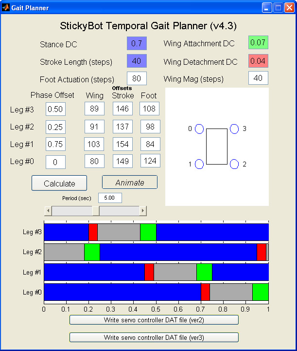
Leg Timing
All of the legs obey the same basic timing for each period. Currently, there are 4 major zones within each period.- Stance - (BLUE) legs are on the climbing surface and working at moving the body up the surface; wing angle is relatively static
- Attachment - (GREEN) legs are moving wing angle toward the wall to make contact; stride is relatively static
- Detachment - (RED) legs are moving wing angle away from the wall to break contact; stride is relatively static
- Swing - (GRAY) legs are not in contact with the surface and moving to reach a position to make another stride; wing angle is relatively static
'Stance DC', 'Wing Attachment DC', and 'Wing Detachment DC'. After changes, the 'Calculate' button can be used to update the temporal display at the bottom of the GUI. - Ballpark values:
Stance DC0.7, =Wing Attachment DC0.07, =Wing Detachment DC=0.04
Leg Phasing
The timing for each leg can be shifted relative to a fixed time origin in order to create a wide range of gaits. The gait timing is normalized on a [0,1] scale, and all timing related variables are given in terms of duty cycle (DC). Changing the 4 parameters labeled'Phase Offset' will shift the various leg timings and create different gaits type. After changes, the 'Calculate' button can be used to update the temporal display at the bottom of the GUI. - Ballpark values:
Phase Offset[0,1,2,3] (legs) = [0, 0.75, 0.25, 0.5]
Motion magnitudes
The three actuated degrees of freedom on each leg are controlled by three individual servos. The magnitude of the wing action, stroke length and foot actuation are all given in terms of servo steps. (NOTE: In the ServoDriverController software, 2 servo steps equal 1 degree of rotation.) These magnitude variables are'Stroke Length', 'Foot Actuation' and 'Wing Mag' in the Matlab GUI. These variables are used when actually writing the output (DAT) file, and are not represented graphically in the GUI. - Ballpark values:
'Stroke Length'40, ='Foot Actuation'80, ='Wing Mag'=40
Motion offsets
Each servo has an offset, and can be adjusted via the 12 offset variables (sorted by leg, wing, stroke, foot). Since each servo was individually connected to its designated degree of freedom, it contains a different offset. The offsets tell the gait planner what position to use as a base value, and determine what range of motion a degree of freedom will operate within. The base value is changed (added to or subtracted from) by a value relative to the various magnitudes.- Ballpark values:
| Wing | Stroke | Foot | |
|---|---|---|---|
| Leg 3 | 89 | 146 | 108 |
| Leg 2 | 91 | 137 | 98 |
| Leg 1 | 103 | 154 | 84 |
| Leg 0 | 80 | 149 | 124 |
Speed (Gait Period)
The approximate gait period can be controlled with the'Speed' variable. (NOTE: The animation is not real time! It depends on your computer.) Each sequence for the ServoDriverController currently can handle 256 frames, each with positions for 12 servos. The minimum frame rate is 20ms for the servos. If a desired gait period results in over 256 frames at 20ms, the frame rate is increased to space the frames over the entire gait. - Ballpark value:
Speed=5 secs
Graphical displays
A normalized temporal display of the leg motion is displayed at the bottom of the GUI, and a body representation in on the right side of the GUI. To get an idea of how these gaits look in action, the'Animate' button can be used to play the gait. (NOTE: The animation is not real time!) The 'Speed' slider will allow you to continuously change the playback speed and gait period for a particular gait.
Version 5.x
- GPlan v5.x Matlab Software (Descriptions/Explanations below): GPlan_v5.0, GPlan_v5.1, GPlan_v5.2, GPlan_v5.3
Version 5.0
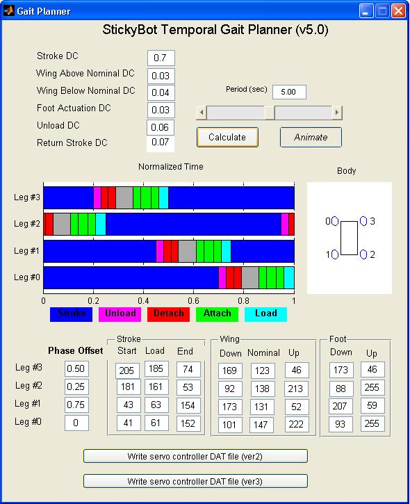
Version 5.0 drastically changes the interface for GPlan. Servo values for all points of interest are directly specified in order to handle differences in servo command-to-position ratios. In addition there are a few more distinct phases within an individual leg's motion; specifically loading, unloading, and wing depression for aiding attachment. The duty cycle can be specified for stroke (as before), as well as motion of the wing above nominal, motion of the wing below nominal, unloading, and foot actuation. Generated gaits can still be written to a*.DAT file for version 2 or 3 of the PC ServoDriverController.
The visualization is less than ideal, but the following phases are indicated by color: - Stance - (BLUE) leg is on the climbing surface and working at moving the body up the surface.
- Loading - (CYAN) leg is on the climbing surface and pulling faster than the other legs in order to load itself.
- Attachment - (GREEN) leg is moving the wing down to the attachment position, and/or uncurling the toes to make contact.
- Unloading - (MAGENTA) leg has stopped moving and the motion of the other legs is unloading it.
- Detachment - (RED) toes are uncurling to break contact, and/or the leg is moving up away from the wall.
- Swing - (GRAY) legs are not in contact with the surface and moving to reach a position to make another stride.
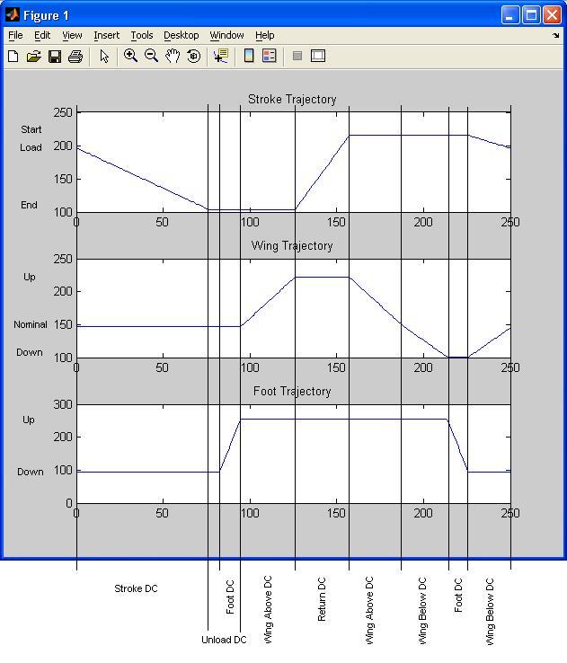
 A graph of the three trajectories for a single leg is shown below to demonstrate how the DC and position values are used to generate them. The only non-obvious part is the overlap between Unloading DC and Foot DC (toes unloading). The unloading phase (of length Unload DC) always starts right after the stroke phase (Stroke DC), and the toes unloading (Foot DC) always ends at the same time as the unloading phase.
Version 5.1
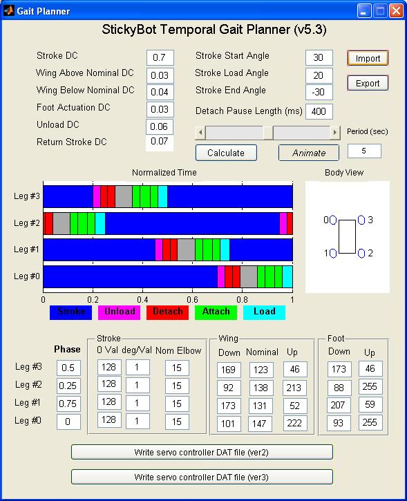
In version 5.1 the stroke trajectory is no longer calculated based on linear interpolation of commanded positions, but instead based on constant vertical velocity. The user inputs stroke angles for all legs (measured from horizontal towards StickyBot's head), nominal elbow angle (measured away from parallel to body) for each leg, and individual servo parameters; zero value (upper arm perpendicular to body) and degrees per commanded value.
Version 5.2
In version 5.2 there is a user specified wait to be included after the toes on each foot have been commanded to be fully up. This allows high resolution during important motions (ie stroke) while giving the toes plenty of time to fully detach themselves before the leg is lifted. -- BarrettHeyneman - 31 Mar 2006
Version 5.3
Added the option to export and import all the editable text settings as*.gpn files. The files are mostly unreadable (the values are in no discernable order, having to do with the order that the uicontrols come up in matlab as they are cycled through the handles structure). Things may break if you try to load a random file, or one that isn't properly formatted, but exported files do import correctly.
 -- BarrettHeyneman - 05 Apr 2006
Version 6.x
- GPlan v5.x Matlab Software (Descriptions/Explanations below):
Version 6.0
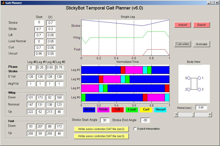
Version 6 is the latest (and hopefully last) major overhaul of the gait planner for StickyBot. Because of better toes giving us much more anisotropic adhesion, it seems that the next important step is to play with the relative timing of certain elements of a single leg trajectory. This includes when to curl the toes relative to lifing the wing relative to stopping the stroke and/or starting the swing (to name a few). The previous versions of GPlan have been rather rigid in those relative timings, and version 6.0 addresses that.Trajectory Generation
The user may now input the start and duration (in normalized time space) of 6 different elements of the leg trajectory (2 per motor). This includes:- Stroke - The stroke motor is moving the leg from the head towards the tail.
- Stride - The stroke motor is moving the leg from the tail towards the head.
- Lift - The wing motor is lifting the leg away from the climbing surface. The DC for this element is also used for when the wing motor brings the leg from above, down to the climbing surface.
- Load Normal - The wing motor is depressing the leg into the climbing surface in order to preload the toes and help with attachment. The wing is brought from above, down to the climbing surface immediately before the start of this element. The leg also immediately returns from the loading position to nominal, with the loading DC.
- Curl - The toes curl up, limiting their contact area.
- Uncurl - The toes uncurl and lay flat, maximizing their contact area.
Visualization
There is an added graph which displays the trajectories for the three motors from one leg so that the user can determine if relative timings of trajectory elements are as desired. The normalized time graph has had some changes so that all controllable elements of the trajectory can be seen. Stroke motor sections are overwritten by foot motor sections, which are overwritten by wing motor sections. (This was done so that there didn't have to be 12 different lines, 3 for each leg). The colors indicate the trajectory elements described above, with the addition that gray indicates the stroke motor not moving. The body plot has had the legs renumbered to match the system agreed upon by Johnathon and Sangbae.Output
GPlan will still output to a*.DAT file for version 2 or 3 of the PC program. Since the new legs for StickyBot have different geometry, the stroke motion is once again simply linearly interpolated. There is also the option to force an explicit interpolation to the smallest time step possible in the output of GPlan. The newest firmware for StickyBotController will linearly interpolate on the fly, so if the explicit interpolation checkbox is blank, the output of GPlan will simply be the points of interest.
 -- BarrettHeyneman - 14 Jun 2006
Add Ons
- JKarpick has created GestureTweak to create and modify special motions within a gait
Ideas, requests, problems regarding TWiki? Send feedback