new web: http://bdml.stanford.edu/pmwiki
TWiki > Rise Web>StickyBot>StickyBotController (11 Jul 2008, BarrettHeyneman)
Open Loop Control
Controller
ServoDriverController?Gaits
GaitPlanner? GestureTweak?Debugging
-- JonathanKarpick - 15 Mar 2006 Working on debugging the current perf board 252-based version on Main.StickyBot- Installed MPLAB on the Gateway laptop (fett) - can now use ICD2 via the laptop for debugging (assuming the on-board circuit allows for debugging, but that's another step...)
- Re-compiled v3.0 of firmware and compared with what was loaded on PIC - did not verify, so I re-programmed the PIC.
- "Re-installed" the PC Servo Controller Software - Virgilio mentions that you should drop the v3.0 executable into the same directory as all of the other dlls and v2.0 executable, which we weren't doing.
- What the LEDs SHOULD be doing:
- Start-up: Green -> Red -> Green, 1/2 second each
- Timer-on: Green on
- Timer-off: Green off
- "Key 3 Press Routine": Red on for 1 second
- "Timer Mov On": Red on until "Timer Mov Off"
- Using v2.0 firmware and PC software, still cannot "read" from the flash once programmed - looks like an infinite loop of max commands to the servos (which matches what the robot does when you first try to run the gait).
- SOLVED: DO NOT "CONNECT" (green button) to robot before flashing the gait to the servo controller.
- Still an issue with running the gait and having it stop after a number of cycles - not quite sure why it does this. You can see it with my test "push-up" gait. At first look, it varies with load on servos. Hardware issue? Are we running servos from the voltage regulator? If so, that may be an issue.
- Made a MATLAB based GUI to tweak v2.0 Main.StickyBot gaits: GestureTweak?
- There is a MATLAB based GUI to create v2.0 and v3.0 Main.StickyBot gaits: GaitPlanner?
- Modified circuit board to support In-Circuit Serial Programming (ICSP) and In-Circuit Debugging via the phone jack.
- Slightly modified Virgilio's v2.5 code to allow for in-circuit debugging. (It disables commands to pins 27 and 28 when DEBUG_MODE has been #define'd).
- Re-arranged the firmware locations on the laptop - the shortcuts on the desktop now take you to c:\users\jkarpick, where the files are. (MPLAB has an issue with paths being too long...)
- If you want to program and/or debug you can either use the power from the ICD2 or use a power supply plugged in as you normally would run the robot.
- Ensure that whatever method you choose that you run the "MPLAB ICD 2 Setup Wizard" from the Debugger or Programmer menus and ENSURE that you've chosen the correct "Target has own power supply" or "Power target from the MPLAB ICD2." It's bad for the puck if you're using an external power supply and the puck is trying to power the whole thing...
- If you're using an external power supply, unplug the 2nd servo connection from the left (labeled #2). The programmer/debugger shares these pins and I'd rather not send weird signals to the servos.
- I've replicated the issue of trying to program gaits onto the PIC and read them back. Sometimes it works, sometimes it's really noisy - looks like its dropping data somewhere along the way.
- Need to figure out how to use the ICD2 to read what's been programmed into flash. This should help isolate the problems to the write sequence, the read sequence, and whether the issue is with the PIC, the PC, or the connection.
Closed Loop
-- JonathanKarpick - 28 Apr 2006 StickyBot Controller Board: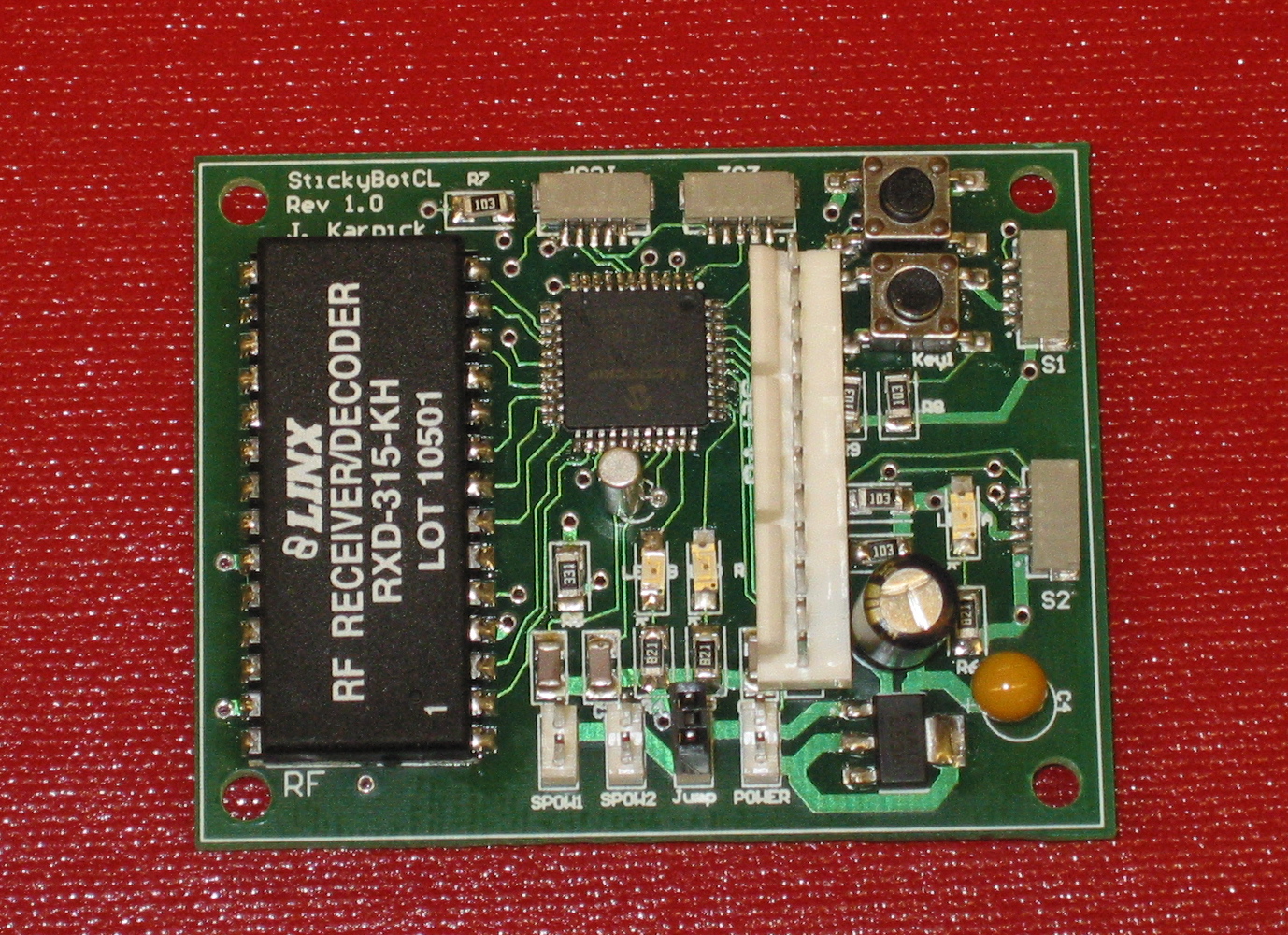 StickyBot Sensor Board:
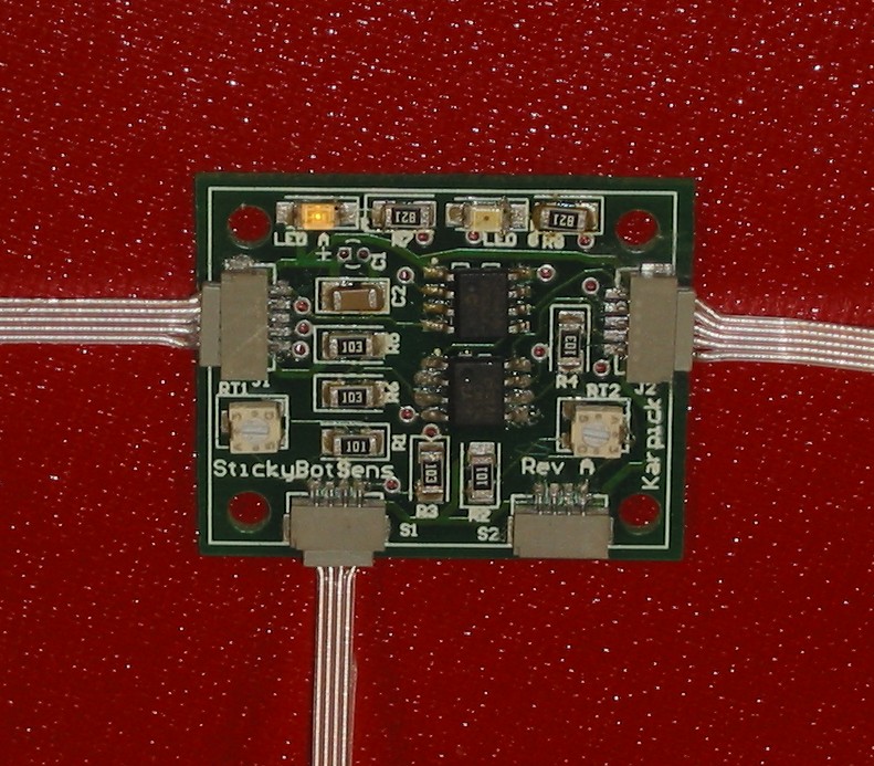
Notes
The main program is found in ServoMain.c, which is also where the control algorithm is found (named Control()...). Right now, I've just been goofing with what goes in there, so don't pay it too much mind. The phone cord from the ICD2 plugs right into the adapter which is plugged in to the controller board. 5-6V servo power gets attached to the free wires hanging off of the SPOW1 jack - this only powers the servos, the board will pull power from the ICD2. The jumper ("Jump") should not be shorted - this keeps the power to the servos separate from the board power. Currently, the sensors are not "calibrated" - if you pay close attention, you can see that the servos move different amounts depending on which sensor you're playing with. This function should be done in the servo board firmware. Ultimately it could be automated... but it's not now.Schematics / Assembly
Schematics and PCB assembly drawings are here:Firmware
- CLServoControllerC.zip - C Version of Firmware. Should help with control law development...
- Good to go - the linker script required modifying to ensure that no program code was placed in the gait storage area. Flash writes and reads appear to be working well.
- For Open Loop operation, just comment out the majority of Control(). Just leave the copy from gValueServ to gValueCmd in there.
- The C18 preprocessor is annoying. Don't ask it to do any math for you - it'll mess it up. You may notice that a lot of my #defines are commented out and replaced with fixed numbers due to this "feature."
- A first attempt to optimize the linear interpolate function (InterpolateOptimization? ) has improved the speed of Interpolate() from ~1.1 mSec to ~0.2 mSec. (-- SalomonTrujillo - 15 Jun 2006)
Issues
Current things to work on:- Automated sensor calibration?
- Modify initialization of gRamBuff as gRamBuff[256] instead of gRamBuff[64] as it currently is in ServoMain.h / ServoRoutines.h so that the linker doesn't try to put it anywhere near the special function registers.
- I think this is handled in my version of the linker file, but I'm not positive.
- Review loading two bytes into a long:
I usetempCounter = ((unsigned int)(gTOC[0])<<4) + (unsigned int)(gTOC[1]);
Virgilio recommends:tempCounter = (((unsigned int)(gTOC[0])) << 8) + (unsigned int)(gTOC[1]);
I think I'm right on this one... - Virgilio noticed my use of 32 byte writes to Flash RAM. This is specific for the 4520 (via errata) and should be 64 for other chips...
- Should erase all of the flash memory area - not just the length of the current gait data. This is really aggravated by my setting of the un-used gait memory to 0x00 in the linker...
- Don't need to enable GIE at the end of the writing function as it will be enabled when the program returns from interrupt.
Improvements/Thoughts
Improvements to the boards:- Controller Board:
- Vpp pin on the S1/S2 connectors is currently tied to ground. THIS IS BAD!! If connected, the sensor PIC will be held in reset mode...
- Workaround: make the sensor wires w/ only 4 lines - do not connect the 5th.
- S1/S2 connectors only need 4 lines
- 232 jack only needs 4 lines
- Servo bus header
- Cap C5 is currently under the servo header (oops).
- Smaller/low profile connectors (JST to keep things consistent?)
- More space for friction-lock power connectors (the power connectors probably should NOT get smaller, but can go right-angle if desired...)
- Oscillator holes (Y1) can be closer together
- Smaller dimension caps (C3 in particular)?
- Flip ICSP jack (see below...)???
- Vpp pin on the S1/S2 connectors is currently tied to ground. THIS IS BAD!! If connected, the sensor PIC will be held in reset mode...
- Sensor Board:
- J1/J2 jacks on sensor board are reversed from the ICSP jack on controller board
- Workaround: DO NOT USE SAME IDC2 PHONE ADAPTER WITH SENSOR AND CONTROLLER BOARD
- J1/J2 connection to S1/S2 should be flipped, as should J1/J2 to J1/J2... (hmm, that part works - maybe the answer is to flip the ICSP jack on the connector board...)
- Re-do w/ ultimate sensor circuitry (fixing problems noted above).
- Currently using hall effect (no op-amp needed) for stroke force, working on using hall effect for wing
- Go to a bigger PIC with another 1 or two A/D lines for additional sensors down the road?
- Go to a PIC with built in I2C? ? (might need to change our protocol i.e. can't do 2 addresses per PIC/board with true I2C? )
- Add jumpers/dip switches (need 2 more I/O lines) to set address and thus select the leg the board goes with (improves interchangeability without the need for re-flashing either sensor or controller boards)
- Rework both code and hardware to improve routing of servo lines; including possibly changing which servo outputs go to which servo motors on the controller (in software) and bus (hardware wiring) boards.
- J1/J2 jacks on sensor board are reversed from the ICSP jack on controller board
Sensors
I'm testing out optical distance sensors right now, although I'm a little skeptical. The opamp is saturating with the 1M ohm feedback resistor. (When this occurs, the voltage reference jumps from 2.5V to 3.8V for some odd reason - this makes the opamp output go to 0V). Playing around on the breadboard that Sanjay made shows that a higher voltage reference combined with a smaller feedback resistor might help. The 560k Ohm feedback coupled with a 1.2K/4.7K divider might work better. (Vref = 4V) Better solution might be to use a fairly high resolution optical encoder. We ripped apart the (dead) color printer and found a ridiculously fine encoder made by Avago Technologies. This holds a lot more promise. With using an encoder requires a new sensor board/firmware, but that's not TOO bad...Random
Gnarlier Details available here:- PICSensorFeedback?
- PCBFabNotes#Surface_Mount_Soldering?
- StickyBotParts?
- StickyBotModel?
Ideas, requests, problems regarding TWiki? Send feedback