new web: http://bdml.stanford.edu/pmwiki
TWiki > Main Web>TWikiUsers > SamsonPhan>TwoTenacious (13 Mar 2009, SamsonPhan)
Project Milestones
Successful test of ski and orientation routine. Scored 36 points in two minutes Wheel hubs have been lasercam'd, toleranced, and inserted into 72mm rollerblade wheels Prototype base platform has been lasercam'd L channels have been machined to allow drive gearmotors to mount onto base Gearmotors, hubs, wheels, L channels and base have been assembledAnnouncements
Tests to Perform
- Test SwitchPerformace
- Determine amount of differential steering needed to keep pressure on wall
- Modify cockroach platform by adding flat side bumper
- Test Drive train
- Test DeploymentMechansim
- Test InfraredSensor
- Proof of Concept: SkiGuide 1 1 Proof of Concept Tests:
- ExtendingMechanisms
Other tests/measurements: Other tests/measurements: Nerf Balls are 1 3/4" diameter (44mm) .
To buy
- Solenoids - Done
- Motors - Done
To Do
- Test thinner ski to prevent balls from stalling bot
- Test skirts to prevent balls from stalling bot
- Get subsystems checked off by TA's done
- Add capacitors to motors. done
- Add capacitos to LM7805 voltage regulator as shown in todays lecture (2-24-09)
- Connect voltage regulator to only one battery, not two in series (lecture 2-24-09)
- Heat-sink voltage regulator and anything else. done
- Molex connector from battery to beacon
- Test tape-sensor, make circuit
- Check current rating of voltage regulator
- Cut all-thread down to 12" lengths done
- Add more holes to base for castor-system Done
- Add more holes to ski for bearing bolts (can't add countersinks to underside with lasercam, need to do by hand) done
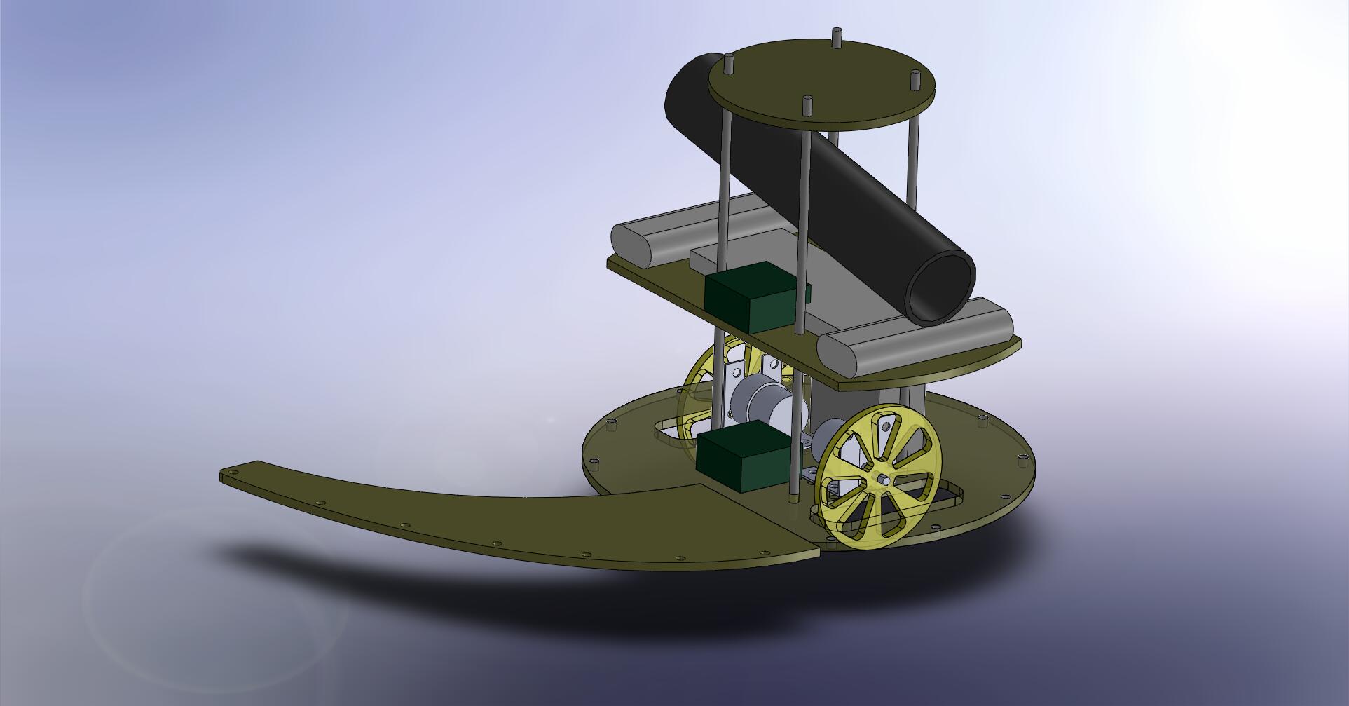
- CAD wheels, new base, and new platform. Figure out where breadboard, battery, and hbridges will go. done
- Assemble everything and test it on actual platform. Does our basic design (open-loop orientation, unfolding ski, perimeter tracing) beat the brick?
- Troubleshoot basic design (skis may need to be refined multiple times)
- Test faster motors. Which have better performance?
- Test various wheel sizes. What is the maximum speed we can achieve?
- Consider optional improvements - light sensor? Limit switches for orientation? using meeasuring tape extensions for crab walking? ball launcher?
- Find max Ruler extension such that it will snap back when constrained by floor. Max is 36inches
- Find time extension at 5 V of ruler (Done 3 secs to)
- Many things require 5 V only. maybe make on rail 5 V (Done)
- Make sensitive yet robust end switch for ruler
- Back up project code (Done feb 21)
- PUt off switch for solenoids
- CAD up base, wheels, guid (done)
- code tape extender
- try out new motors.
- Ball spewer. Best to have a door because it can be used to extend over. It must be flexible enough to run into bumper!-
- try out new wheels
Meeting Notes
- Feb 18:
- * court start is mirror image -> can always start moving counterclockwise * Court start is mirror image -> can always start moving counterclockwise *
- Maybe keep design open enough to allow shooting opponent
- Feb 19: c32 screw specs EricLew 2/20/09 screws are 4-40 or 6-32 according to Matt and Melody. dimensions for center-to-center distance are about 3 5/8" x 2 1/2" - need to redo these with calipers
- Sn754410 screw specs ESL 2/29 center-to-center about 1 11/16" redo with calipers
- Battery specs ESL 2/20 Length 5 1/8" Width 1 13/16" Height 29/32"
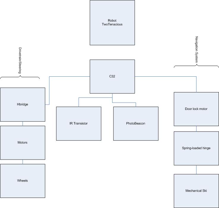
System Block Diagram
- block diagram:
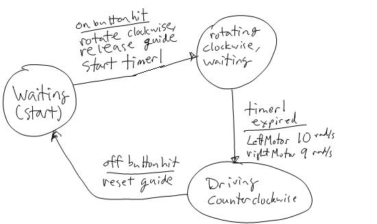
State Diagram
Purchases
| Item | Cost | Purchaser |
| Rollerblade | 15.00 | Sam |
| Masonite | 8.00 | SAm |
| Door lock motor | 5.25 | Sam |
| switch | 1.25 | Sam |
| Two Jameco 161382 motors | 36.00 | Al |
| Door lockmotor | 5.25 | Al |
| Switches (6), fuse holder, fuses (2),battery connectors (2), Tape sensor | 15.30 | Al |
| M3-10 screws (5) and 1/4-20 locknuts (9) | 3.96 | Al |
| Fasteners + hinges + autotape | 58.00 | Al |
| 2 164786 Motors RETURNED | -54.00 | Al |
| Molex connectors | 2.00 | Eric |
| Molex connectors | 0.20 | Al |
| Fuses | 1.00 | sam |
| hardware fasteners nuts, etc | 8.90 | sam |
| wheels | 10.81 | sam |
| acrylic | 4.33 | sam |
Optional Shooting Module
If we have time ( a big if) maybe we can add a shooting mechanism. THIS SHOULD ONLY BE PURSUED IF WE HAVE TIME AND IF IT DOESN'T HURT SPEED DETRIMENTALLY. I envision a shooter fixed to the right side of the craft. An IR sensor stuck in a tube (to decrease its cone of detection) onthe right is the sensor to fire. When it sees the oponnent,we shoot. After a certain time after seeing the opponent, it turns off, letting more power go to wheels. A similar IR + tube on the left will turn the motor on (IR mounted on the opposite side). Another great idea is to just shoot all the balls at the beginning. When we are spinning around to orient ourselves correctly, we will also be searching for the opponent. If we see them, then shoot!!Motor Calculations
We measured the stall current to be 1.2A and the motor resistance to be 10ohms. From the information from Jameco's web, we know all the terms for the following motor equation at maximum efficiency: V = IR+Ke*w V = 12v I = 293mA R = 10ohms w = 145RPM Solving, Ke = .0626 V/RPM We can also solve for Kt = T/I, at maximum efficiency Kt = 2900g*cm/A| Torque @ Max. Efficiency (g-cm) | 850 |
| Operating Range (VDC) | 4.5-12 |
| Current @ Max. Efficiency (mA) | 293 |
| Gear Case Size (Diameter x Length) (inch) | 1.3 x 0.9 |
| Gear Ratio | 30:1 |
| Motor Size (Diameter x Length) (inch) | 1.4 x 0.7 |
| Shaft Size (Diameter x Length) (inch) | 0.23 x 0.90 |
| Rated Voltage (VDC) | 12 |
| Terminal Type | Solder |
| Speed @ Max. Efficiency (RPM) | 145 |
Minimum Speed Calculations
Circuits
ThisLink -- ESL 2/20 Pin choices for c32 (wheel) Hbridge C32 J1 1 ground -> 2 Adir -> T5 3 Aen -> T0 4 Bdir -> T6 5 Ben -> T1 6 ground (doorlock/optional launcher hbridge) c32 J1 1 ground -> 2 Adir -> M0 3 Aen -> M1 4 Bdir -> M2 5 Ben -> M3 6 ground phototransistor vout -> AD0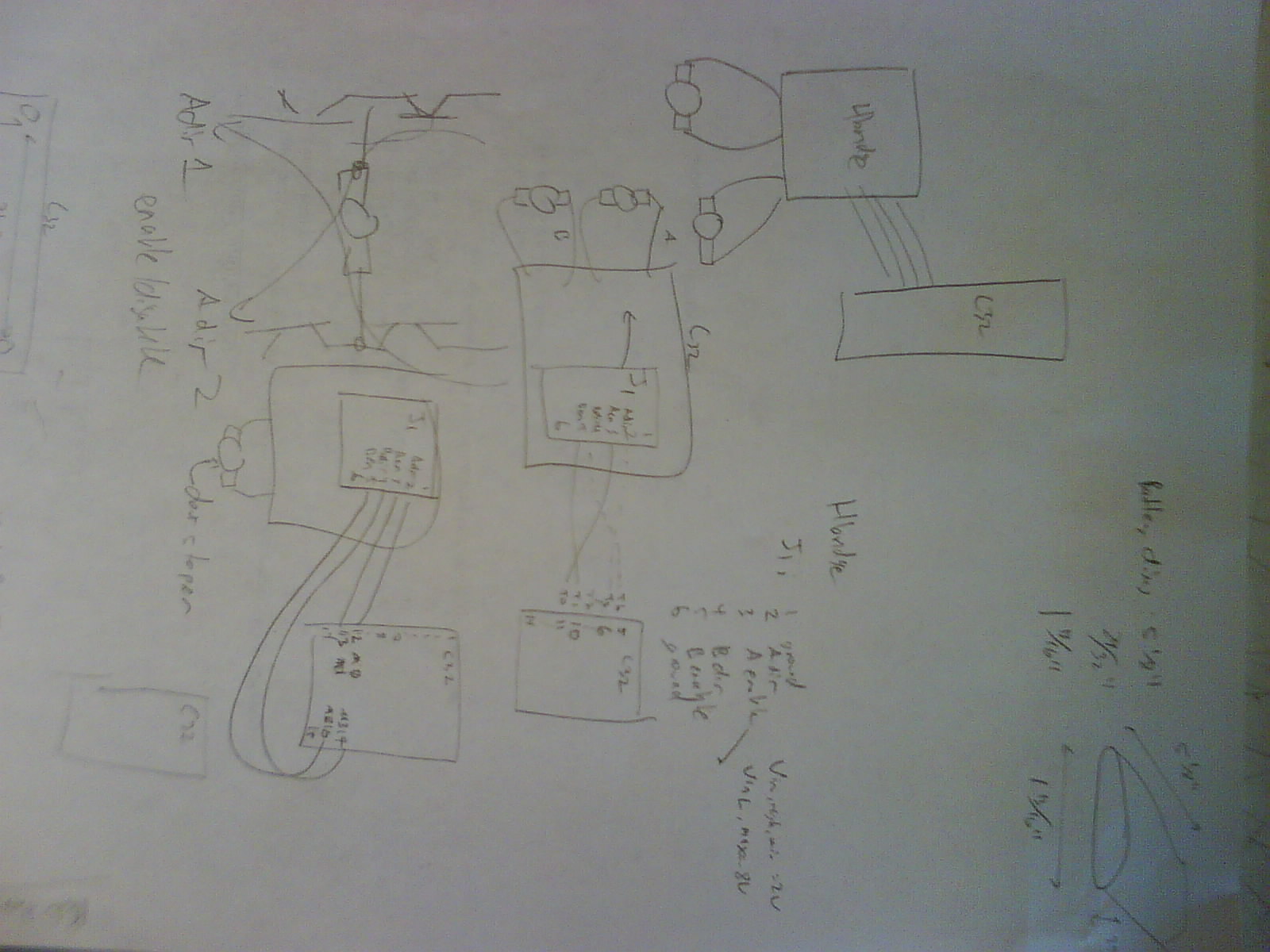 This photo is way too dark!
Beacon sensing circuit:
This photo is way too dark!
Beacon sensing circuit:
Inventory
3x 2ft long 1/4" -20 all-thread 2x 161382 1x awesome plexiglass base plate 1x doorstop motor 4x rollerblade wheels 1e5x fasteners 5x limit switches 1x fuse (why?) 10x bearings 6x lbracketsMeasurements
| Item | w | l | d |
| ball | 1.75 " dia | ||
| 754410 | 2" | 2" | 1" |
| C32 | 4" | 3" | 1.5 |
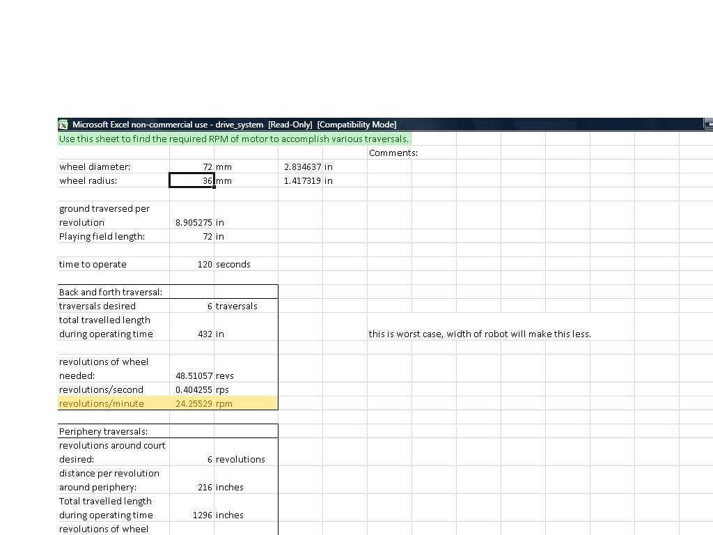
- drive_system.xls: updated with 72mm wheel diameter
PrototypeOne (<- check it out by clicking on link)
External Links
http://www.stanford.edu/~egangans/Robot/Driving.htm- beacon sensing circuit diagram:
Timers Allocation
Timer 0-3 for eric (door lock, light sensor, drive motors) Timer 4-5: tape measure extensionNotes
Masonite - 24" x 48" for lasercam on one sheet: 1 bottom plate two skis second level 6" top plate wheels (mostly 72mm, maybe a set of 4in). on both acrylic sheet and masonite extra hubs- twotenacious.zip: TWOTENACIOUSCODE
Ideas, requests, problems regarding TWiki? Send feedback