new web: http://bdml.stanford.edu/pmwiki
TWiki > Rise Web>TWikiUsers > JonathanKarpick>OneDOFClimber (26 Aug 2005, JonathanKarpick)
-- JonathanKarpick - 25 Aug 2005
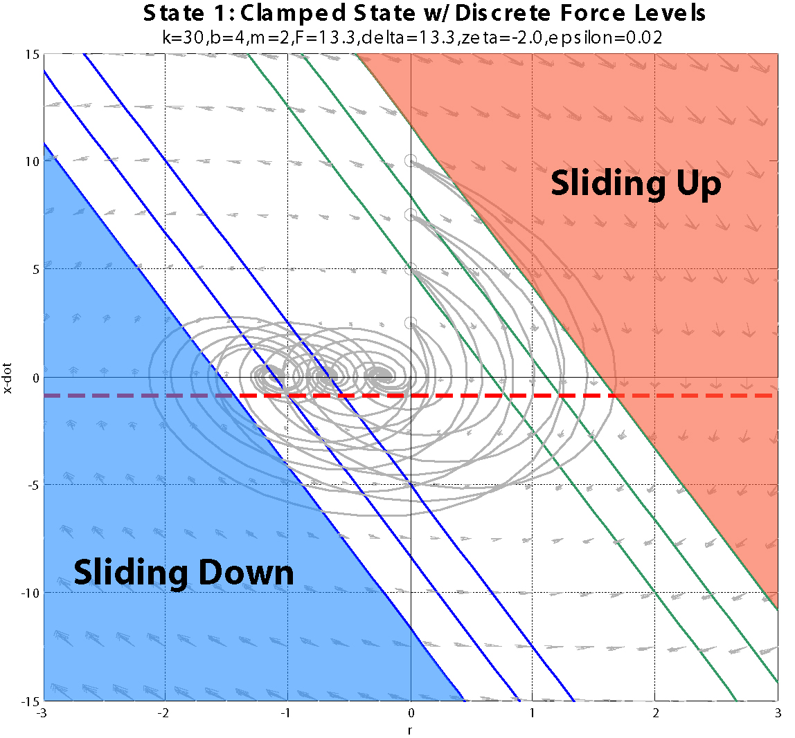
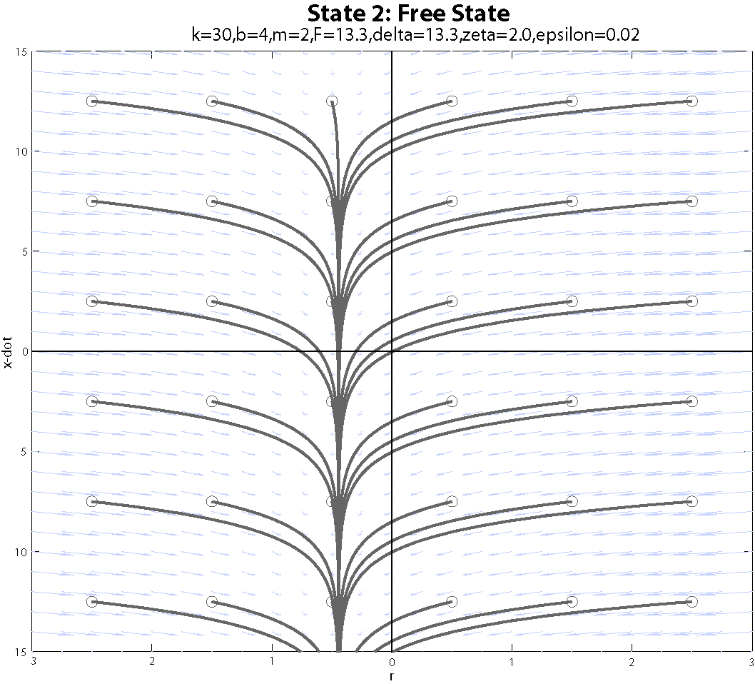
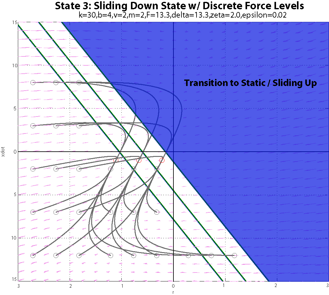
Added velocity-dependant (viscous) friction into the model. Coming back to determining trajectories (aka control strategies) led me to the following evolving process which would have to be done for each set of robot characteristics:
 -- JonathanKarpick - 17 Jun 2005
OneDimClimberNotes.pdf: Updated with quasi-static climbing
-- JonathanKarpick - 27 May 2005
Some drawings and a plot of an example trajectory that uses the mass to add and control energy in the system and get the foot moving up the pole:
OneDimClimber-QtrReport.ppt:
-- JonathanKarpick - 13 May 2005
I've been working on a semi-formal write-up of this model for distribution. The current version is attached here:
OneDimClimberNotes.pdf
I still have some thinking to do about transitioning from sliding to clamped and then tying trajectories together for a closed cycle. And of course, how everything ties together to foot height, since that's the object of the whole thing.
-- JonathanKarpick - 06 May 2005
Quick chat with Dan Santos after today's RiSE Telecon led to some good questions:
  (or maximum
  depending upon your point of view) which puts on a condition on the entrance to the Free state to begin with...
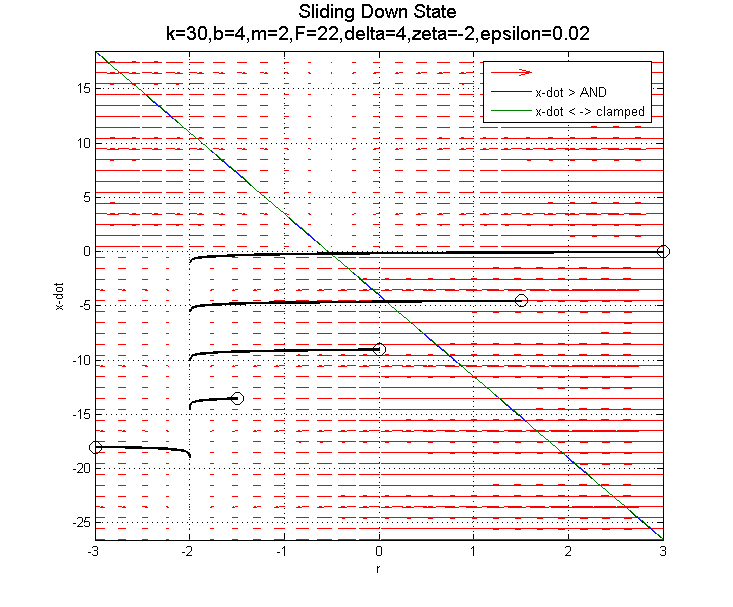
Also, the Sliding Down state will likely use a positive force application to keep the steady state spring length near zero.
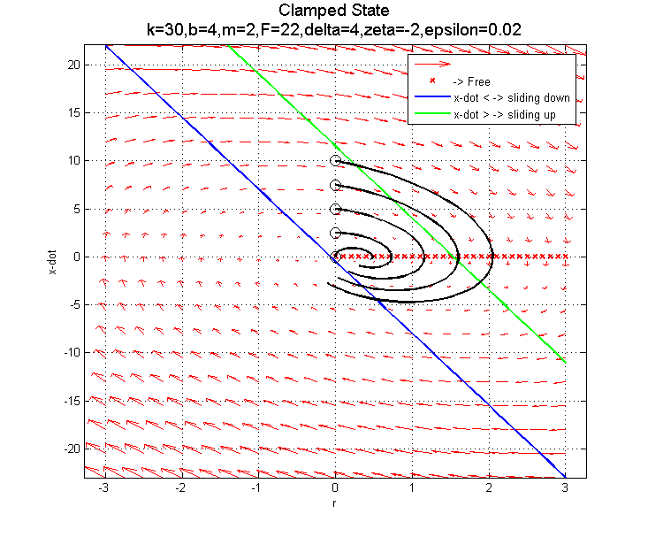
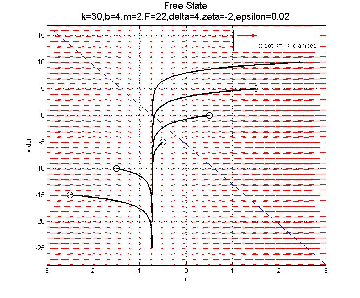
The goal becomes how to switch among the following phase portraits such that the climber actually moves up the pole.
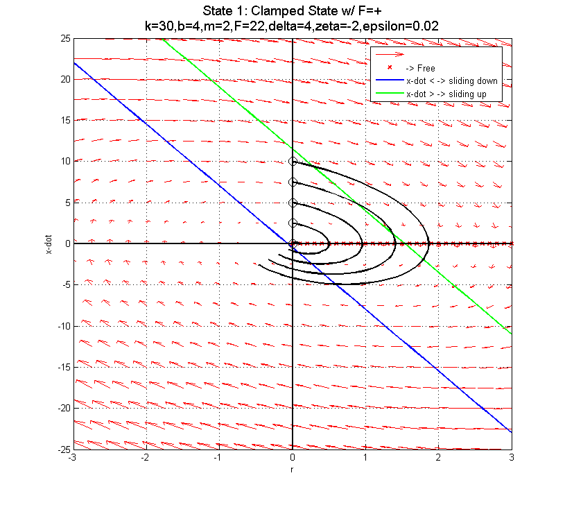
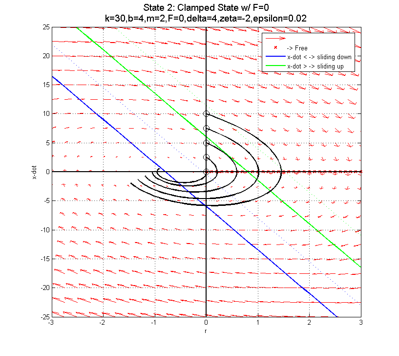
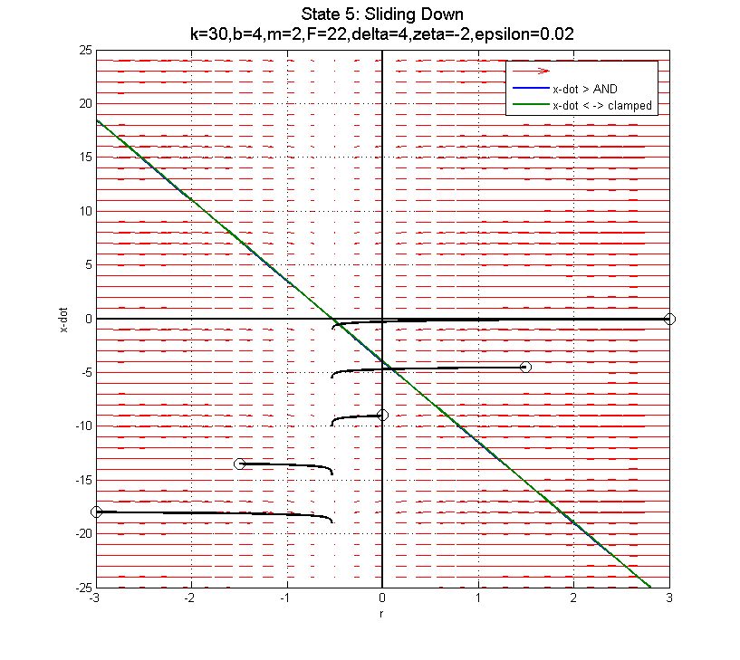
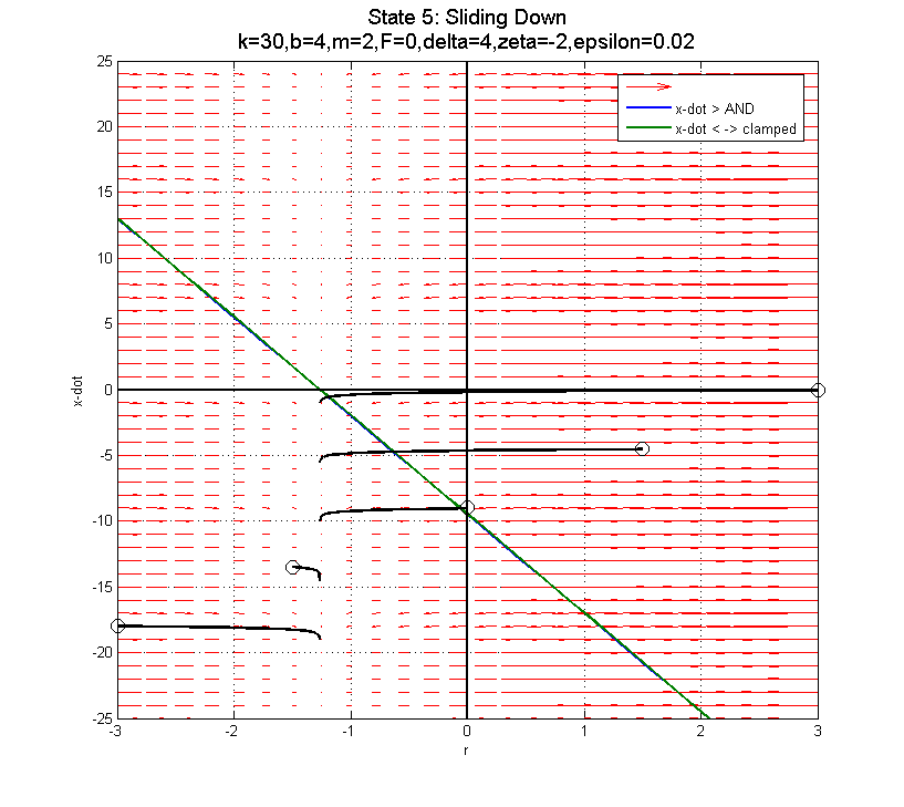
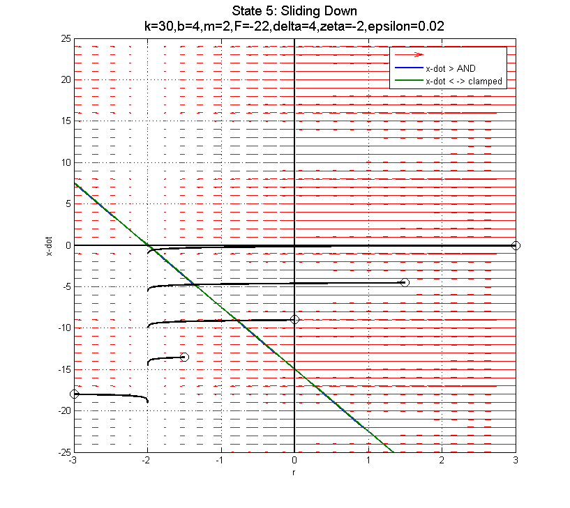
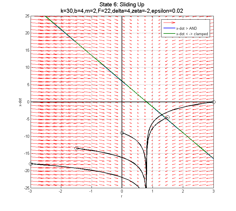
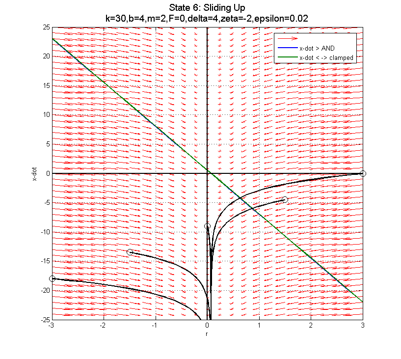
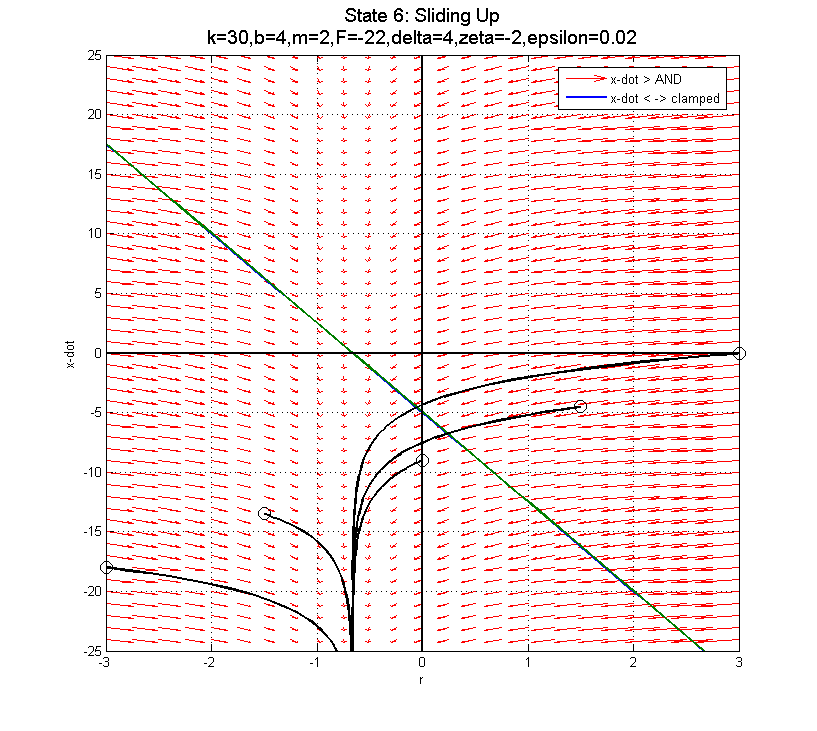
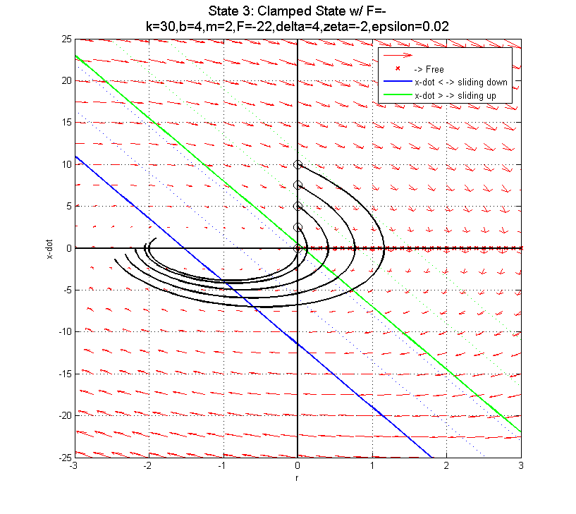 In the clamped state, transitioning from F=22 to F=0 to F=-22 as you near the sliding down boundary (for x-dot < 0) doesn't appear to do much good... The blue line is the transition from clamped to sliding down. The green line is the transition from clamped to sliding up.
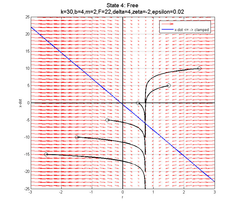
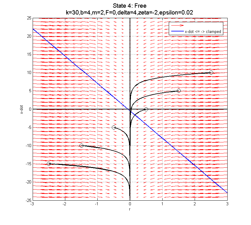
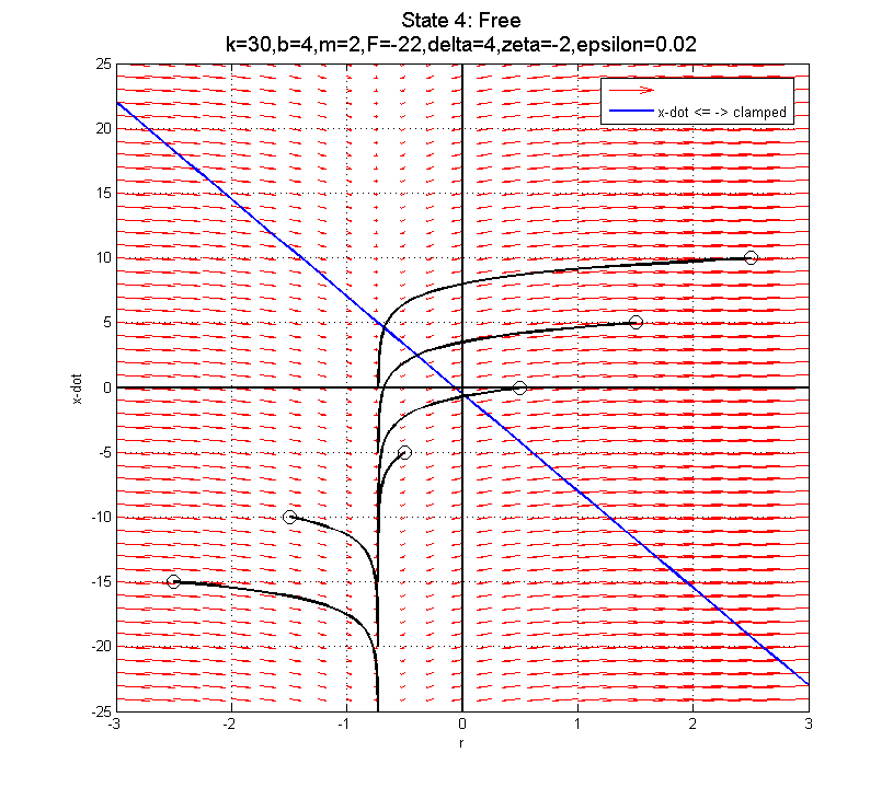 Using F=-22 (negative) is probably best, since it pushes you into the better part of the clamped phase plot for after the clamp... The blue line depicts the transition from clamped to sliding down when F=22. In fact, there is a specific curve for each of these plots which separates trajectories that will work in the clamped state from those that won't (assuming you transition at the blue line). The boundary trajectory can be found by locating the point along the blue line where (in the clamped state):
  and then following the trajectory in the free state that intersects this point. Transitions into the Free state above this trajectory can be successfully re-clamped, while those that transition below this trajectory will end up sliding down...
For this configuration, that end-point on the blue line is
  ,
,  for clamped state with F=22N.
 -- JonathanKarpick - 28 Apr 2005
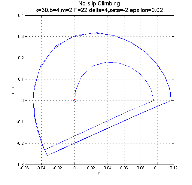
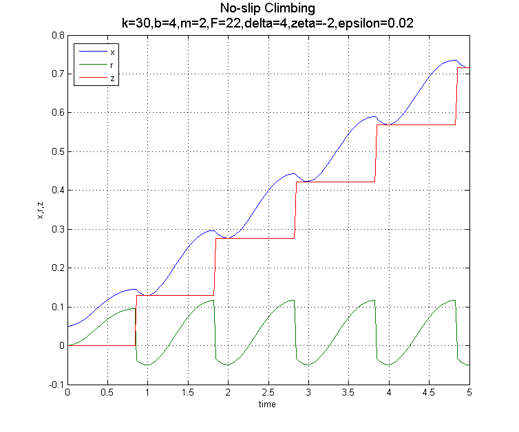
In order to have trajectories without any slipping, the transition from free to clamped must occur before a transition to clamped would cause slipping (i.e., before the mass is falling too quickly...) This can be done by re-clamping when
  A sample trajectory and z time history are shown here:
 -- JonathanKarpick - 22 Apr 2005
State Phase Portraits and Transitions:
 Transition to sliding down:
  Transition to sliding up:
  Transition to free:
  AND
AND 
 Transition to clamped:
 -- JonathanKarpick - 18 Apr 2005
Note: a PDF version of this page is attached here: OneDOFClimberNotes.pdf - the equations are a little cleaner in the PDF file.
The one degree-of-freedom climber is an example cooked up between myself, Mark, and Dan Santos about what a really simple climber could look like:
The climber consists of a body connected to a (mass-less) foot via a spring, damper, and force actuator in parallel. The foot can clamp onto a vertical pole with a given clamping (normal) force, or release the pole. Gravity acts down the pole:
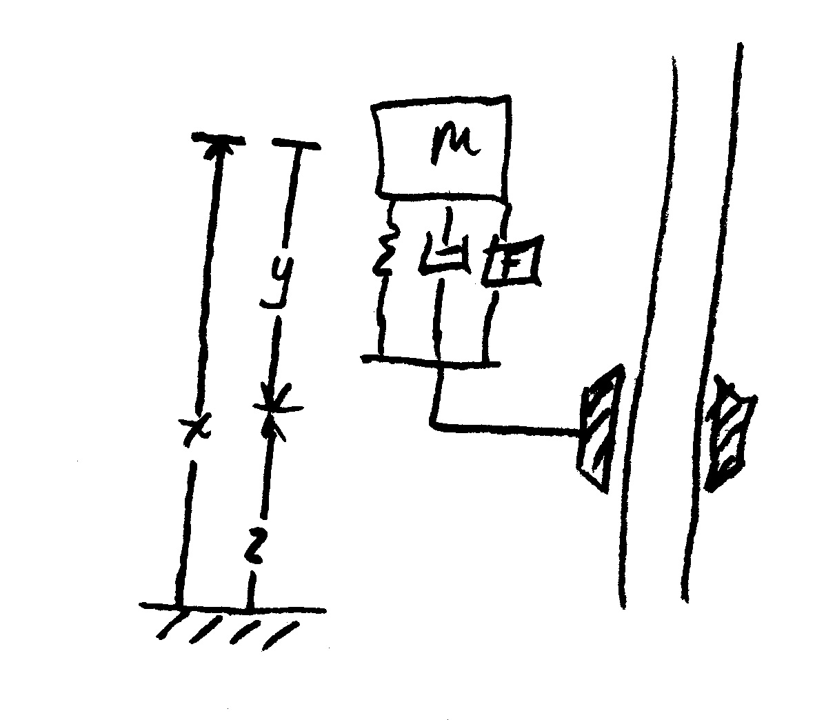 There is Coulumb friction between the clamp and the pole when the climber has clamped the pole. The static friction limit is slightly more than the weight of the climber

 and the kinetic friction force generated when sliding is slightly less than the weight of the climber

 Variables:
 - absolute coordinate of the body
 - relative coordinate from body to foot
 - uncompressed length of spring
 - absolute coordinate of the foot,
 - amount of spring extension,
 - mass of climber
 - gravity
 - actuator force
 - wall force applied to foot (friction force)
 - spring constant
 - damping constant
Equations when clamped and not sliding:


 Equations when not clamped:


 Equations when sliding down:


 Equations when sliding up:


 Transitions:
From clamped to free when and
and  , set
, set  (retract foot)
From clamped to sliding down when , set
, set  ,
,  (give foot a small downward velocity), and
  (try to make
  positive)
From clamped to sliding up when , set
, set  ,
,  (give foot a small downward velocity), and
  (retract foot)
From free to clamped when , set
, set  ,
,  , and
, and  (extend foot)
From sliding down to clamped when , set
, set  and
and  (extend foot)
From sliding up to clamped when , set
, set  and
and  (extend foot)
Some observations:
 to prevent sliding when you apply the force when the entire system is at rest.
The force applications given above for each state are intended in all cases to get (or keep) the foot moving up the pole. To do:
- Generate phase plots (over a range of forces) for each state: foot static, falling, foot sliding down, and foot sliding up. Make sure that transition boundaries are depicted.
- Choose trajetory/control strategy that goes (at least) from static to falling and back - check to ensure that the 'bot is actually climbing.
- Optimize?? Somehow...
- Look for limits - i.e., how far can it go in one state and still transition to another state to generate a "closed" (i.e., repeatable) trajetory.
- Is there a way to determine stability of a trajectory?
- Static
 Free
Free  Static
- Static
 Free
Free  Sliding Down
  Static
- Static
 Sliding Down
  Free
Free  Static
- Static
 Free
Free  Sliding Up
  Static
- Sliding Down
 Free
Free  Sliding Down
- etc - the only requirement is that each trajectory include the free state... (or maybe sliding up...)
   k = 30;  %N/m  - Spring constant
   b = 4;   %N-s/m - Damping constant
   neu = 2; %N-s/m - Viscous friction constant
   yn = 5;  %m - Spring natural length
   m = 2;   %kg
   g = 10;  %m/s^2
   delta = 2*m*g/3; %Static Friction = mg+delta
   zeta = -m*g/10;%Dynamic Friction = mg+zeta
   epsilon = m*g/1000;  %Karnopp friction deadband level
   Flevel = delta;  %N
   Fs = m*g+delta;
   Fd = m*g+zeta;
Phase plots:


 -- JonathanKarpick - 17 Jun 2005
OneDimClimberNotes.pdf: Updated with quasi-static climbing
-- JonathanKarpick - 27 May 2005
Some drawings and a plot of an example trajectory that uses the mass to add and control energy in the system and get the foot moving up the pole:
OneDimClimber-QtrReport.ppt:
-- JonathanKarpick - 13 May 2005
I've been working on a semi-formal write-up of this model for distribution. The current version is attached here:
OneDimClimberNotes.pdf
I still have some thinking to do about transitioning from sliding to clamped and then tying trajectories together for a closed cycle. And of course, how everything ties together to foot height, since that's the object of the whole thing.
-- JonathanKarpick - 06 May 2005
Quick chat with Dan Santos after today's RiSE Telecon led to some good questions:
 - Is there ever a time when you can actually stop the climber from sliding down the pole once it starts?
- From calculations yesterday, the transition from free to clamped can only work when the velocity of the mass is less than a certain level (
 to be exact) - WHICH DOESN'T DEPEND ON THE FORCE APPLIED and the spring extension is less than a certain level (which does depend on the force:
  )
)
- For a transition from sliding down to clamped to work, it must occur at a point that meets the same conditions.
- Actually, those equations are only sufficient, because I am assuming that the transition from Free to Clamped occurs on the Clamped-to-Sliding Down boundary. If the transition occurs off of this boundary, the criteria is that the resulting trajectory cannot cross the boundary.
- From calculations yesterday, the transition from free to clamped can only work when the velocity of the mass is less than a certain level (
- What are the boundary cases?
- What are the restrictions on the relations between m, k, b, Fs, F, Fd for different boundary cases or climbing methods?
 (or maximum
  depending upon your point of view) which puts on a condition on the entrance to the Free state to begin with...
Also, the Sliding Down state will likely use a positive force application to keep the steady state spring length near zero.
The goal becomes how to switch among the following phase portraits such that the climber actually moves up the pole.


 In the clamped state, transitioning from F=22 to F=0 to F=-22 as you near the sliding down boundary (for x-dot < 0) doesn't appear to do much good... The blue line is the transition from clamped to sliding down. The green line is the transition from clamped to sliding up.


 Using F=-22 (negative) is probably best, since it pushes you into the better part of the clamped phase plot for after the clamp... The blue line depicts the transition from clamped to sliding down when F=22. In fact, there is a specific curve for each of these plots which separates trajectories that will work in the clamped state from those that won't (assuming you transition at the blue line). The boundary trajectory can be found by locating the point along the blue line where (in the clamped state):
  and then following the trajectory in the free state that intersects this point. Transitions into the Free state above this trajectory can be successfully re-clamped, while those that transition below this trajectory will end up sliding down...
For this configuration, that end-point on the blue line is
  ,
,  for clamped state with F=22N.


 -- JonathanKarpick - 28 Apr 2005
In order to have trajectories without any slipping, the transition from free to clamped must occur before a transition to clamped would cause slipping (i.e., before the mass is falling too quickly...) This can be done by re-clamping when
  A sample trajectory and z time history are shown here:

 -- JonathanKarpick - 22 Apr 2005
State Phase Portraits and Transitions:
 Transition to sliding down:
  Transition to sliding up:
  Transition to free:
  AND
AND 
 Transition to clamped:
 -- JonathanKarpick - 18 Apr 2005
Note: a PDF version of this page is attached here: OneDOFClimberNotes.pdf - the equations are a little cleaner in the PDF file.
The one degree-of-freedom climber is an example cooked up between myself, Mark, and Dan Santos about what a really simple climber could look like:
The climber consists of a body connected to a (mass-less) foot via a spring, damper, and force actuator in parallel. The foot can clamp onto a vertical pole with a given clamping (normal) force, or release the pole. Gravity acts down the pole:
 There is Coulumb friction between the clamp and the pole when the climber has clamped the pole. The static friction limit is slightly more than the weight of the climber

 and the kinetic friction force generated when sliding is slightly less than the weight of the climber

 Variables:
 - absolute coordinate of the body
  - relative coordinate from body to foot
  - uncompressed length of spring
  - absolute coordinate of the foot,
 - amount of spring extension,
 - mass of climber
  - gravity
  - actuator force
  - wall force applied to foot (friction force)
  - spring constant
  - damping constant
Equations when clamped and not sliding:


 Equations when not clamped:


 Equations when sliding down:


 Equations when sliding up:


 Transitions:
From clamped to free when
 and
and  , set
, set  (retract foot)
From clamped to sliding down when
 , set
, set  ,
,  (give foot a small downward velocity), and
  (try to make
  positive)
From clamped to sliding up when
 , set
, set  ,
,  (give foot a small downward velocity), and
  (retract foot)
From free to clamped when
 , set
, set  ,
,  , and
, and  (extend foot)
 From sliding down to clamped when
 , set
, set  and
and  (extend foot)
 From sliding up to clamped when
 , set
, set  and
and  (extend foot)
Some observations:
 to prevent sliding when you apply the force when the entire system is at rest.
The force applications given above for each state are intended in all cases to get (or keep) the foot moving up the pole. To do:
- Put up some drawings in here
- Simulate a system with no friction limit and look at trajectories (use Matlab's LMI??)
- Simulate system with friction limits and look at trajectories
Ideas, requests, problems regarding TWiki? Send feedback