new web: http://bdml.stanford.edu/pmwiki
TWiki > Manufacturing Web>ManufacturingHome > SDMOverviewAndLinks>UnigraphicsTutorial (31 Jul 2010, DanAukes)
Basic Unigraphics Tutorial
for Shape Deposition Manufacturing. This covers the Planar Mill operation for flat parts. Also see UnigraphicsQuickReference for a quick refresher Contents:Toolpath Planning Instructions for UG V18.0
Important Note about Unigraphics: Unigraphics is extremely fussy with file names and locations; absolutely no spaces are allowed in the file name or anywhere in the path of that file! Everybody gets caught by this at some point! For example, putting a file in My Documents or on the desktop will result in errors because: "C:\Documents and Settings\username\folder\Desktop" HAS SPACES IN THE PATH!!This also goes for any files used along the way, such as "haas2.mdfa", these must have a "legal" pathname.
I think it also may not allow either "-"s in the path, or having a path that is more than ~6 subdirectories deep.
Preparing Your Solidworks Part
These instructions allow you to prepare your part in Solidworks.- Open file named wax_block_12inch.sldprt. This file can be found in numerous folders (You can find it in \\Chewie\sphan).
- Wax_Block_12inch_2006SP4_1.SLDPRT: Wax Block file for SolidWorks 2006 SP 4.1
- Open your Solidworks part
- Click new->assembly
- Click Insert -> Component-> existing Part/Assembly
- Click on Wax_Block_12inch, hit OK
- Insert your Solidworks part
- Click Mate Components
- Click on the top surfaces of the mold and part. The coincident mate should be highlighted. Hit OK
- Move your part around to the appropriate place on the wax block
- Save the file
- Highlight the wax block
- Click Edit Part
- Highlight part that becomes cavity
- Click Insert-> Mold -> Cavity
- Uncheck edit components
- Save
- Open the wax block
- Save as Step 203 file.
Getting Started
- Build your part in SolidEdge or SolidWorks. Export your part file as a STEP203 file so that it can be used in Unigraphics (UG). Rename the extension from .STEP to .STP. When using Solidworks, you will often use an assembly to create your mold part. Make sure you export the mold part file and not the assembly file!
- Open a new part file in UG and make sure you select metric units (mm). Import your part file (from file menu) as a STEP203 file. You will get a warning that your file is in English units if you originally set it up that way.
- Under applications menu, select manufacturing. Select cam_general from the top list and mill_planar from the bottom list, and check initialize. This will bring up a new window named Operation Navigator.
Types of Operations
Available types of operations:- Planar Mill.
- Cavity Mill
- Contour Area
- Making an Extraction toolpath is a type of Planar Mill operation, but it is a little different and is explained below in its own category.
Creating a Planar Mill Operation
|
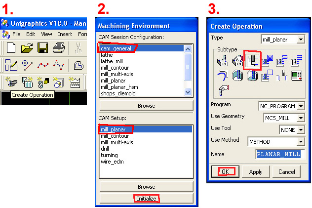
1. Click on "Create Operation". 2. In the "Machining Environment" window that pops up, select "cam_general" in the top window and "mill_planar" in the bottom window. 3. In the "Create Operation" window, select the "PLANAR_MILL" button (top, third from left). |
|
|
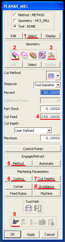
This is the main window. You'll have to do a lot of stuff here. Do the things in this order, explained below. In summary, these are:
1. Select the dimensions of the mill bit you'll use. See below for a screenshot of the window that pops up and additional explanation. 2. Under "Geometry", click on the left-most button named Part and then click on Select below it. (a) If you have a single depth, click on just the top surface of your part (top surface of the wax block). (b) If you have multiple depths, choose the top of the wax block and every lower surface including the bottom surface of your part and any "islands" and then exit. 3. Again, under Geometry, click on the right-most button named Floor and then click on Select below it. Click on your bottom-most deepest surface (face) of your part and then exit. 4. Enter the feed rate here. This can be found in the Tool Table. For the next several buttons you have to press, there are screenshots below of the windows that pop up. 5. In Method, set the Initial Engage, Internal Engage, Final Retract, and Internal Retract all to 'Tool Axis'. This forces the tool to come straight down instead of a much slower spiral approach. 6. In Cutting, change the "Cut Order" to "Depth First" instead of "Level First". 7. In Cut Depths, you set how deep you want the mill to go on each pass (the numbers are found in the Tool Table). Set the Initial, Maximum to the number in the table, you can leave Final and Minimum at 0. 8. In Avoidance, set the Clearance Plane to 10mm so the mill moves back and forth high above the surface of the wax block. Click on: "Avoidance" -> "Clearance Plane" -> "Specify". Type "10" in the box and click OK. Then, you should ALWAYS click on 'Display' in this sub-window to display the clearance plane--it will display a triangle which you should verify is the appropriate distance above the wax block. 9. Finally, you click the "Generate" button to make the new toolpath. |
Screenshots of the different menus:
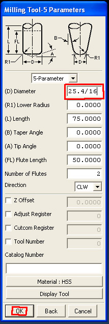
| 1. Select Mill Bit: Look at the Tool Table to see the options for what mill bits we have available to use. In the first window that pops up (not shown here), enter the name of the mill bit, just for your own reference. e.g. put MILL5 for the 5th tool in the HAAS, which is 1/16". Then enter the diameter of the tool in the Diameter box, in [mm]. You can easily convert to [mm] by typing 25.4 * {tool diameter in inches}, e.g. 25.4/16 to convert 1/16" to [mm]. Also, be sure to check that the actual mill bit you will be using is long enough to fit into the deepest hole in your part! |
|
||||||||||
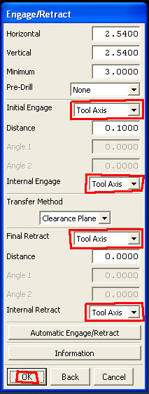
| 5. Method Engage/Retract: Here we choose "Tool Axis" so it goes straight up and down rather than going on a long spiral path which takes a long time (but makes a better surface finish, I guess). |
|
||||||||||
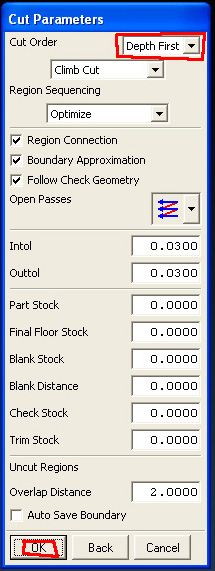
| 6. Cutting: Choose "Depth First" which means it will cut all levels in one hole in the wax block before proceeding to the next hole. It's faster than "Level First" which will cut all the parts at the first depth (e.g. 1mm), then all the parts at the second depth (e.g. 2mm), etc. |
|
||||||||||
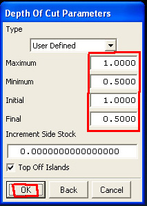
7. Cut Depths:
This is how deep the mill will go each pass. Put the Maximum and Initial to the value in the Tool Table. Usually you also put the Minimum and Final to half this value. Leaving Minimum = 0 and Final = 0 is also ok. For Initial, if you know that your part has a depth that is less than the value in the table, set the value to the depth of your part (e.g. your part has a very shallow groove of depth 0.6, and the value in the table is 1.0, set Initial to 0.6).
Handy reference table:
|
|
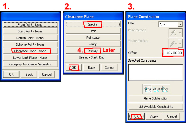
| 8. Clearance Plane: The clearance plane is the height at which the mill is at when it moves back and forth over the block going from one place to another. It is VERY important you do this correctly or it will break your mill bit or mess up your part! Click on the buttons in steps 1 and 2. In step 3 type 10 (for 10mm) in the box and click ok. In step 4, click the "Display" button and verify that it displays a little plane the correct distance above your part. Note that if you made your Unigraphics part in [inches] instead of [mm] the clearance plane will be way too high above the block, and you need to start over with a part in [mm]. |
|
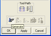
9. Generate Toolpath:
Now you can generate your tool path. There are two ways of doing this:
|
OR 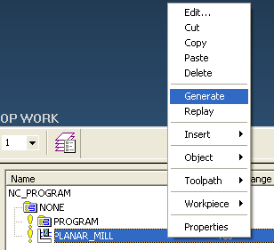
|
Verifying your toolpath
- Red: Rapid Movements
- Yellow: Engage/Retract
- Blue: Cuts within the block
l You can watch a virtual tool run through your toolpath: rightclick on the icon representing your toolpath and select "Toolpath>Verify"
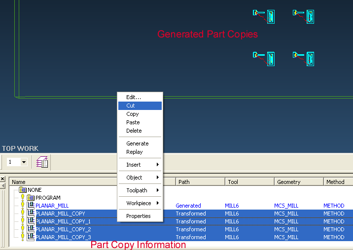
Making multiple copies of the toolpath
In order to generate multiple copies of your part on one block of wax, right-click on Planar_mill in the operation navigator window at the bottom of the screen and selectObject -> Transform -> Rectangular array.
If you have used the "official" wax block which has the origin correctly set up, the first two boxes that show up will contain all zeros and you should just click "Ok" for both. If you didn't use the official wax block, you should because it is just much simpler. But you can still proceed:
- For the first box that shows up, enter where you want to map from your original part i.e. from the origin.
- For the second box that shows up afterwards (looks exactly the same as the first), choose where you want to start your array. Remember that XC and YC are relative to your current origin.
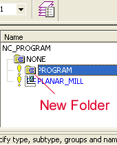
Now make a new folder, or "Program Group", by right clicking on the Program folder, then Insert -> Program Group .
 Then, select all the transformed parts you just made (don't select the original one). Right-click -> "Cut". Then right-click on the new Program Group you just made and "Paste Inside".
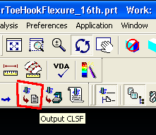
Postprocessing the toolpath
| Now you will begin the process of exporting your toolpath into a format the Haas mill can understand. Select the new project folder holding all your parts to highlight it, and then select Output CLSF from the button bar (shown to the right). In the Output CLSF window, uncheck "List Output" and leave the file name the same as what is filled in. Also leave it as CLSF standard. Check off the box next to program. Hit OK. |
|
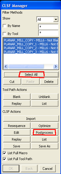
| Now, go to the Tools menu -> CLSF. Select the CLSF file you just made. The CLSF Manager window will pop up (shown to the right). In the CLSF Manager, Click on Select All from CLSF manager, click on Postprocess. In the NC Postprocessing window that pops up, under MDF Name, choose Specify and select the "haas2.mdfa" file (attached here, haas2.mdfa). Click on Postprocess in that window. UG will now churn the code for you a black Graphics Postprocessor Module will show up. If you have small arcs in your design, you may generate errors which you can ignore. (Note: For all other errors in this step, see the note about Unigraphics file names at the top of this page). Click Yes to continue and save all files generated. |
|
- Open the .ptp file up in a text editor (Notepad). Delete the first two lines of the file after the %.
- Open up the Header and Footer text file (attached here, headerandfooter.txt).
- Copy and paste the header into the location where you just deleted the two lines. You then need to change two of the lines in the header to correspond to the correct tool that you are using. i.e. if you are using 1/8 tool i.e. MILL_4, make sure that on line 5 of the header you have T4 and on line 9 of the header you have H4.
- Copy and paste the footer at the very end of the file.
Tool Table
The tool table can be found at: HAASToolTableLinks to Advanced Things:
CombiningPtpFiles - Cutting and Pasting ptp files -- if you want it to machine things faster. MachiningOnTheHAAS - Machining on the HAAS in the RPL Making an Extraction Toolpath -- make a link to thisIdeas, requests, problems regarding TWiki? Send feedback