new web: http://bdml.stanford.edu/pmwiki
TWiki > Manufacturing Web>ManufacturingHome > SDMOverviewAndLinks>SDMTutorialNotes (31 Jul 2010, DanAukes)
Shape Deposition Manufacturing Tutorial
Original Document Compiled by EmilyMa and MiguelPiedrahita (10-16-03). Revised extensively by Miguel, with significant input from AlanAsbeck and others. Contents:- Toolpath Planning Instructions for UG V18.0
- Preparing Your Solidworks Part
- Getting Started
- Table of Tools ACTUALLY on Haas as of July 13, 2007
- Table of Info for Tools
- Which Type of Operation to Use?
- Creating a Cavity_Mill Operation
- Creating a Contour_Area Operation
- Creating a Planar Mill Operation
- Making multiple copies of the toolpath
- Verifying your toolpath
- Postprocessing the toolpath
- Combining ptp Files
- Machining on the HAAS in the RPL
- Casting Urethane
- how to define "trim" area for milling operation in unigraphics
Toolpath Planning Instructions for UG V18.0
Important Note about Unigraphics: Unigraphics is extremely fussy with file names and locations; absolutely no spaces are allowed in the file name or anywhere in the path of that file! Everybody gets caught by this at some point! For example, putting a file in My Documents or on the desktop will result in errors because: "C:\Documents and Settings\username\folder\Desktop" HAS SPACES IN THE PATH!!This also goes for any files used along the way, such as "haas2.mdfa", these must have a "legal" pathname.
I think it also may not allow either "-"s in the path, or having a path that is more than ~6 subdirectories deep.
Preparing Your Solidworks Part
These instructions allow you to prepare your part in Solidworks.- Open file named wax_block_12inch.sldprt. This file can be found in numerous folders (You can find it in \\Chewie\sphan).
- Wax_Block_12inch_2006SP4_1.SLDPRT: Wax Block file for SolidWorks 2006 SP 4.1
- Open your Solidworks part
- Click new->assembly
- Click Insert -> Component-> existing Part/Assembly
- Click on Wax_Block_12inch, hit OK
- Insert your Solidworks part
- Click Mate Components
- Click on the top surfaces of the mold and part. The coincident mate should be highlighted. Hit OK
- Move your part around to the appropriate place on the wax block
- Save the file
- Highlight the wax block
- Click Edit Part
- Highlight part that becomes cavity
- Click Insert-> Mold -> Cavity
- Uncheck edit components
- Save
- Open the wax block
- Save as Step 203 file.
Getting Started
- Build your part in SolidEdge or SolidWorks. Export your part file as a STEP203 file so that it can be used in Unigraphics (UG). Rename the extension from .STEP to .STP. When using Solidworks, you will often use an assembly to create your mold part. Make sure you export the mold part file and not the assembly file!
- Open a new part file in UG and make sure you select metric units (mm). Import your part file (from file menu) as a STEP203 file. You will get a warning that your file is in English units if you originally set it up that way.
- Under applications menu, select manufacturing. Select cam_general from the top list and mill_planar from the bottom list, and check initialize. This will bring up a new window named Operation Navigator. Check that the origin of your coordinate system is centered on the top surface of the block i.e. z starts at zero at top surface and points up, x and y start at zero from the middle of the block. If you need to move these values, go to WCS menu -> Origin.
- Check that you are in the Program Order View with the Operation Navigator open.
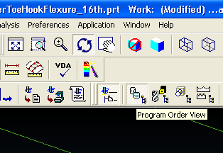
At this point, your WCS should match up with your MCS (manufacturing coordinate system). If they arent lined up, go to Geometry Tool View (two buttons to the right of Program Order View. In the Operation Navigator at the bottom of the screen, click on MCS_mill and move your coordinate system to match up with WCS. Then go back to Program Order View'.
Table of Tools ACTUALLY on Haas as of July 13, 2007
Note: Max cutting speeds are approximate and conservative, we should note successes with higher speeds--put them both here and in the Tool Info table below.All endmills are extended-length except where marked "short". In Unigraphics, where you set Cut Depths, set Initial, Maximum = maximum in table below. Set Minimum, Final to half of that number.
| Tool # | Tool Description | Tool Diameter (mm) |
Tool Reach (mm) |
Max Cutting Depth (mm) |
Max Cutting Speed, Wax (mm/min) |
Max Cutting Speed, Urethane (mm/min) |
|---|---|---|---|---|---|---|
| 1 | Face mill | N/A | N/A | 2 | 250 | 200 |
| 2 | empty | 4 | ||||
| 3 | 1/4 flat | 6.35 | ~40 | 3 | 1000 | 400 |
| 4 | 1/8 flat | 3.175 | ~25 | 2 | 250 | |
| 5 | 1/16 flat-short | 1.5875 | 6.35 | 1 | 1200 | |
| 6 | 1/16" (0.062") ball | 1.5875 | ~2 | 0.5 | ||
| 7 | Li's undercut tool | |||||
| 8 | 1/4" ball | 6.35 | ~40 | 3 | 600 | |
| 9 | 1/16 (0.062") long flat | 1.5875 | 21 | 1 | 150 | |
| 10 | 1/32" (0.031") long | 0.7938 | 7.781 | 0.5 | 250? | ?? |
| 11 | 0.015" flat-temporary | 0.381 | ||||
| 12 | 1/32 flat-short | 0.7938 | 2.38 | 0.5 | 500 | 500 |
| 15 | appears to be broken |
Table of Info for Tools
This table gives the general info (tool reach, max. cutting depth, etc.) for all the different tools we could potentially have in the HAAS. Don't change this except if you are able to run the tools at faster cutting speeds--in which case do update it so we can all run the tools faster!All tools are extended-reach except where indicated "short".
| Tool Description | Tool Reach (mm) | Max Cutting Depth (mm) | Max Cutting Speed, Wax (mm/min) | Max Cutting Speed, Urethane (mm/min) | Part Number |
|---|---|---|---|---|---|
| Face mill | N/A | 2 | 250 | 200 | |
| ½ flat | 4 | ||||
| ¼ flat | ~40 | 3 | 1000 | 400 | |
| 1/8 flat | ~25 | 2 | 250 | ||
| 1/16 flat (12mm) | 12 | 1 | 150? | ||
| 1/16 flat (21mm) | 21 | 1 | 150? | Harvey 13662 | |
| 1/32 flat | 10 | 0.5 | 250? | ?? | |
| 1/4" ball | ~40 | 3 | 600 | ||
| 1/8 ball | ~25 | 2 | 200 | ||
| 1/16 ball | ~12 | 1 | 100 | Harvey 36062 | |
| 1/32 ball | 0.5 | 50 | |||
| 1/16 flat-short | 6.35 | 1 | 1200 | ||
| 1/32" flat-short | 2.38 | 0.5 | 500 | 500 | |
| 0.015"flat |
Which Type of Operation to Use?
Available types of operations:- Planar Mill.
- Cavity Mill
- Contour Area
- Making an Extraction toolpath is a type of Planar Mill operation, but it is a little different and is explained below in its own category.
- If your part consists only of planar surfaces, use Planar Mill.
- If your part has curved or angled (in the Z-direction) surfaces, you have to use Cavity Mill to remove most of the material, AND THEN you ALSO have to use a Contour Area operation afterwards to smooth out the walls.
Planar Mill
- Similar to a laser cut - it looks straight down at your wax block and cuts out outlines. However, unlike a laser cut, it can control how deep the tool goes
- Always use this if your part consists only of planar surfaces!
- Allows you to selectively machine only some parts of your mold.
- You specify how deep to cut on each pass.
Cavity Mill
- Simple molds can be completely finished with just this one operation.
- Looks at your entire mold and tries to machine all cavities with the selected tool.
- You specify how deep to cut on each pass.
- You cannot specify areas to avoid; it will cut everything in your mold.
- Used as the first pass when cutting a non-flat cavity. It will not leave a smooth contoured surface, but it works great for removing the bulk of the material. Then follow with a Contour Area Operation.
Contour Area
- Different from Planar Mill as it can deal with surfaces that curve out or in along the z-axis (x and y axes are on the surface of the block).
- Only machines the surfaces you select, and can leave very smooth, non-flat surfaces.
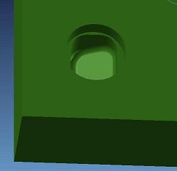
- Doesn't pay any attention to cut depths, it moves the tool straight to the selected surfaces even if they happen to be quite deep. For this reason, you must always run a Cavity Mill (or similar) operation first to remove the bulk of the material.
- Necessary for any mold that has any non-flat surface, such as in this picture:
Examples - Choosing an Operation
Choosing which operation to use depends on the type of mold you wish to machine. Here are a few examples:| Mold | Operations to Use |
|---|---|
| One or more cavities, where all the corners have radii that are not too tiny relative to the overall cavity dimension | Use a single Cavity Mill operation, with the largest end mill possible to achieve the desired radii. |
| One or more largish cavities with tiny radii on the corners. | Start with a Cavity Mill operation with as large a tool as possible to remove the bulk of the material. Follow with a Planar Mill operation using a tool small enough to achieve the corner radii. Use the Trim??????? option to limit the cutting area to just that corners that still need machining. |
One or more large cavities and one or more small cavities, as in this picture  |
Start with a Cavity Mill operation with a large tool to cut the large cavities. 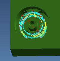 Then use a Planar Mill operation with a smaller tool to selectively machine the remaining small cavities. You may have to use a Trim????????? command to avoid cutting the large cavities again. 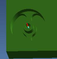 |
| Cavities with contours and non-flat bottoms |
Creating a Cavity_Mill Operation
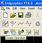
- Click on "Create Operation".
If the "Machining Environment" window pops up, select "CAM General" in the top window and "mill_contour" in the bottom window.
In the "Create Operation" window, select Type: "mill_contour", Subtype: "CAVITY_MILL" (top left button).
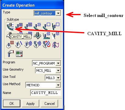
The CAVITY_MILL window will come up, which contains everything you need to define the toolpath:
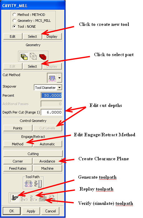
- Click the Tool button, hit Select, then New. For tool Name, enter whatever you want. Recommendation is to name it according to the chart above, for example for a 1/4" flat end mill, name it MILL_3. This makes it easy to keep track of things later, to remind you what tool you are using. Under the subsequent Milling Tool Parameters menu, enter the diameter in mm. You can put in stuff like 1/16*25.4 [to convert 1/16 to mm] and it will compute it for you. For ball end mills, you must also enter the ball radius into the (R1)Lower Radius box. No other parameters need to be filled out, but this is a good time to do a mental check of your tool length make sure your tool is long enough for your operations. Hit OK to close Tool window.
- Under Geometry, click on the left-most button named Part and then click on Select below it. Now click anywhere on your part to select it. Hit OK.
- Leave your Cut Method and 'Stepover' as default, but feel free to experiment with the effect of changing these.
- Set 'Depth Per Cut' according to the table of allowable cut depths above. For more control over cut depths, you can instead click the 'Cut Levels' button to enter another menu. Here you can directly specify the depth of each pass.
- To reduce the cutting time, you may want to modify the default Engage/Retract settings. Click on Engage/Retract -> 'Method' to enter the menu. Here, set the Initial Engage, Internal Engage, Final Retract, and Internal Retract all to 'Tool Axis'. This forces the tool to come straight down instead of a much slower spiral approach.
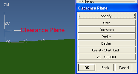
- Now you will create a clearance plane. By creating a clearance plane, you are telling Unigraphics to keep the cutting tool at some height above the wax block whenever it is moving from one place to another. Under Machining Parameters, choose 'Avoidance'. Click on 'Clearance Plane'. Click on 'Specify' and define your clearance plane to be offset 10 mm from the top surface by typing "10" in the box and clicking OK. Then, you should ALWAYS click on 'Display' in this sub-window to display the clearance plane--it will display a triangle which you should verify is the appropriate distance above the wax block. This is to prevent tool breakage.
- Now you can generate your tool path. There are two ways of doing this: Click on the bottom left-most button in the Planar_mill menu (FIG 8a), or right-click on Planar_mill in your operation navigator at the bottom of the screen to access the Generate command (FIG 8b):
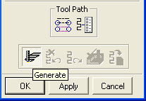 OR
OR 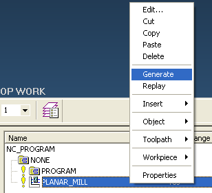
- To make changes, just double-click the operation you just made. You can change parameters and re-generate to see how it looks.
- Save your main .prt file in Unigraphics, so you dont have to do all this again if you want to redo it.
- To make multiple copies of the toolpath on your wax block, see the section below on Multiple Copies.
- To postprocess the toolpath into the form that can run on the Haas CNC, see the section below on Postprocessing
Creating a Contour_Area Operation
- 1 Click on "Create Operation".
If the "Machining Environment" window pops up, select "CAM General" in the top window and "mill_contour" in the bottom window.
In the "Create Operation" window, select Type: "mill_contour", Subtype: "CONTOUR_AREA".
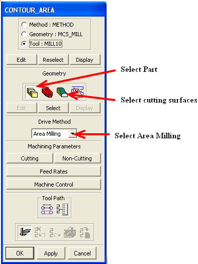
The CONTOUR_AREA window will come up, which contains everything you need to define the toolpath:
- Create a new tool as described in the Cavity Mill section above.
- Under Geometry, first click on the left-most button named Part and then click on Select below it. Now click anywhere on your part to select it. Hit OK.
- Still under 'Geometry', click on the third button named Cut Area, then Select. Now click on the surfaces you want to contour. Hit OK.
- Under 'Drive Method', select Area Milling. Even if is already selected, click and select it again. This will open a new window called 'Area Milling Method':
- Change the cutting Pattern to best match your part geometry. You may need to try several different Patterns to find the one that works best for your part.
- The Stepover box defines how Unigraphics calculates the distance between passes, which determines the smoothness of the surface. Choosing constant, you can then enter the distance between passes (when viewed from above). Choosing Scallop allows you to specify the maximum allowed scallop (step) height. This is nice, as it allows Unigraphics to adjust the stepover as needed throughout the surface to maintain the same suface finish. Setting the Stepover or Scallop to a smaller value leaves a smoother surface finish, but takes longer to machine.
- Hit OK to close the Area Milling Method menu.
- Now you generate your tool path as described earlier.
- To make multiple copies of the toolpath on your wax block, see the section below on Multiple Copies.
- To postprocess the toolpath into the form that can run on the Haas CNC, see the section below on Postprocessing
Creating a Planar Mill Operation
- Click on Create Operation. If the "Machining Environment" window pops up, select "CAM General" in the top window and "Mill Planar" in the bottom window.
In the "Create Operation" window, select Type: "mill_planar", Subtype: "PLANAR_MILL" (top, third from left).
The next window contains everything you need to define the toolpath:
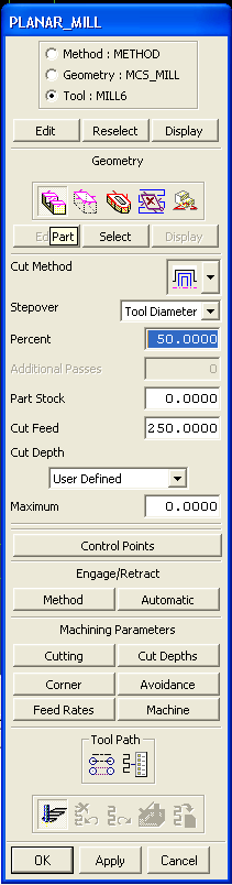
- Select the Tool button and edit it as MILL_3 which is a 1/4 (MILL_4 is a 1/8 and MILL_5 is a 1/16) depending on what size tool you are using. This is just a name to remind you what tool you are using. Under milling parameters, just check the tool length make sure your tool is long enough for your operations. (Make sure you enter diameter etc. in metric i.e. 1/8 = 3.175 mm). Note that you may have to make a New Tool: it will initially say Tool: None in the menu on top. Then you click Select, then New. In the subsequent menu you enter the diameter in metric. You can put in stuff like 1/16*25.4 [to convert 1/16 to mm] and it will compute it for you.
- Under Geometry, click on the left-most button named Part and then click on Select below it. (a) If you have a single depth, click on just the top surface of your part. (b) If you have multiple depths, choose the top surface and every lower surface including the bottom surface of your part and then exit.
- Again, under Geometry, click on the right-most button named Floor and then click on Select below it. Click on your bottom-most deepest surface of your part and then exit.
- Leave your Cut Method as default, but feel free to experiment with the effect of changing this.
- Leave Part Stock at 0.00 unless you want to leave a buffer around your part i.e. if you want to remove the wax around your SDM part after it is done so that you can chisel it out easier, choose 0.125 or so.
- Cut Feed sets the speed that the tool travels while cutting, in mm/min. The optimal speed varies greatly according to the tool diameter being used (see Tool Table). Recommendation is to leave this setting at 250 mm/min, and then modify the actual rate on the Haas.
- To reduce the cutting time, you may want to modify the default Engage/Retract settings. Click on Engage/Retract -> 'Method' to enter the menu. Here, set the Initial Engage, Internal Engage, Final Retract, and Internal Retract all to 'Tool Axis'. This forces the tool to come straight down instead of a much slower spiral approach.
- Under 'Machining Parameters', choose 'Cutting'. In the window that pops up, change the "Cut Order" to "Depth First" instead of "Level First". This will cut your part more efficiently.
- Under Machining Parameters, choose Cut Depths. A window will pop up allowing you specify minimum and maximum initial and final depths.
The maximum cut depth should be selected according to Tool Table. For fastest machining time, set the initial and final cut to the same as the maximum, but this can cause problems with shallow parts.
Hit OK to exit back to main menu. - Create clearance plane as described above.
- Generate toolpath as described above.
Making an Extraction Toolpath:
This tells you how to make an extraction toolpath that will cut the material from around your part, allowing you to easily pop it out of the mold. It is pretty similar to the Planar_Mill, but with a few differences. Do the following:- Click on Create Operation. If the "Machining Environment" window pops up, select "CAM General" in the top window and "Mill Planar" in the bottom window.
In the "Create Operation" window, select Type: "mill_planar", Subtype: "PLANAR_PROFILE" (second row, fourth from the left).
- When you select your part, don't select the entire wax block, just select the EDGE of the part that you want to cut around. That is, change the Mode to "Curves/Edges...". Leave the Curves/Edges settings as they are, i.e. Type=Closed, Plane=Automatic, Material Side=Inside. Then select a boundary (can be the boundary between the top of your part and the top of the wax block) that you want the extraction toolpath to cut around. If you have multiple parts you want to make extraction toolpaths around, then click "Create Next Boundary" after selecting an entire closed boundary. Then select another entire closed boundary, and so on. You can also even select different boundaries at different heights, and it should cut around them appropriately (check this though).
- Select the Floor as the deepest you want the extraction toolpath to go (this doesn't actually have to be the deepest thing in your part).
- You should probably put a Part Stock greater than 0 to leave a small buffer around your part. Miguel suggests 0.125.
- For "Cut Depth", pull down the menu and change it to "User Defined" rather than "Floor Only" which is the default. Then, in the "Maximum" box, put the maximum depth that mill bit is allowed to go per pass, from the Tool Table.
- For Engage/Retract, click on "Method", and make sure the "Initial Engage", "Internal Engage", "Final Retract", and "Internal Retract" are ALL set to "Tool Axis". Normally you just have to make the Initial Engage and Internal Engage "Tool Axis", but now you have to do the Retracts as well because otherwise it will go through the wax in weird places and possibly cut your other parts.
- Set the Clearance Plane in "Avoidance" as usual. Don't worry about the other menus. That's it!
Making multiple copies of the toolpath
- In order to generate multiple copies of your part on one block of wax, right-click on Planar_mill in the operation navigator window at the bottom of the screen and select Object -> Transform. Choose rectangular array. For the first box that shows up, enter where you want to map from your original part i.e. from the origin. For the second box that shows up afterwards (looks exactly the same as the first), choose where you want to start your array. Remember that XC and YC are relative to your current origin. Finally, choose DXC and DYC to separate your multiple transforms. You can accept or reject the parts as they are copied. Once accepted, the parts will show up on your drawing and your operational navigator.
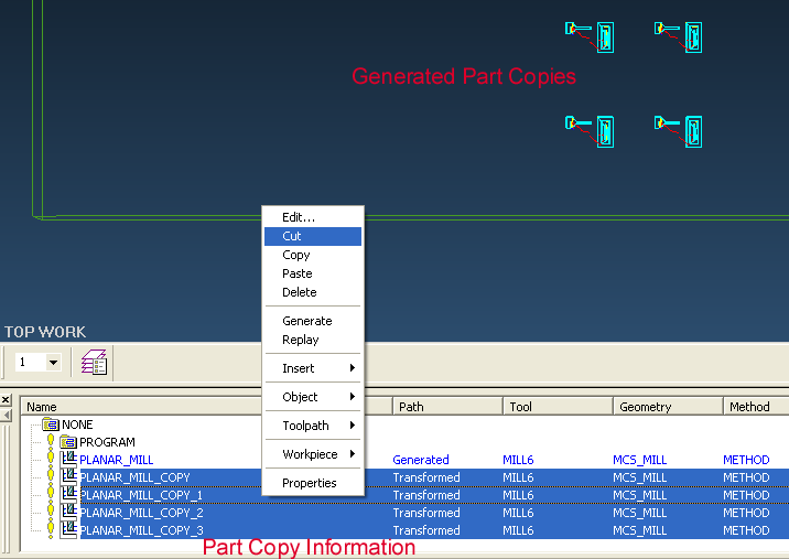
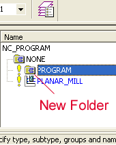
Now make a new folder, or "Program Group", by right clicking on the Program folder, then Insert -> Program Group .
Select all the parts and cut and paste them into the new Program Group using right-click menus.
Verifying your toolpath
- Red: Rapid Movements
- Yellow: Engage/Retract
- Blue: Cuts within the block
l You can watch a virtual tool run through your toolpath: rightclick on the icon representing your toolpath and select "Toolpath>Verify"
Postprocessing the toolpath
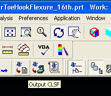
- Now you will begin the process of exporting your toolpath into a format the Haas mill can understand. Select the new project folder holding all your parts to highlight it, and then select Output CLSF from the button bar.
- In the Output CLSF window, turn off list output and leave your file the same name as the UG file part name you have. Also leave it as CLSF standard. Check off the box next to program. Hit OK.
- Now, go to the Tools menu -> CLSF. Select the CLSF file you just made. Click on Select All from CLSF manager, click on Postprocess.
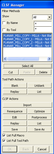
In the NC Postprocessing window that pops up, under MDF Name, choose Specify and select the "haas2.mdfa" file (attached here, haas2.mdfa). Click on Postprocess in that window. - UG will now churn the code for you a black Graphics Postprocessor Module will show up. If you have small arcs in your design, you may generate errors which you can ignore. (Note: For all other errors in this step, see the note about Unigraphics file names at the top of this page). Click Yes to continue and save all files generated.
- Open up the folder with your postprocessed files in it. You should have several new files with the suffixes .ptp, .cls, and .lpt. You can delete the .cls and .lpt files. Open the .ptp file up in a text editor (Notepad). Delete the first two lines of the file after the %. Open up the Header and Footer text file (attached here, headerandfooter.txt). Copy and paste the header into the location where you just deleted the two lines. Copy and paste the footer at the very end of the file. Finally, change two values to the correspond to the correct tool that you are using i.e. if you are using 1/8 tool i.e. MILL_4, make sure that on line 5 of the header you have T4 and on line 9 of the header you have H4.
- Save this file somewhere you can access it over the web.
Combining ptp Files
CombiningPtpFiles - Cutting and Pasting ptp files -- if you want it to machine things faster.Machining on the HAAS in the RPL
All of this information has been moved to MachiningOnTheHAAS since this page was getting quite long. -- AlanAsbeck - 23 May 2006Casting Urethane
Uncured urethane has hazardous fumes. Be sure to read the MSDS for the correct urethane before pouring. Do as much of the process as possible in the fume hood (making sure to cover the surface with paper towels).- Use tape (duct or clear packing tape) to create a dam around the section of the wax block where you intend to pour.
- Put wax block in vacuum chamber and draw vacuum to 30 inHg. Leave for about a minute, then release vacuum. Leave block in vacuum chamber.
- Gather the following things:
- Plastic beaker
- Tongue depressor for stirring
- 2 large Ziploc bags for waste
- Put beaker on scale and tare.
- Take bottles of resin and hardener out. Note that the ratio of ratio/hardener is written on the bottles.
- Pour the desired amount of resin or hardener (it's generally easier to do the more viscous one first). Then zero the scale and pour the other part to meet the specified ratio. This can be poured by hand, or for more accuracy, a dropper can be used for the last few grams.
- Mix vigorously for 30 seconds with a stirrer such as a tongue depressor.
- Take the beaker with urethane and pour the urethane into your mold, pouring at least 3-4mm above the top surface of your parts.
- Close the lid of the vacuum chamber and turn on the vacuum pump. Leave it on for 1-3 minutes. The vacuum should stay around 30 inHg. The urethane will start to bubble and expand in volume. It will continue bubbling vigorously as the trapped air bubbles expand and rise to the surface. After a few minutes the bubbling will gradually subside and the urethane will get very clear of bubbles. Now turn off the pump and open the exhaust valve.
- Let the part cure for at least 12 hours (varies with the type of urethane) before trying to machine or extract it.
Table of Info for Polymers
Here is a list of info on polymers that we have (or had) to work with. Please update the paper copy in the RPL if you make significant changes here (or just print out another).| Polymer Name | Working Time | Cure Time | Mix by Volume | Mix by Weight | Shore Hardness | Tensile Strength | Young's Modulus | Elongation | Cured Color | Manufacturer | Polymer Type | Notes |
|---|---|---|---|---|---|---|---|---|---|---|---|---|
| Dragon Skin | 20 min | 5 hours | 1A:1B | 1A:1B | 10A | 475 psi | ? | 1000% | Translucent-White | SmoothOn | Silicone | tap silicone thinner used successfully |
| EcoFlex 0010 | 30 min | 4 hours | 1A:1B | 1A:1B | 10A | 200 psi | ? | 800% | Tanslucent-Clear | SmoothOn | Silicone | |
| Vytaflex 10 | 30 min | 16 hours | 1A:1B | ? | 10A | 160 psi | ? | 1000% | Clear-Amber | SmoothOn | Urethane | |
| Vytaflex 20 | 30 min | 16 hours | 1A:1B | ? | 20A | 200 psi | 195 kPa | 1000% | Off-White | SmoothOn | Urethane | |
| Silastic S | 45 min | 7 hours | 10A:1B | ? | 26A | 1000 psi | 900% | Green | DowCorning | Silicone | ||
| Vytaflex 40 | 30 min | 16 hours | 1A:1B | ? | 40A | 522 psi | ? | 660% | Off-White | SmoothOn | Urethane | |
| SmoothCast 60D | 5 min | 20 min | 1A:1B | ? | 60D | 2200 psi | ? | 30% | Amber | SmoothOn | Urethane | |
| SmoothCast 61D | 7 min | 60 min | 1A:1B | ? | 61D | 1800 psi | ? | 20% | Amber | SmoothOn | Urethane | |
| SmoothCast 305 | 7 min | 30 min | 1A:1B | 10A:9B | 70D | 3000 psi | ? | ? | White | SmoothOn | Urethane | |
| SmoothCast 326 | 8 min | 60 min | 1A:1B | ? | 72D | 3170 psi | 61600 psi | ? | Clear Amber | SmoothOn | Urethane | |
| SmoothCast 327 | 15 min | 4 hours | 1A:1B | ? | 72D | 3170 psi | 61600 psi | ? | Clear Amber | SmoothOn | Urethane | |
| Task 3 | 20 min | 90 min | 1A:1B | 120A:100B | 80D | 6650 psi | ? | 6% | White | SmoothOn | Urethane | |
| Task 9 | 7 min | ~4 hrs | 1A:1B | 115A:100B | 85D | 7800 psi | ? | 6% | Clear | SmoothOn | Urethane | |
| IE-10AH | 10 min | 10 hours | ? | ? | 10A | 150 psi | ? | ? | White | Innovative Polymers | Urethane | |
| IE-20AH | 12 min | 10 hours | ? | 100R:100H | 20A | 200 psi (datasheet) 190 psi(measured) |
217 kPa | 175% | White | Innovative Polymers | Urethane | |
| IE-50AC | 12 min | 4 hours | 51R:100H | 50R:100H | 55A | 1000 psi | ? | 470% | Clear | Innovative Polymers | Urethane | |
| IE-60A | 10 min | 8 hours | 22R:100H | 25R:100H | 55A | 1000 psi (datasheet) 200psi (measured) |
560 kPa | 470% | Cream | Innovative Polymers | Urethane | |
| IE-72DC | 15 min | 4-6 hours | 100R:55H | 100R:50H | 80D | 8000 psi | ? | 2% | Clear | Innovative Polymers | Urethane | |
| P-20 | 60 min | 18 hours | ? | 10A:100B | 20A | 525 psi | ? | 425% | Translucent | Silicon Inc/Innovative Polymers | Silicone | |
| P-44 | 60 min | 24 hours | 10.9A:100B | 10A:100B | 42A | 600 psi | ? | 250% | Translucent | Silicon Inc/Innovative Polymers | Silicone | |
| P-70 | 60 min | 24 hours | 13.9A:100B | 10A:100B | 58A (70A after a week+) | 775 psi | ? | 150% | Light Green | Silicon Inc/Innovative Polymers | Silicone | |
| P-100 | 60 min | 24 hours | 13.2A:100B | 10A:100B | 80A +/- 10A | 470 psi | ? | 345% | Tan/Beige | Silicon Inc/Innovative Polymers | Silicone | |
| TAP Blue | 30 min | 8 hours | 9A:1B | 10A:1B | 26A | 580 psi | ? | ? | Light Blue | TAP Plastics | Silicone | |
| FXRite 12 | 60 min | 16 hours | 10:1 | 10:1 | 12A | ? | ? | ? | Translucent | ArtMolds | Silicone | |
| EPM-2492 | 2 hours | 6 hours | ? | 1A:10B | 75A | 200 psi | 1643 psi | 250% | White | NuSil | Silicone | |
| Sylgard 170 | 15 min | 24 hours @ 25 deg C 20 min @ 70 deg C |
1A:1B | 1A:1B | 40A | ? | ? | ? | Dark Grey to Black | Dow Corning | Silicone | |
| GI 1040 | 1.5-2.5 hrs | 16 - 18 hrs | 100:11.3 | 10:1 | 30A (40A after 7 days) | 525 +/- 25 psi | 225 +/- 25 psi | light blue | Silicones Inc. | Silicone (tin cured) |
What Cures and Bonds to What
Here is a table quickly explaining which polymers cure on each other and which ones bond to each other* Polymer_properties_spreadsheet.xls: Color coded table for what Polymers stick and cure to each other *Note that this setup implies the curing of a polymer ON TOP of a base. The tests performed did not examine how well a polymer will cure given small features. For instance, Sylgard 170 will cure on IE20, but any features will not come out.
| Base | ||||||||||||
|---|---|---|---|---|---|---|---|---|---|---|---|---|
| P-20 (clear white) | P-44 (clear pink) | P-70 (green) | P-100 (beige) | Sylgard 170 (black) | TAP Blue | Vytaflex 10 | Vytaflex 20 | Vytaflex 40 | IE 20 (white) | GI 1040 (light blue) | ||
| P-20 (clear white) | full cure mild bond |
full cure no bond |
full cure no bond |
full cure mild blond |
full cure no bond |
no cure no bond |
no cure no bond |
no cure no bond |
no cure no bond |
full cure no bond |
||
| P-44 (clear pink) | full cure full bond |
full cure full bond |
full cure full bond |
full cure full bond |
full cure mild bond |
no cure no bond |
top cure no bond |
top cure no bond |
top cure no bond |
full cure no bond |
||
| P-70 (green) | full cure full bond |
full cure full bond |
full cure full bond |
full cure bond |
full cure full bond |
no cure no bond |
no cure no bond |
top cure no bond |
top cure no bond |
full cure mild bond |
no cure no bond |
|
| P-100 (beige) | full cure full bond |
full cure full bond |
full cure mild bond |
full cure bond |
full cure mild bond |
no cure no bond |
top cure no bond |
top cure no bond |
top cure no bond |
full cure no bond |
||
| Sylgard 170 (black) | full cure bond |
full cure full bond |
full cure full bond |
full cure full bond |
full cure full bond |
no cure no bond |
no cure no bond |
no cure no bond |
no cure no bond |
full cure no bond |
||
| TAP Blue | full cure bond |
full cure mild bond |
full cure full bond |
full cure full bond |
full cure mild bond |
full cure full bond |
full cure no bond |
full cure no bond |
full cure no bond |
full cure no bond |
||
| Vytaflex 10 | full cure no bond |
full cure no bond |
full cure no bond |
full cure no bond |
full cure no bond |
full cure no bond |
full cure full bond |
full cure bond |
full cure bond |
full cure no bond |
||
| Vytaflex 20 | full cure no bond |
full cure no bond |
full cure no bond |
full cure no bond |
full cure no bond |
full cure no bond |
full cure full bond |
full cure bond |
full cure bond |
full cure no bond |
||
| Vytaflex 40 | full cure no bond |
full cure no bond |
full cure no bond |
full cure no bond |
full cure no bond |
full cure no bond |
full cure full bond |
full cure mild bond |
full cure bond |
full cure no bond |
||
| IE 20 (white) | full cure no bond |
full cure no bond |
full cure no bond |
full cure no bond |
full cure no bond |
full cure no bond |
full cure mild bond |
full cure mild bond |
full cure mild bond |
full cure full bond |
||
| GI 1040 (light blue) | full cure no bond |
|||||||||||
- headerandfooter.txt: Header and footer for PTP files
Ideas, requests, problems regarding TWiki? Send feedback