new web: http://bdml.stanford.edu/pmwiki
TWiki > Haptics Web>StanfordHaptics>BendingSurgicalTool (05 Nov 2009, SanthiElayaperumal)
MRI-compatible Haptics: Deflection and Force Sensing of Biopsy Needles and other tools using FBG sensors
Cryoprobes
A potential application for the MRI-compatible strain sensors include integration on probes for cryosurgery. The following notes were taken while observing a procedure for BPH (Benign Prostatic Hyperplasia) treatment. BPHCryosurgeryNovemberDesign References
Extensions to the sensorized MRI-compatible needle include: imaging integration to change the MR scanning plane; a haptic manipulator for prostate biopsy; and actuation for a steerable needle. The following notes were collected this summer. DesignReferencesSummer2009Active Tooling
LiteratureReviewForActiveTooling -- to be filled out by scryuSensorized Tooling
ISMRM 2009
- Y-L. Park, S. Elayaperumal, S.C. Ryu, B. Daniel, R. J. Black, B. Moslehi, and M.R. Cutkosky, "MRI-compatible Haptics: Strain sensing for real-time estimation of three dimensional needle deflection in MRI environments", International Society for Magnetic Resonance in Medicine (ISMRM) 2009, 17th Scientific Meeting and Exhibition, Honolulu, Hawaii April 2009
- ISMRM2009_MRICompatibleHaptics_final.ppt: Slides from Oral Presentation given at ISMRM 2009.
ISMRM 2008
- Y-L. Park, S. Elayaperumal, B.L. Daniel, E. Kaye, K.B. Pauly, R.J. Black, and M.R. Cutkosky, "MRI-compatible Haptics: Feasibility of using optical fiber Bragg grating strain-sensors to detect deflection of needles in an MRI environment", International Society for Magnetic Resonance in Medicine (ISMRM) 2008, 16th Scientific Meeting and Exhibition, Toronto, Canada, May 2008
Background
The manipulation of catheters, needles and other minimally invasive devices to reach tumors and other targets is the initial step of nearly all MRI-guided interventions. To date, most research on MRI targeting has focused on using MR to image the target, and to plan the trajectory of interventional devices. During the +pparatus into the interventional devices, which further increases device complexity including adding the need for appropriate patient isolation electronics. New project(s) on estimating the curvature and/or loading on sensorized, elastic tooling used in surgical applications.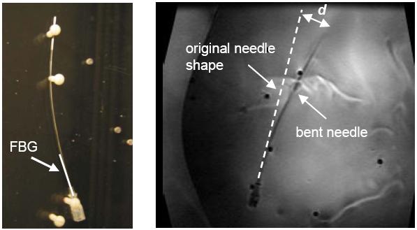
Biopsy Needle
note: May 6th is the conference in Toronto. Assume a long, slender biospy needle that has strain gages (e.g. fiber optic bragg cell gages) bonded to it. The needle deflects as it is inserted. We would like to estimate the actual profile taken by the needle and/or the forces imposed on it. MRC: What I'd like to do is start by illustrating the basic issues and looking at some test cases. I'd rather do a physically-based solution than an artibrary one. Also we need to start compiling a list of references (e.g. Bicchi, various beam/sensor location papers, etc. for a literature review. We'll need this anyway). NeedleCalibrationAndBendingAnalysis -- new page started for MihyeShin 24 Nov 2008 %ENDCOMMENT% Starting points:- assume long, slender beam; beam theory applies
- sensors measure the curvature at discrete points along the beam
- assume needle either passes through a couple of fixed locations (e.g. over bones) or else has some forces imposed on it. Boundary conditions apply:
- zero deflection and slope at base, without loss of generality
- possibly zero moment and hence zero curvature at tip
- main force may be at the tip (this force might dominate the loading)
Forward force and displacement problem
Force: Given a set of N loads at known locations along the beam, the deflection of the beam can be computed using the moment/curvature equation. Displacement: Given that the beam passes through a set of fixed points (e.g. over one peg and under another) the curvature and profile of the beam is again uniquely determined. This is a version of the classic elastic spline problem. It is usually solved by energy minimization.- Glass 1966: - elastic spline as energy minimization BV problem. This paper provides a simple formulation of the energy minimization problem for an elastic spline that goes through N fixed points. The result is a nonlinear 4th order differential equation. The solution method is probably more complicated than what we want to do (suboptimal discretization would be fine).
- http://people.csail.mit.edu/bkph/papers/Least_Energy.pdf
- A Criterion for the Optimal Design of Multiaxis Force Sensors
- An approach to optimise the critical sensor locations in one-dimensional novel distributive tactile surface to maximise performance
- Multi-component force sensor based on multiplexed fibre Bragg grating strain sensors
MRI-Compatible Robotics Article Summaries
July 16, 2008 The articles summarized include review studies about MR-compatible materials, actuators, sensors, and other limitations. Also, state-of-the art technologies and manipulators are presented. The current favorite actuation method is ultrasonic motors. However MR-compatible, they still produce significant image artifact when ON.- MagneticResonanceArticles_July16.doc: articles include review studies, fluidic actuation comparison, and a new USM for use inside the MR scanner
- PaperSummary.doc: articles describe MR-compatible manipulators (PZT, pneumatic), and a 3-DOF joystick
Sensor Placement
(Some cleanup of this section preformed Nov 2009. Look to past revisions or attachment table to access other linked files.) So far, two models were used to determine the best locations for two sensors along the length of the needle. The first model describes a force-based approach, in which the actual curvature and deflection is calculated from two known forces applied at known locations. The next model uses a known deflection profile of a bent needle. The mathematics that describe both methods are found in "Sensor Placement Estimation.ppt". Next: Modeling using parametric curves and minimum energy splines. Parametric representation allows for more degrees of freedom to describe a curve in space. In this approach, the (x,y,z) position of any point along the length of the needle is described as a function of u. x,y, and z are not given as functions of each other. The example attached shows how by knowing the curvature at given sensor positions, a multiple-part profile of the needle curvature can be determined.- ParametricFormofCurves.ppt: Description of interpolating a deflection profile given curvature information at specific locations along the needle.
- Bendingin2Planes.ppt: Math to solve parametric coefficients assuming small deflections and no torsion.
- SmallDeflectionsModel.ppt: Results for simplified math simulations.
- PointandDistributedLoading.ppt: Results for distributed loading models which give the same curvature as two point loading at x = 0 and x = L/2.
Bio-compatible Adhesives
Loctite provides several cyanoacrylate instant adhesives for medical device use. They don't need uv-light for curing. They have been qualified to Loctite's ISO 10993 Protocol. Following is the catalog link of the Loctite's products. http://www.ellsworth.com/display/productlisting.html?ProductLineID=12&VendorID=155&SubcategoryID=34&Tab=vendors Part #: 18680, 18686, 20268, 20269, 37732, and 37733 can be used for medical device.Interviews
On the future of robotic surgery: RickSatava (11/8/08)Papers
ISMRM Abstract and full paper drafts are in the private section of the Twiki. IsmrmAbstract?Ideas, requests, problems regarding TWiki? Send feedback