new web: http://bdml.stanford.edu/pmwiki
TWiki > RisePrivate Web>TWikiUsers > SalomonTrujillo > DCMotorThermalExperiments>ImmersionCurrentDriver (22 Jul 2008, SalomonTrujillo)
Instructions
This amplifier converts an analog voltage signal to a current. The input signal is referenced against ground. The dual amplifier configuration allows the amplifier to operate across the full supply voltage.Schematic
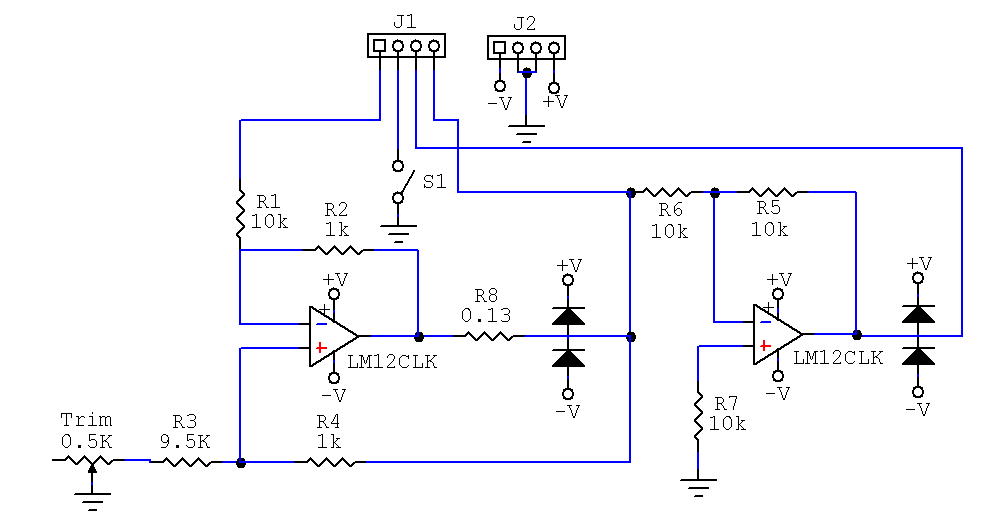
Ripple suppression
The output displays a 100 mV pk-pk sine wave at 60 kHz. In order to remove this oscillation, a 0.1 uF capacitor is placed across resistor R2.Trim Pot Tuning
Consider the combined resistance of resistor R3 and the trim pot as . The trim pot must be adjusted such that:
Current Gain
The gain equation is which gives approx. 1 amp/volt ratio for this amplifier.
Derivation
R8 is the current sensing resistor. Designate the output of the first op-amp as and the amplifier output at
  such that the voltage drop across R8 is
Also, designate the input signal as
 . Thus, for the op-amp inputs, we find that

Using op-amp analysis, we assume
 and get
We can re-arrange this as

At this point choose
 such that
(This is how we adjust the trim pot, this equation can be simplified to the trim pot equation)
Which simplifies the above equation to

Using ohm's law across resistor R8

Which can be re-arranged to find the gain equation. -- SalomonTrujillo - 28 May 2008
Ideas, requests, problems regarding TWiki? Send feedback