new web: http://bdml.stanford.edu/pmwiki
TWiki > RisePrivate Web>TWikiUsers > SalomonTrujillo>DCMotorThermalExperiments (12 Aug 2008, SalomonTrujillo)
To Do
-
Verify calibration of thermometer. -
Calibrate IR sensor using resistance method with templistik. - Calibrate IR thermistor using the oven in the RPL.
-
Order surface thermistors. - Consider new wooden IR sensor mount for motor-coil only view.
- Calibrate resistance method in RPL oven.
- Calibrate surface thermistors.
- Verify IR calibration.
- Run experiments on motor rig
-
Write MATLAB script to simulate various models - Figure out if lumped capacitive model will work for motor coil.
- Find parameters to fit model to data
- Create sensors for RiSE robot
- Program sensors for the RiSE robot
- Develop RiSE code to climb using new control method
- Execute control method
- Get TeXshop? working
- Figure out ICRA LaTeX? template.
- Write the paper
Data
- Currently, the updown logs and the IRCalib log are the only valid data. The rest are corrupted because the sensor wasn't mounted properly.
Thermal Model
- At this point, we will attempt to model the magnetic core, the motor windings and the motor case, as three lumped thermal capacitors. We assume there is a thermal resistance between core-windings, winding-case and case-air, but we don't worry about modeling the case-air resistance, because we have a measurement of the case temperature at all times.
- The motor current will cause an injection of heat into the motor windings. We assume the IR sensor can give us winding temperature and the digital sensor can give us case temperature (albeit, it might be low-passed.) We need to find out if the sensor is good enough to give us an accurate reading.
Setup
Mechanical
Mounting
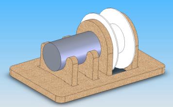
- MotorMount.zip: Compressed ZIP of Solidworks Files
Properties
- Spool diameter: 29.0 mm
Digital Thermometer
- The digital thermometer probably has a better thermal conduction path along it's leads, so I've bend the leads to nearly make contact with my target surface, and gap the distance with thermal paste. The connect must be solid, because if the leads touch the motor casing, it will short 5v and ground. I'm considering placing a thin square of electrical tape on the casing to protect against shorts. According to a #M page, electrical tape is supposed to have good thermal dissipation (need to check on the brand we have.)
Electrical
IR Thermometer
- Calibration:
- Internal Thermocouple gain: -0.37946 Celisus/A2D ticks
- IR Equilibrium output: 59.5 A2D? ticks (According to the in oven calibration)
- IR gain = 1.9248 Celisus/A2D ticks
- Thermocouple offset must be recalibrated each day
Motor
- Terminal Resistance: 0.67 ohm
Drive Electronics
- Current Gain: 0.96 mA/D2A_tick (4096 D2A? _ticks = ~5 volts)
- ImmersionCurrentDriver: The Impulse Engine voltage-to-current amplifier.
Software
- Current software is located in the svn repository svn://yoda.stanford.edu/svn/users/sal/PIC in the AutomaticMotorControl and SimpleMotorControl directories
Version A
This first version of the automatic control repeatedly raises and lowers a 350 gram mass, using different forces. The states of the controller are as follows:- Prewind: A quick jolt will remove all slack from the line and raise the mass slightly off the floor. The duration is fixed
- Rest: This state holds the mass at using a gravity-compenstated force, and allows the system to come to rest slightly above the floor. The duration is fixed.
- Wind: The motor draws the mass upward, quickly. This is the primary source of heat. The masses displacement is fixed, thus the duration is variable.
- Brake: The motor release the motor, allowing gravity to brake the mass. This state ends when the mass reaches a desired downward velocity.
- Unwind: The motor provides a near gravity compensating force, gently lowering the mass to the ground. This is the secondary source of heat. It's duration is fixed.
- Release: The motor returns to the brake motor force. It will remain here such that the combined duration of the brake and release states are fixed.
- Wait: This state waiting until the combined duration off all seven states is equal.
Ideas, requests, problems regarding TWiki? Send feedback