new web: http://bdml.stanford.edu/pmwiki
TWiki > Rise Web>ClimbingRobot>TrajectoryAnalysis (07 Jun 2004, MiguelPiedrahita? )
-- JonathanKarpick - 01 Jun 2004
MatlabTrajectoryAnalysis - a rundown of the current state of the Matlab Trajectory effort. -- MiguelPiedrahita? - 16 Apr 2004
The tasks described below have been implemented, and are described in this Powerpoint presentation: Trajectory_04-16-04_Stanford_ver5.ppt -- MiguelPiedrahita? - 06 Apr 2004
The task at hand:
We would like to provide a way for a user to specify a leg trajectory in an intuitive fashion; possibly by graphically specifying beta_dot versus beta (i.e. the velocity along the trajectory as a function of the trajectory position), and phi versus beta (wing angle as a function of trajectory position).
This trajectory description then needs to be mapped through the inverse kinematics to the information needed by the RiSE (or test track) motor controllers. For RiSE, we need the positions of the two motors driving the differential. For the test track, we need the positions of the motor controlling the 4-bar and the motor controlling the wing angle.
The trajectory input and mapping algorithm will initially consist of 3 Matlab modules. All modules will use the linkage geometry specified in the file "riseconfig.mat". Here is the high-level pseudocode for what's going on in each module:
Module 1: Allow the user to graphically specify beta_dot versus beta and phi versus beta. Not sure how to do this yet!
Convert this data into the column matrices "beta" and "phi", each 360 entries long (for 360 time steps). Save to risedata.mat
Module 2: Using 4-bar kinematics equations and geometry from "riseconfig.mat", create a table mapping from psi to beta. Read matrix "beta" from "risedata.mat". Interpolate using the table to create a new column matrix "psi" (crank angle), which then has 360 entries corresponding to the value of psi at each time step. Save to risedata.mat
Module 3: Load matrices "psi" and "phi" from "risedata.mat". Load gear radii for the differential from "riseconfig.mat". Use kinematic equations for the differential to create new column matrices "theta1" and "theta2", each with 360 entries, which represent the motor positions on the RiSE hip corresponding to the specified "psi" and "phi" values for that time step. -- MarkCutkosky 7 April 04
Here are some sketches and ideas by MotohideHatanaka based on preliminary testing of claws on the climbing wall. The tests were done moving the linkage by hand (the linkage is back-drivable). The conclusion is that specification of the equilibrium orientation and the compliance of the toe and claws with respect to the lower leg is (of course) a multi-objective optimization problem in which detachment is perhaps as important as attachment! -- MiguelPiedrahita? - 02 Apr 2004
Initial drawings of definitions used for trajectory analysis.
Define a reference frame fixed to robot body at the point where ground link and crank link meet: xo,yo,zo where xo is pointing right and yo is pointing forward.
<href="http://bdml.stanford.edu/twiki/pub/Rise/TrajectoryAnalysis/3DTrajectory_2-2.bmp">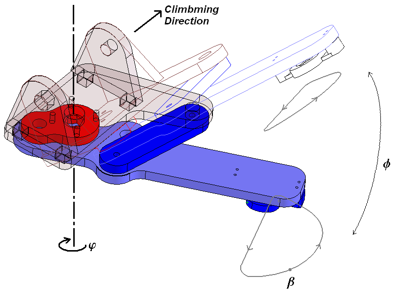
More images and whiteboard captures below...
MatlabTrajectoryAnalysis - a rundown of the current state of the Matlab Trajectory effort. -- MiguelPiedrahita? - 16 Apr 2004
The tasks described below have been implemented, and are described in this Powerpoint presentation: Trajectory_04-16-04_Stanford_ver5.ppt -- MiguelPiedrahita? - 06 Apr 2004
The task at hand:
We would like to provide a way for a user to specify a leg trajectory in an intuitive fashion; possibly by graphically specifying beta_dot versus beta (i.e. the velocity along the trajectory as a function of the trajectory position), and phi versus beta (wing angle as a function of trajectory position).
This trajectory description then needs to be mapped through the inverse kinematics to the information needed by the RiSE (or test track) motor controllers. For RiSE, we need the positions of the two motors driving the differential. For the test track, we need the positions of the motor controlling the 4-bar and the motor controlling the wing angle.
- phi - wing angle, as measured about yo, from xo to plane of four-bar.
- beta - location on the 4-bar (planar) trajectory, where beta is defined to be equally spaced along the trajectory.
- psi - crank angle, measured positive as shown in picture.
- theta1 - angular position of motor 1 (front motor)
- theta2 - angular position of motor 2 (rear motor). Theta1 and theta2 are defined to be 0 when phi=psi=0.
The trajectory input and mapping algorithm will initially consist of 3 Matlab modules. All modules will use the linkage geometry specified in the file "riseconfig.mat". Here is the high-level pseudocode for what's going on in each module:
Module 1: Allow the user to graphically specify beta_dot versus beta and phi versus beta. Not sure how to do this yet!
Convert this data into the column matrices "beta" and "phi", each 360 entries long (for 360 time steps). Save to risedata.mat
Module 2: Using 4-bar kinematics equations and geometry from "riseconfig.mat", create a table mapping from psi to beta. Read matrix "beta" from "risedata.mat". Interpolate using the table to create a new column matrix "psi" (crank angle), which then has 360 entries corresponding to the value of psi at each time step. Save to risedata.mat
Module 3: Load matrices "psi" and "phi" from "risedata.mat". Load gear radii for the differential from "riseconfig.mat". Use kinematic equations for the differential to create new column matrices "theta1" and "theta2", each with 360 entries, which represent the motor positions on the RiSE hip corresponding to the specified "psi" and "phi" values for that time step. -- MarkCutkosky 7 April 04
Here are some sketches and ideas by MotohideHatanaka based on preliminary testing of claws on the climbing wall. The tests were done moving the linkage by hand (the linkage is back-drivable). The conclusion is that specification of the equilibrium orientation and the compliance of the toe and claws with respect to the lower leg is (of course) a multi-objective optimization problem in which detachment is perhaps as important as attachment! -- MiguelPiedrahita? - 02 Apr 2004
Initial drawings of definitions used for trajectory analysis.
Define a reference frame fixed to robot body at the point where ground link and crank link meet: xo,yo,zo where xo is pointing right and yo is pointing forward.
<href="http://bdml.stanford.edu/twiki/pub/Rise/TrajectoryAnalysis/3DTrajectory_2-2.bmp">
More images and whiteboard captures below...
Ideas, requests, problems regarding TWiki? Send feedback