new web: http://bdml.stanford.edu/pmwiki
TWiki > Rise Web>FootDesign>RiSEAnkleDescription (27 Apr 2006, AlanAsbeck)
The good ankles are those seen in the pictures on RiSESpinyFeetNov -- if the plastic part where it attaches to the lower leg looks different than in those photos, it is the old version. We have also made some changes to the bottom of the ankles to adjust for the compliant sticky pads. These changes are documented below. We (Stanford) do not have any good ankles left, so we cannot measure the stiffness properties quantitatively, however we can give a qualitative analysis.
There are a few other features that we currently do not have in the ankles, but would be beneficial to climbing: 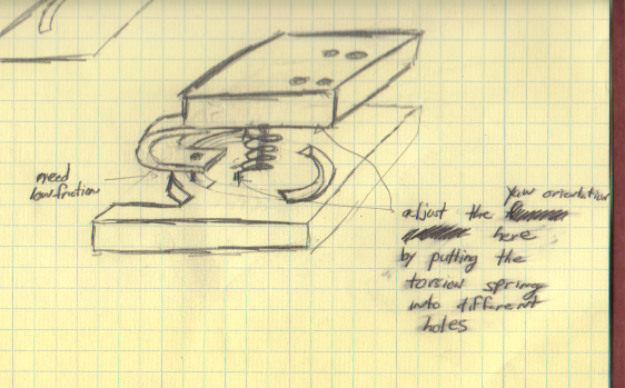
Table of desired ankle compliances:
| Direction | Description |
|---|---|
| Yaw compliance | Should be weak enough to permit the foot to rotate ~50 degrees during the stance phase without causing the foot's operation to be negatively affected. If it is too stiff, the toes can be sheared sideways excessively when the ankle has rotated a lot. However, it must be stiff enough to return the foot to an upright position after it has rotated the ~50 degrees it does during the stroke. If you make it too weak, the foot will list to one side or another instead of being upright. Also, having damping in this direction is ideal (but not necessary) because the foot is a relatively large mass which moves a fair distance, and it can oscillate when it returns to the upright position. The best bet is probably to make it just barely stiff enough to return the foot to an upright position and have it not list to the side. We use sorbothane as a damping material, however, we may want to come up with an alternative solution. I think we want to stay away from glueing any sort of flexible material to the ankles. This is where human error come into play in the manufacturing process and we get failures. |
| Roll compliance | The roll compliance must be relatively soft, almost as soft as possible. A minimum bound on the softness is that the foot shouldn't flop around and should return to some nominal orientation when no load is applied. The foot needs to readily conform to the surface with minimal applied normal force (just the pressure of the robot resting against the wall). We have found no evidence to date that damping is needed in this direction. |
| Pitch compliance | The pitch compliance is the stiffest of the three compliances. The ankle must be stiff enough to have the back of the foot not touch the wall or only very very lightly touch the wall. If the back of the foot presses heavily against the wall, the toes will disengage much more readily. But, this compliance must not be too stiff either, for two reasons. (1), some mechanical compliance is useful in having the robot conform to the wall as well as possible, particularly on irregular surfaces, and (2), the toes must be oriented properly with respect to the wall, and this is achieved by having the back of the foot be pretty close to the wall. The foot must resist pitchback, which if occured, would prevent any spines from engaging. Damping is probably useful in this direction as well but the present ankles seem to work fine without damping. |
- 2 or 4 screw holes to properly attach to the lower leg. We currently use a single screw hole.
- If we do go to 2 or 4 screw holes, then we need to be aware of the fact that we need to either adjust the yaw angle, or properly align the foot so that it is pointing straight up at the begining of the stride. An adjustable yaw angle might be cumbersome, but it would be very beneficial for making last minute adjustments.
- An adjustable roll angle MAY be needed, but probably not. At
SwRI, we needed to place small shims on the inside of the ankle/lower leg interface to slightly adjust the roll angle, probably because the roll compliance was too stiff as a result of our ankle repairs. If the roll angle is incorrect, the feet only engage on one side or the other. It is probably the case that with the correct roll compliance, no roll adjustments would be necessary, but this should be verified to make sure. - Dimensions are given here: AnkleDimensions.BMP: Numbers given with a ~ sign can be modified. Dimensions without the ~ sign can only be changed with changes to other parts. Please try to keep these dimensions as is.
- A
SolidWorks model of the current ankle is given here: BallJointSolidModel.zip Some of the dimensions may be slightly different from the diagram above because of manufacturing inaccuracies.
Design Ideas
Matt Idea 1:
This uses a torsion spring located around the ball joint stud to provide the proper yaw stiffness without adding too much roll or pitch stiffness. The C-springs are added in the pitch direction to give the proper pitch stiffness. Yaw angle orientation is adjusted by placing the ends of the torsion spring in different holes that exist on the top and bottom plates of the ankle.
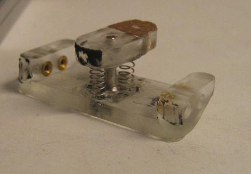
Alan Idea 1:
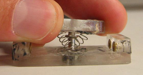
This is essentially the same as the current ankles except you weld compression springs to the top and bottom plates in the place of the polyurethane flexures. In the prototype below I just superglued them, but using something much more permanent would be necessary. By using compression springs with an appropriately wide spacing between turns of the spring, you prevent the compressed spring in the front of the ankle from getting squished too much. In this rough prototype the springs seem to hold up well to extreme displacements. These springs were a little softer than should be used in a real ankle, however (I just picked some out of a container we had).- Iso View:
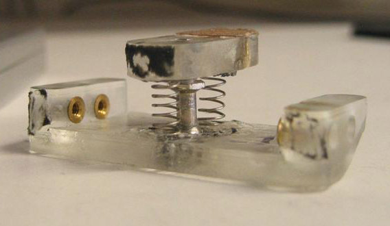
- Iso View 2:
- Pitched forward to limit of ball joint (20-30 deg?):
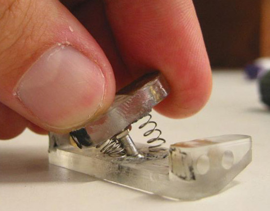
- Rolled to limit (30 deg?):
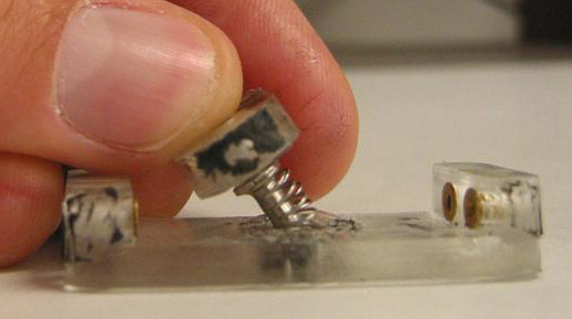
- Yawed 60+ degrees (I forget exactly how much, you can yaw it over 100 degrees):
- Design parameters for controlling the pitch, yaw, roll compliances with this design: Spring length, spring constant, radial distance of springs from ball joint, diameter of spring, can also have multiple springs in groups rather than just one in front and one in back.
Alan/Matt other ideas:
- Similar to Matt Idea 1, you could have a big C-spring in the front of the ankle. But instead of having a slot on the bottom piece, just have it slide over the top of the bottom piece.
- Have two top pieces (the egg-shaped thing in the pictures that the ball joint is screwed into), and have the top one be able to rotate relative to the bottom one and then be locked down so you can adjust the yaw-offset of the ankle.
- There's no reason why the top plate has to extend towards the back of the ankle--you can put screw holes right on either side of the ball joint thread.
- Matt thought to put the ball joint into the bottom piece, you could have a hole in the bottom that you push the ball joint and thread up through, then glue or attach a second thin plate on the very bottom to secure the ball joint in its little socket.
- There is also the option to make asymmetric right and left ankles.
- Put in hard stops to prevent excessive rotation and spring/flexure over-extension?
Ideas, requests, problems regarding TWiki? Send feedback