new web: http://bdml.stanford.edu/pmwiki
TWiki > Rise Web>MicrochipTutorial (11 Aug 2009, SalomonTrujillo)
Tutorial on how to use the Microchip PICs with the hockey puck programmer.
..As taught by the one and only SalomonTrujillo, black belt in the PIC programming arts.- If it's not installed download MPLAB from Microchip (the compiler requires a registration from you.)
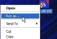
- Open MPLab as Administrator
- Right-click on the MPLAB icon to access the "Run As" command. Use the username Administrator and cooresponding password (ask!)
- Right-click on the MPLAB icon to access the "Run As" command. Use the username Administrator and cooresponding password (ask!)
- Get datasheet from microchip.com
- Low pin count
- great for minor projects, doing stuff fast
In MPLab: (Adding print screens for all of this stuff would be helpful)
Project -> Project Wizard Next --> select PIC18F1320? Next --> Active Toolsuite: Microchip C18 Toolsuite- You shouldn't have to touch the Toolsuite Contents and Location boxes.
- If the toolsuite isn't present, the student edition can be downloaded from microchip.com
- Preferable to put it in C:\Users\_____
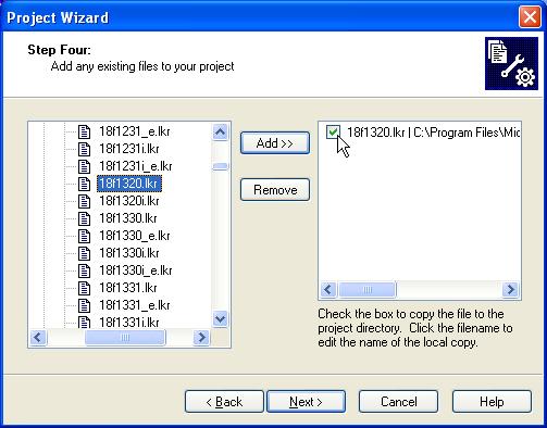
- Program Files\Microchip\MCC18\lkr\your pic.lkr
- If there are several different filenames corresponding to your PIC, choose the one with the shortest name.
- Click on the Add button to bring this file into your project.
- Check the box to make a local copy of the file instead of using the master copy.
Making your file:
- File --> New
- Save As... main.c (not required but recommended by Sal)
//#include <p18cxxx.h>
#include <p18f1320.h>
// p18fxxx.h doesn't exist.. this one works even though we're using an F chip
// Add whichever one works for your chip.  If they don't have one for your chip, use an xxx one.
// Search in:
//    Program Files\Microchip\MCC18\h\
// for a file to correspond to your chip.


void main(void)
{

// End all files with infinite loop:
// not defined what happens if main() returns.

  for(;;);

}
Next: - Right click on Source Files on left side
- Click on "Add Files" and open "main.c"
- Build it by right clicking on "main.c" and clicking on "Compile"
Must configure the PIC:
Configure --> Configuration Bits... Uncheck the box which says "Configuration Bits set in code" and set the following:- Oscillator: INT RC-Port on RA6, Port on RA7
- Most likely you don't want an oscillator. The other ones all use an external crystal, this one uses the microchip internal RC thing. Is limited to 8MHz with internal, with crystal can get up to 40 MHz.
- Power Up Timer: Enabled
- Watchdog Timer: Disabled
- Important!! --> normally turned on, is used to make sure the processor doesn't hang--it will reset if this isn't poked periodically. So we disable it to not have to deal with all of this.
- Master Clear Enable: enabled (MCLR enabled, RA5 input disabled)
- Is whether you want to use a particular pin as a reset line (RA5). (Sal likes having a reset line)
Now hook up the programmer:
- go to the datasheet--Pin Diagrams
- we have 18 pin PDIP
- On the little red board with the programmer, make the appropriate connections according to the pin diagram.
- VSS is ground.
- Need to connect every connection except for redundant power pins.
- Vpp is the only pin that can handle 12 volts. Vpp = programming voltage
- because we set the MCLR (Master Clear) pin also, 0V = reset, 5V = run, 12V = program chip
- Pins can source 25mA!
- However, total for all pins together has some limitation also.
- Should really put a bypass cap -- 0.1uF -- between power and ground as close to the microprocessor as possible. Really helps prevent resets.
Now: make internal oscillator fast--starts at a really slow speed
Look for the OSCCON register in the data sheet (as of this edit, page 19). This register, among other things, controls the speed of the internal clock. Upon startup, the processor runs at 31 kHz (way too slow.) Using OSCCON, we can increase the speed to 8MHz. All of the registers in the datasheet have a cooresponding variable declared inp18f1320.h
Look for OSCCON register *WHERE?!?! In the data sheet?* -- this is the speed of the internal clock - --> With the pic we're using today: set bits 4,5,6 to high (in code) This can be accomplished by writing:
OSCCON |= 0x70;
      1 = 0000 0001
 1 << 3 = 0000 1000
~(1<<3) = 1111 0111

^= means XOR

Usage: we want to Toggle bit 3 on PortB
LATB ^= (1 << 3);

And this, the LATB ends up as the same thing as you started with, except the bit you want (bit 3) is now low.
Takes several clock ticks per loop in the for-loop.. hard to calculate LED flashing frequency
Build your code! *What exactly do we build, and where? Do we want to Toggle Port B? Where should that code be added?*
Programming the chip:
Programmer -> Select Programmer -> MPLAB ICD 2- (this is the programmer we use in the BDML)
- Power tab: make sure "Power target circuit from MPLAB ICD 2" is checked.
- Only do this if you're using the little breakout board (ZIF)
- Otherwise if you're doing in-circuit programming like stickybot you don't need to
Using the A/D Converter:
Assorted notes: Set voltage reference--the bounds of the A/D range Only one A/D for the whole chip--need to select which input pin it is using at a time. Takes time switching between input pins because it needs to settle... Set things in binary: 0b.......- -->not in standard C, just the microchip environment
Using the timers:
The internal PIC clock runs at whatever speed we set it to (via OSCCON register)--this frequency is denoted Fosc. The timers will tick one tick per instruction cycle. In the P18F1320? one instruction is executed every 4 clock ticks, so if our oscillator is at 8MHz (Fosc = 8MHz) then instructions will be executed at 2MHz. So, the timers will increment at 2MHz. To use the timers (in this case Timer0), do something like:oldTime = TMR0; while((unsigned char)(TMR0) - oldTime) < 50);If the timer is set up as 8-bit, the number you count up to can only go up to 256. If it is set up as 16-bit, you can count up to 65,536. The subtraction will always work out correctly (even if the timer wraps around, which it will) if you cast the subtraction as an unsigned char (for 8-bit) or unsigned int (for 16-bit). Setting up the timers: The datasheet is pretty self-explanatory. The prescaler slows down the timer by some factor. Cool!
Circuit picture, schematic, and code for the LED blinker:
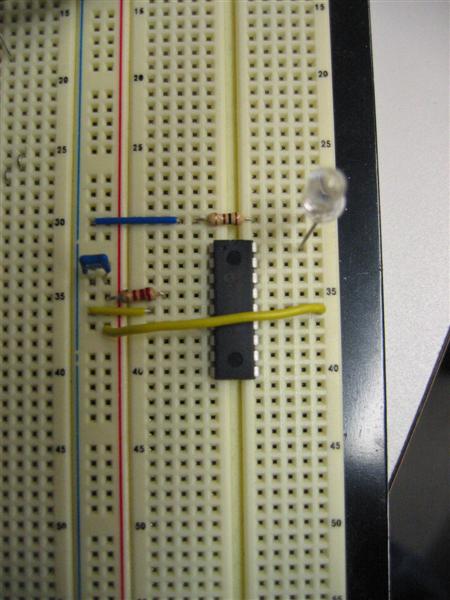
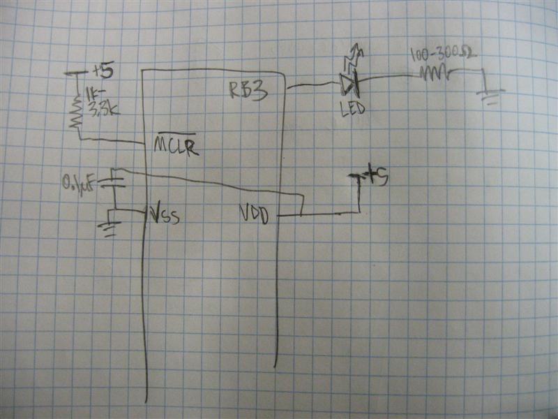
This circuit just flashes an LED.- led_blink.c: LED Blinker code
- LED Blinker circuit:
- LED Blinker schematic:
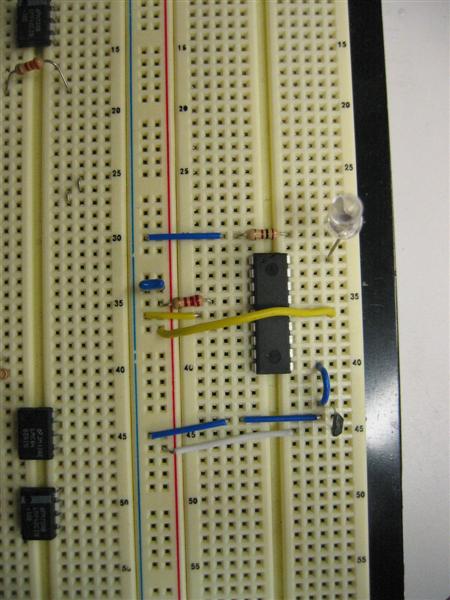
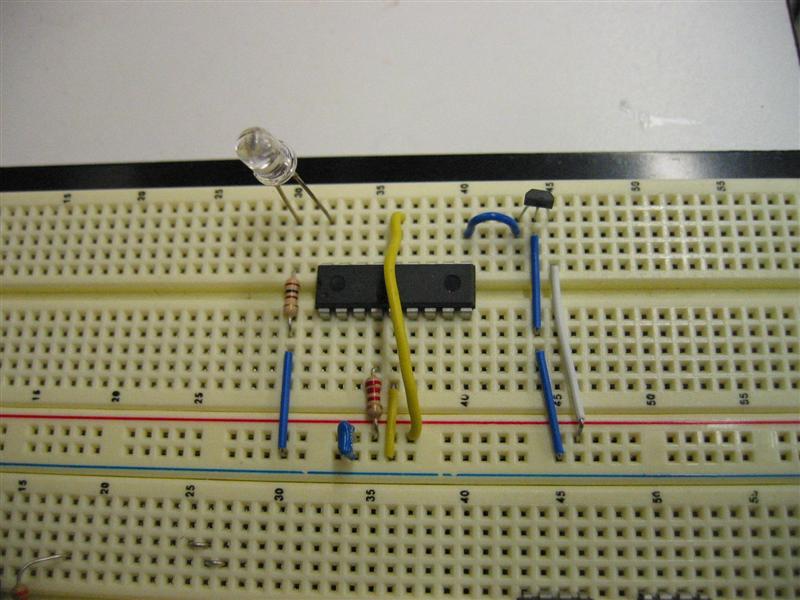
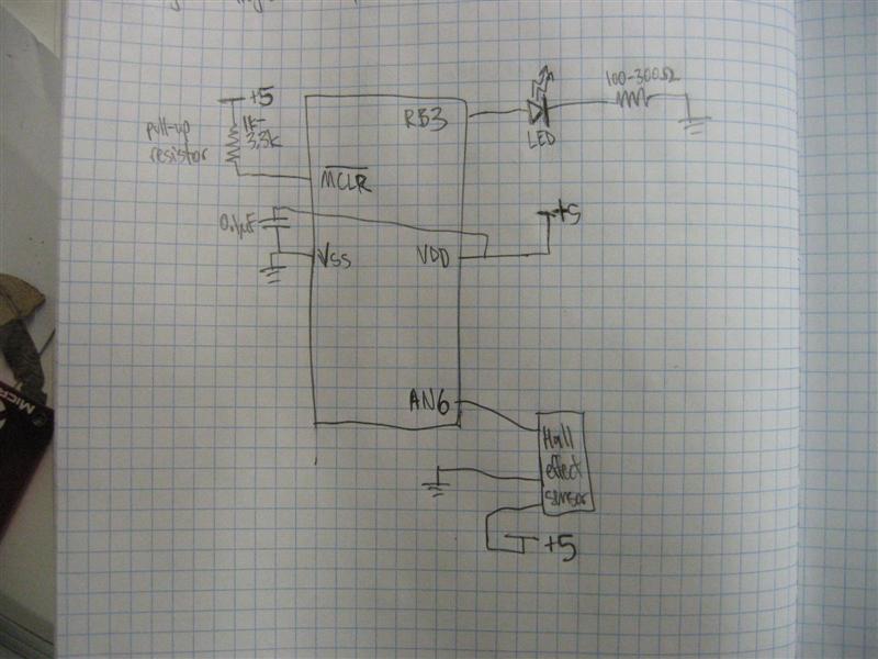
Circuit picture, schematic, and code for Hall effect blinker:
This circuit turns on the LED when a magnet is held close to the Hall effect sensor, with either end (North or South) towards the hall effect sensor. The PIC reads in the analog voltage from the Hall effect sensor using the A/D converter.- hall_effect_led.c: LED Hall effect code
- LED Hall effect circuit 1:
- LED Hall effect circuit 2:
- LELED Hall effect schematic:
Ideas, requests, problems regarding TWiki? Send feedback