new web: http://bdml.stanford.edu/pmwiki
TWiki > Rise Web>ClimbingRobot > LegSensingAndActuation>AnalogAccelerometerPCB (06 Jan 2005, WillP? )
Alan and I have designed a small PCB for the accelerometers intended to used on RiSE in the legs/feet of the robot. They provide mounting for the accelerometer (an Analog Devices ADXL210AE? or ADXL202AE? ) and solder pads for required resistors and capacitors (0603 package) as well as through-holes for ribbon or discrete wire connections. The resistor is required for setting the chip oscilator frequency and capacitors are required for local supply decoupling and setting signal bandwidth (which is coupled to the signal noise-floor).
The boards were assembled by soldering the accelerometer by reflow soldering with low temp solder paste (200 degree C melt, Sn43Pb43Bi14? , Kester 286LT) on a hot plate (set to 225 deg C). Chip resistors and capacitors were soldered with the same solder paste and a soldering iron. Cable connections were made with standard wire solder on the tails of the stripped cable ends (poked through the PCB).
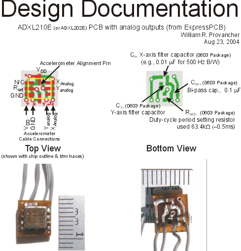
- PCB layout and chip locations:
Ideas, requests, problems regarding TWiki? Send feedback