new web: http://bdml.stanford.edu/pmwiki
TWiki > Haptics Web>StanfordHaptics > PhotonicRobots>Prototype2 (09 Apr 2008, YongLaePark)
Prototype 2
The first prototype has already confirmed the feasibility of the 3-D exoskeletal robot finger structure with an embedded FBG sensor as shown in the first quarterly report. It has shown reasonable linearity and sensitivity as a force sensor. However, the calibration tests showed relatively large hysteresis. The thermal expansion and creep of polymer-based structures have been suspected as major reasons. The design of the second prototype has focused on reducing these two problems. In addition, different material has been considered for the new prototype to reduce bubbles captured during the casting process in the structure.1. Design Modification and Improvement
Two major features have been added in the new prototype: a copper mesh (080X080C0055W36T, TWP Inc.) and a temperature compensation sensor for thermal effects and creep prevention. Copper mesh has been embedded into the outside of the skin structure, and a temperature compensation sensor is embedded into the inner structure as shown in Figure 1.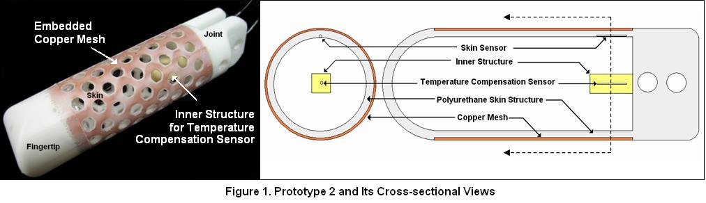 It is unavoidable to experience higher creep effect in a polymer structure than in a metal structure. The creep prevents the force sensing skin structure from having complete linearity and repeatability which are mainly dependent on the stiffness and resilience of the structure. The embedded copper mesh into the polymer structure is expected to reduce this creep problem. In addition, the copper mesh has another important function: heat shield [1]. The high conductivity of copper expedites distribution of heat applied from outside of the skin and creates a more uniform heat region inside the skin structure.
Since embedded FBG sensors are sensitive to temperature change as well as strain change, it is necessary to provide a function to isolate thermal effects from strains. The inner structure is designed to be free from strains caused by external force applied to the skin structure. Only one end of the inner structure is attached to the joint part of the finger, and this will result in little deformation of the inner structure even as the outside skin structure experiences deformation.
It is unavoidable to experience higher creep effect in a polymer structure than in a metal structure. The creep prevents the force sensing skin structure from having complete linearity and repeatability which are mainly dependent on the stiffness and resilience of the structure. The embedded copper mesh into the polymer structure is expected to reduce this creep problem. In addition, the copper mesh has another important function: heat shield [1]. The high conductivity of copper expedites distribution of heat applied from outside of the skin and creates a more uniform heat region inside the skin structure.
Since embedded FBG sensors are sensitive to temperature change as well as strain change, it is necessary to provide a function to isolate thermal effects from strains. The inner structure is designed to be free from strains caused by external force applied to the skin structure. Only one end of the inner structure is attached to the joint part of the finger, and this will result in little deformation of the inner structure even as the outside skin structure experiences deformation.
2. Material Selection
Different materials have been considered for the second prototype. The material used in the first prototype (IE-72DC) has reasonable stiffness and hardness. However, the mixed viscosity is too high to remove most of air captured when resin and hardener are mixed. The material used in the second prototype (Task 3) has similar properties in hardness and stiffness but much lower mixed viscosity, so it enabled the structure to have fewer air bubbles during the casting process. Task 8 has been used for the inner structure for embedding the temperature compensation sensor due to its resistance to heat. Figure 2 shows how the new material improved the degassing process. The first prototype made of IE-72DC (Figure 2.a) polyurethane has a big air bubble in the bonded area, but the second prototype made of Task 3 (Figure 2.b) has only small bubbles. See Material Selection for properties of possible materials.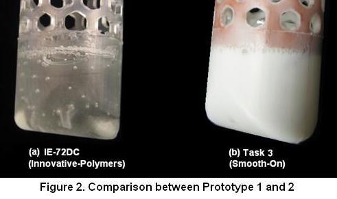
3. Fabrication Process
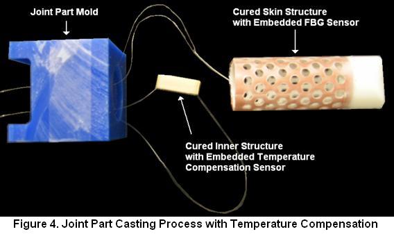
A copper mesh is embedded during the skin structure casting process. The copper mesh is inserted between the inside mold and outside mold as shown in Figure 3, and then liquid polyurethane is poured through the gap. The temperature compensation sensor is installed during the joint part casting process. Already cured skin and inner structures are put into the liquid polyurethane. Figure 4 shows the skin and inner structures to be put into the joint part mold.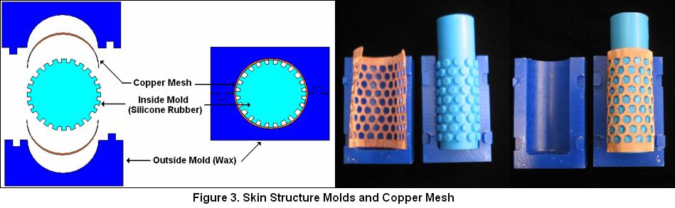
4. Force Sensing Test and Analysis
Three different types of tests have been carried out to check the performance of the new prototype: point force application on the skin structure, grasp force application on the finger tip, and dynamic thermal effect test. 4.1. Skin Contact Force Application on the Skin Structure Point forces are slowly loaded up to 11~12 N and unloaded back to zero at a specific spot on both front and back sides of the skin using a scale and a height gage. Figure 4(a) shows where the force is applied and the skin sensor is located, and Figure 4(b) the test setup. Three identical tests have been conducted on the front side and two tests on the back side. The results are shown in Figure 4(c). The positive forces are applied to the front side and the negative ones to the back side. The results show higher linearity and repeatability in both front side and back side force applications in the new prototype than in the previous prototype, which does not have an embedded copper mesh. However, the slope of the output signal for front side forces is much steeper than that of back side forces. This means the sensor is more sensitive to the front side force applications (as expected since the sensor is only embedded into the front side skin). The wavelength shifts of the temperature compensation sensor are also measured. Even though forces are applied and the output of skin sensor continuously changes, the temperature compensation sensor hardly changes its output regardless of applied forces. This confirms that the inner structure for embedding temperature compensation sensor is almost strain free.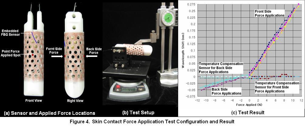 4.2. Grasp Force Application on the Fingertip
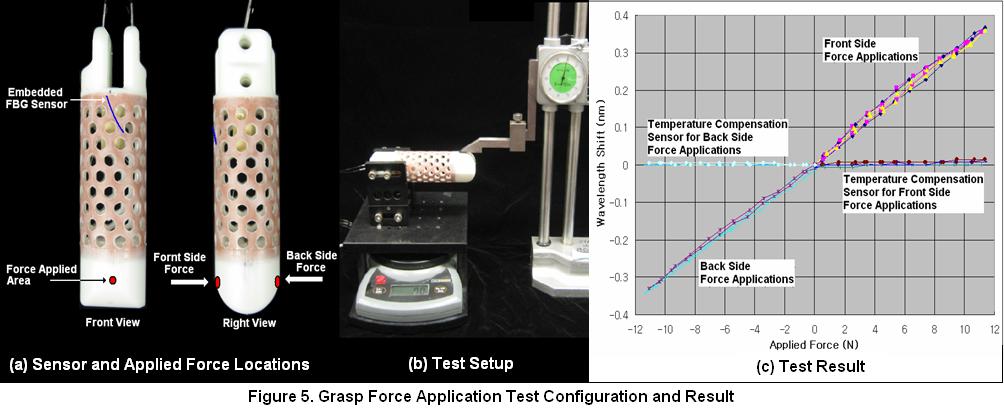
Since the finger should detect and measure the grasp forces applied to the fingertip as well as collision forces applied to the skin structure, grasp force tests have been carried out to calibrate the structure as a force sensor. Perpendicular forces to the finger axis are slowly loaded up to 12 N and unloaded back to zero to the finger tip in the same way of point force application test in 1.4.1. Figure 5(a) shows where and how the forces are applied, and Figure 5(b) the configuration of the test setup. Three identical tests have been conducted on the front side and two tests on the back side.
Positive and negative forces refer front side and back side forces respectively.. The result is shown in Figure 5(c). The output signal (wavelength shifts) for different force applications are highly linear and repeatable. In comparison to the previous point force application test, the slopes of output signals for both front side and back side forces are almost the same. This means the embedded force sensor can be used as a load cell to measure grasp force applied on the fingertip, and it confirms that the structure may be able to distinguish the grasp forces from collision forces applied to the skin.
The temperature compensation sensor shows almost no wavelength shift in this test too. Therefore, it confirms that it is installed at a strain-free spot.
4.2. Grasp Force Application on the Fingertip
Since the finger should detect and measure the grasp forces applied to the fingertip as well as collision forces applied to the skin structure, grasp force tests have been carried out to calibrate the structure as a force sensor. Perpendicular forces to the finger axis are slowly loaded up to 12 N and unloaded back to zero to the finger tip in the same way of point force application test in 1.4.1. Figure 5(a) shows where and how the forces are applied, and Figure 5(b) the configuration of the test setup. Three identical tests have been conducted on the front side and two tests on the back side.
Positive and negative forces refer front side and back side forces respectively.. The result is shown in Figure 5(c). The output signal (wavelength shifts) for different force applications are highly linear and repeatable. In comparison to the previous point force application test, the slopes of output signals for both front side and back side forces are almost the same. This means the embedded force sensor can be used as a load cell to measure grasp force applied on the fingertip, and it confirms that the structure may be able to distinguish the grasp forces from collision forces applied to the skin.
The temperature compensation sensor shows almost no wavelength shift in this test too. Therefore, it confirms that it is installed at a strain-free spot.
 4.3. Dynamic Thermal Effect Test
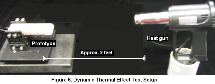
Although it is already checked that the temperature compensation sensor is strain-free in this prototype, it is not clear how well the sensor behaves to eliminate the thermal effects on the skin. To check the dynamic thermal response of two sensors, the finger structure was heated up to 40 degrees (Celsius) using a heat gun as shown in Figure 6, and the heat source was removed. Then, the temperature and the output signals (wavelengths) were measured every 20 seconds. The room temperature was 23.7 degrees.
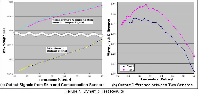
Two tests were carried out, and the result is shown in Figure 7(a). As temperature decreases, the wavelengths from both sensors decrease together. This means both sensors behave similarly as temperature changes. However, a closer look at the system shows that the wavelength differences of the two sensors are not always constant. The difference changes are small at high temperature but large at low temperature as shown in Figure 7(b). The reason is that the skin sensor is even closer to the copper mesh than the temperature compensation sensor, and this makes the skin sensor more sensitive to heat. As a result, the skin sensor shifts its wavelength more at high temperature than the temperature compensation sensor, for which the inner structure made of polymer insulates the heat applied.
The second prototype has proven the feasibility of temperature compensation by installing a strain-free dummy sensor. However, the current design is not fast enough to provide accurate compensation under rapidly varying thermal conditions.
4.3. Dynamic Thermal Effect Test
Although it is already checked that the temperature compensation sensor is strain-free in this prototype, it is not clear how well the sensor behaves to eliminate the thermal effects on the skin. To check the dynamic thermal response of two sensors, the finger structure was heated up to 40 degrees (Celsius) using a heat gun as shown in Figure 6, and the heat source was removed. Then, the temperature and the output signals (wavelengths) were measured every 20 seconds. The room temperature was 23.7 degrees.
Two tests were carried out, and the result is shown in Figure 7(a). As temperature decreases, the wavelengths from both sensors decrease together. This means both sensors behave similarly as temperature changes. However, a closer look at the system shows that the wavelength differences of the two sensors are not always constant. The difference changes are small at high temperature but large at low temperature as shown in Figure 7(b). The reason is that the skin sensor is even closer to the copper mesh than the temperature compensation sensor, and this makes the skin sensor more sensitive to heat. As a result, the skin sensor shifts its wavelength more at high temperature than the temperature compensation sensor, for which the inner structure made of polymer insulates the heat applied.
The second prototype has proven the feasibility of temperature compensation by installing a strain-free dummy sensor. However, the current design is not fast enough to provide accurate compensation under rapidly varying thermal conditions.
5. Plans for Next Quarters
Since the second prototype confirmed the feasibility of the copper mesh and a temperature compensation sensor for thermal effect and creep prevention, multiple sensors will be embedded into the skin structure to localize the force applied to the skin as well as to measure more accurately the grasp force. For the temperature compensation sensor to be more useful, development of a better fixture design and installation method are required. The compensation sensor should be more responsive to heat, and the wavelength shift should be more consistent with that of the skin sensors. When the fabrication with multiple sensors is completed, the finger will be integrated to the Stanford Dexter robot arm for development of adaptive filtering and feedback control algorithms.Reference
[1] A. Dollar, C.R. Wagner, and R.D. Howe, Embedded Sensors for Biomimetic Robotics via Shape Deposition Manufacturing, Proceedings of the first IEEE/RAS-EMBS International Conference on Biomedical Robotics and Biomechatronics, 2006 -- YongLaePark - 02 Jun 2006Ideas, requests, problems regarding TWiki? Send feedback