new web: http://bdml.stanford.edu/pmwiki
TWiki > RisePrivate Web>StickyBotForceController? > GaitFileFormat>StanceController (11 Sep 2006, SalomonTrujillo)
Stance Controller
The Stance Controller determines position deltas for all servos assuming that all the legs are in stance. If not all the legs are in stance, it is the responsibility of the high-level controller to select which deltas to use.Stroke Motor Control
The inputs to the system are the forces read from the sensors, f, a feed-forward, grasp-space velocity, vFF, and a (constant) desired grasp_space force, fD. The output is a set of deltas for all servo positions. The block diagram for the controller is shown below.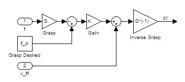 All control is done in grasp space which allows the controller to deal with the important interactions between the legs (i.e. total force exerted by the legs). The grasp matrix G converts forces to grasp-space forces, and its inverse G-1 converts from grasp-space velocities to command velocities (servo command deltas). The diagonal proportional gain matrix K relates the grasp space forces to grasp space velocities.
The most recent force data, f for the stroke motors is fed through the grasp matrix G to determine the forces in grasp-space. This is then subtracted from the desired grasp-space forces, fD and the difference is multiplied by the grasp-space gain K . Then the feed forward term vFF is added and the result translated to command deltas through the inverse grasp matrix, G-1 .
All control is done in grasp space which allows the controller to deal with the important interactions between the legs (i.e. total force exerted by the legs). The grasp matrix G converts forces to grasp-space forces, and its inverse G-1 converts from grasp-space velocities to command velocities (servo command deltas). The diagonal proportional gain matrix K relates the grasp space forces to grasp space velocities.
The most recent force data, f for the stroke motors is fed through the grasp matrix G to determine the forces in grasp-space. This is then subtracted from the desired grasp-space forces, fD and the difference is multiplied by the grasp-space gain K . Then the feed forward term vFF is added and the result translated to command deltas through the inverse grasp matrix, G-1 .
G Matrix Example
Here are some examples of grasp space forces that could be incorporated into a G matrix as well as the row that would be included in the G matrix. First, the leg order (0-3) is front left, front right, rear left, rear right.- Total Force -

- Torque (left - right) -

- Front Leg Force -

Wing Motor Control
Eventually we should have sensors measuring wing force, and we will want to control the wing angle to keep a reasonable normal force on each foot. For now we will simply try to keep the wing at the nominal position. This means that attachment does not need to make sure the wing comes back to nominal after the preloading stage. For now the inputs to the system are the vector of nominal wing positions (relative to home), Wnom, and the wing velocity value, vwing. If the current position of the wing is not the appropriate value (in Wnom) then the wing is moved towards nominal at a maximum speed given by vwing.Foot Motor Control
The foot motors are controlled in the same manner (and for the same reasons) as the wing motors. The inputs for the foot motor system are the down position (relative to home), Fdown, and the maximum foot speed, vfoot. -- BarrettHeyneman - 08 Aug 2006Ideas, requests, problems regarding TWiki? Send feedback