new web: http://bdml.stanford.edu/pmwiki
TWiki > RisePrivate Web>StaticModeling? > FrictionAdhesionOptimization>PlanarVerticalExample (18 Apr 2006, DanielSantos? )
-- DanielSantos? - 14 Apr 2006
Figures for Frictional Adhesion Paper.
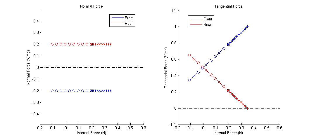
Example 1 - Planar Model with 2 Contact Points on Vertical (90 degree) Flat Surface.
- Mass = 50 grams
- COM Height = 2cm
- Stride Length = 10cm
- Mu = 1
- Alpha = 30 degrees
- Fmax = m*g
- GP_Vert1.jpg:
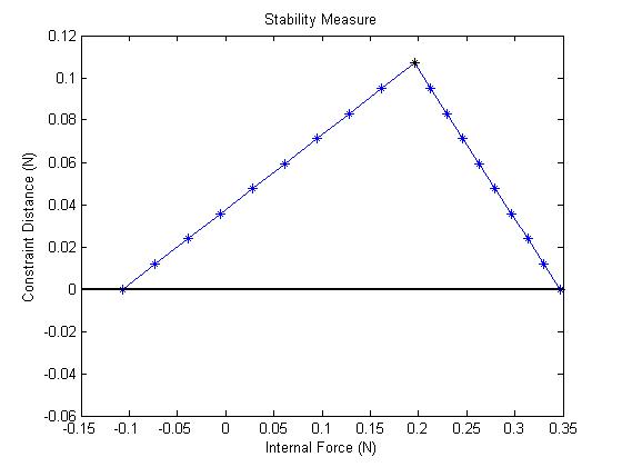
- GP_Vert2.jpg:
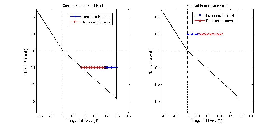
- GP_Vert3.jpg:
Ideas, requests, problems regarding TWiki? Send feedback