--
DanielSantos? - 25 Mar 2006
Static Modeling with Frictional Adhesion
We explore the static stability of a 3D 4-legged robot or animal on an inclined flat plane.
There are 6 static equilibrium equations - Sum of Forces in X, Y, Z are 0, and Sum of Moments about X, Y, Z are 0.
Assume that each foot is in point contact (no moments) with surface.
There are 12 unknowns - 4 feet in contact with surfaces, at each contact 3 Forces (x,y,z).
At each contact, the contact forces must also satisfy the contact constraints.
Contact constraints include things like Coulomb friction, etc.
So, there are now more unknowns than equations.
Physically, these extra unknowns correspond to "Internal Body Forces" - i.e. the force a robot/animal can exert squeezing on a tree trunk.
These "Internal Body Forces" are essentially degrees of freedom that the controller can use.
In this analysis we use these dof to maximize our stability.
We define stability to be the minimum distance from violating any one of the contact constraints at each foot/surface contact.
We can then explore how stability and forces are related and how they change as a function of model parameters.
2D Model
Model Description
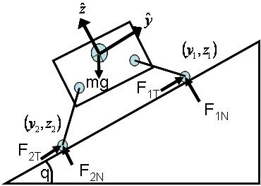
We first start with a simple 2-Dimensional Model that has 2 legs in contact with an inclined plane.
In this case, there are only 3 static equilibrium requirements and 4 unknowns.
This leaves one degree of freedom, which is the "pinch" force between the two feet in this case.
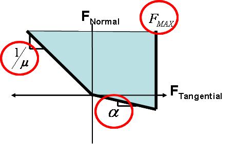
The two pictures below show a graphical representation of the model and the contact constraints at each foot contact.
The following parameters were then assumed:
- Mass = 10 grams
- y1 = -y2 = 5cm
- h = 2cm
- mu = 1
- alpha = 1/sqrt(3) (30 degrees)
- Fmax = m*g
Contact Forces
We then look at two cases:
- Front and Rear foot in the same orientation (both feet generate frictional adhesion in same direction)
- Rear foot oriented 180 degrees wrt Front foot (feet generate frictional adhesion in opposite directions)
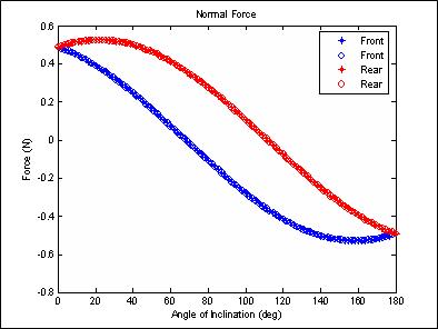
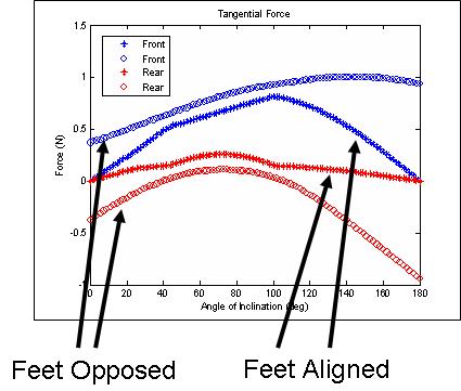
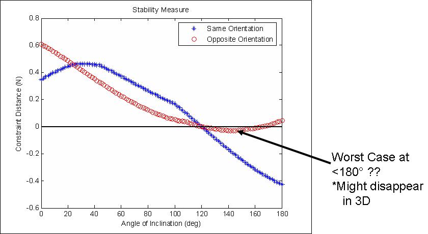
These two plots show the contact forces at the front and rear feet for both cases as a function of surface incline.
In the reversed case, we see that the analysis has the two feet pulling inward towards each other, even on level ground.
This is because that will result in "greater" stability, even though, in reality, on level ground there is no real need for greater stability.
However, this might be what one might want to do if an external force was pulling the animal/robot off of the surface.
In the inverted case, the feet in the reversed orientation pull in towards each other to an even greater degree.
Stability
This plot shows the maximum stability that can be achieved in either case as a function of surface incline.
Values below zero result in failure.
Notice that the worst case scenario is actually less than fully inverted.
At fully inverted, gravity does not bias the tangential force, whereas at less then fully inverted, gravity will pull the rear foot away from the direction that increases adhesion.
Conversely, when both feet are aligned, and the incline is a 90 degrees, gravity pulls both feet in a direction that increases adhesion and we achieve greater stability than when the feet are opposed. However, at fully inverted, when both feet are aligned, there is no way that the feet can pull in a direction that increases adhesion, and so we see "negative stability" (failure).
3D Model
Model Description
The next step taken was to look at a 3-Dimensional Model that has 4 legs in contact with an inclined plane.
The first problem that was encountered when moving to 3D was what assumptions to make about how lateral forces affect the contact stability.
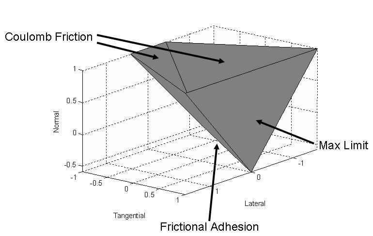
The picture below shows what the contact constraints were assumed to be for the 3D case.
Basically, lateral forces decrease the amount of adhesion that can be achieved and they do so linearly with "mu".
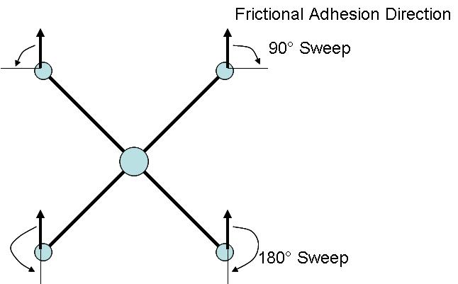
Below is the geometric model for this analysis. Most important to note is that the front and rear foot orientations will be "swept" through different angles.
The paremeters for this model were the following:
- Mass = 20 grams
- Front to Rear Foot Contact Distance - 20 cm
- Side to Side Foot Contact Distance - 20 cm
- h = 2.5cm
- mu = 1
- alpha = 1/sqrt(3) (30 degrees)
- Fmax = m*g
Stability
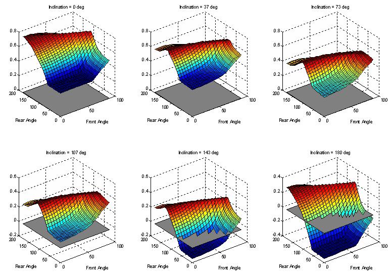
We can then perform the optimization analysis that will determine what the best internal body forces will be to achieve contact forces that are furthest away from violating any of the contact constraints. Below is shown what the "safety margin" is as a function of front/rear foot orientations for a sampling of different surface inclines between 0 and 180 degrees (fully inverted). The "safety margin" is the minimum distance that all the feet are from violating any one of their respective contact constraints. In this sense it is similar to the amount of perturbation that each foot could withstand before slipping or peeling.
For each surface incline, we see that there is a curve in front/rear foot orientation space of constant safety margin.
This curve shifts at different surface inclines.
Also shown is a plane at a safety margin of zero, below which, failure occurs.
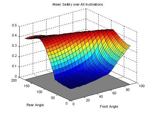
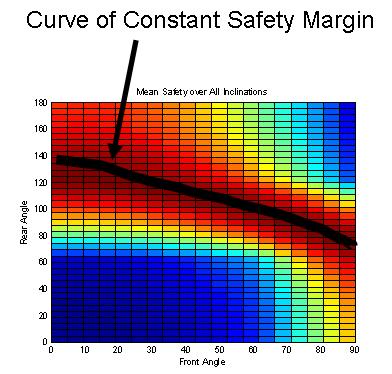
We can also look at the average "safety margin" over all surface inclines.
Again, we still see a curve in front/rear foot orientation space along which the safety margin is constant.
If we were concerned about failure equally at all inclines, and we had to pick one
nominal foot orientation then this information would help to choose the best set of foot orienations. Alternatively (and probably more realistic), we could weight each incline depending on how close we are to failing on that incline. It is also important to not just look at the maximum value of safety margin, but how susceptible it is to small changes in the front/rear orientations. The curve of constant safety margin falls off steeper at different points.
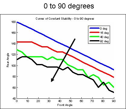
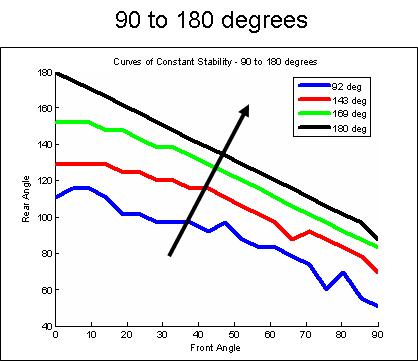
The next two plots show how the maximum safety curve changes as a function of incline angle.
At 0 and 180 degrees of incline, the feet tend to be oriented in direct opposition to each other (0/180, 45/135, 90/90).
Gravity then seems to bias the feet so that they both orient more towards the direction of gravity.
At 90 degrees, gravity can "pull" the feet in such a way that it generates more adhesion force at the feet, if they are oriented properly with the gravity vector.
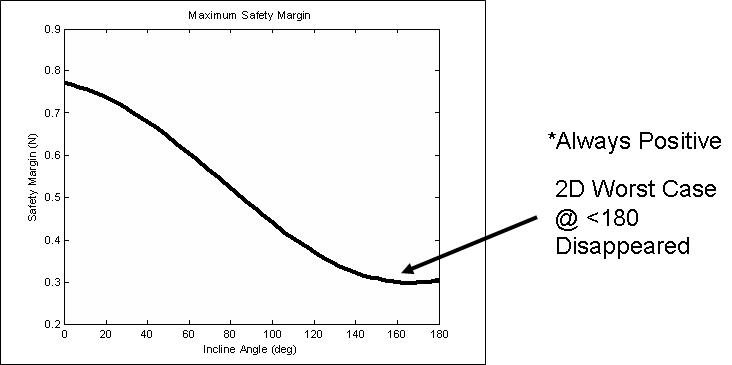
As in the 2D case we can also simply look at the maximum stability that can be achieved as a function of incline over all orientations.
Stability decreases overall as incline increases, not surprisingly.
However, for the parameters used in this analysis, the robot/animal can be stable over all inclines between 0 and 180 degrees given the proper front/rear foot orienatations.
We also no longer see a worst-case at an angle less than fully-inverted as we did in the 2D case.
This may be because we no longer have a binary choice between aligned and anti-aligned but can sweep the foot orientations through a continuum of angles.
Contact Forces
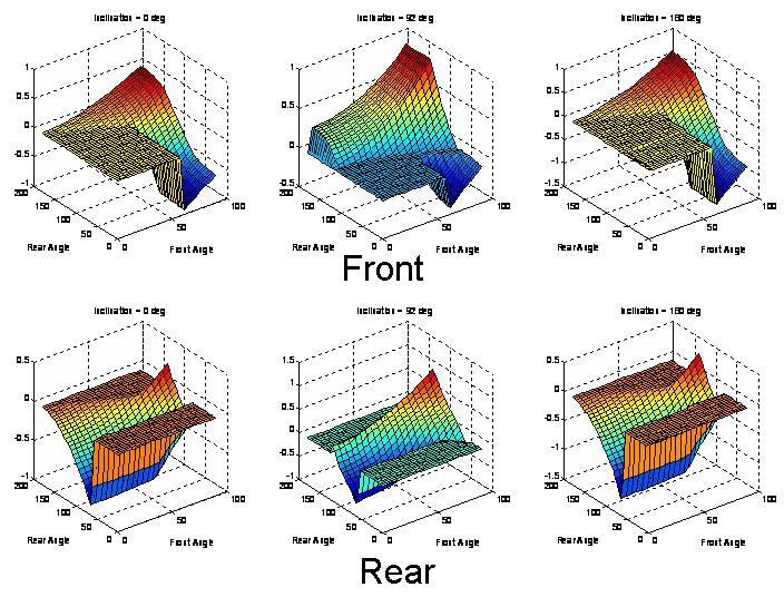
Finally, we can look at the contact forces directly and see how they are related to foot orientations and incline.
This plot shows the Lateral contact forces for the front and rear feet at inclines of 0, 90, and 180 degrees.
In general, the lateral forces tend to be small at points in orientation space that match points where the safety margin is a maximum.
By design, the contact constraints assumed that lateral forces decrease the amount of adhesion that can be generated.
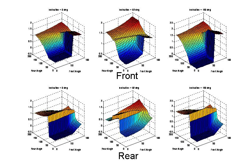
This plot shows the Tangential (frictional adhesion direction) contact forces for the front and rear feet at inclines of 0, 90, and 180 degrees.
We see that the tangential force tends to always be positive in order to generate the necessary adhesion forces for the model to stay on the inverted surface.
However, it is not always a maximum at points in orientation space that match points where the safety margin is a maximum.
Thoughts
The analysis (both 2D and 3D) shows that different foot orienatations will be better for different inclines.
So, the question is, do climbing animals follow any of these predictions?
Well, the model predicts that the rear foot should be rotated 180 degrees (reversed) on level ground, which we know not to be the case.
One thing that the analysis does not consider, is the effort required to maintain the foot orientation and the effort required to maintain the internal body forces.
So, it may be that the predicted trends only appear when it is necessary in order to not fail, i.e. do just enough not to fail.
As a general trend, the analysis predicts all of the feet should be oriented somewhat inwardly in order that they can all pull against each other in the frictional adhesion direction, thereby generating the maximum amount of adhesion.
This follows directly from the contact constraints that were assumed.
Is this actually the case? to what degree?
The not-so-intuitive trends are the existence of curves of constant safety margin in front/rear orientation space and the way in which they change with angle of inclination.
This would say that there are a number of different orientations that are equally good for a given incline angle (but why?).
Maybe the 3D contact constraints are not capturing the true behavior.
Inclines around 90 degrees tend to bias the curves so that the feet tend to be more oriented in the gravity direction.
In this area, gravity actually helps the feet generate adhesive forces, but only if they are oriented such that the tangential direction is in the gravity direction. Away from 90 degrees (0 and 180), there is no bias, so the feet tend to be as opposed as possible to each other.
 RisePrivate Web>StaticModeling? >FrictionAdhesionOptimization (18 Apr 2006, DanielSantos? )