new web: http://bdml.stanford.edu/pmwiki
TWiki > Rise Web>TWikiUsers > TaylorCone>TaylorsSummerBlog (27 Aug 2008, TaylorCone? )
5-- TaylorCone? - 23 Jun 2008
Summer Blog
Week of June 23rd
Monday, June 23rd
- Went through Solidworks Online Tutorial for designing a part and an assembly. The program seems very straightforward and I feel comfortable using it even with this little experience.
- Began reviewing SDM Tutorials and Notes from SDM.
- Observed use of Haas machine by Ivan and Alan. They walked me through the main steps of the process and I am confident that I could run the machine.
- Began reviewing ZMan information from ZMan WebHome
- Discussed perching project with Alexis. He gave me several links to more information on the project as well as some videos and a pdf on Compliant Microspine Arrays.
Tuesday, June 24th
- Read paper entitled Scaling Hard Vertical Surfaces with Compliant Microspine Arrays by Alan, Sangbae, and Mark. This clarified much of how the toes and feet work on a fundamental level. Reading it also got me thinking about the feet more comprehensively.
- Alexis explained the perching project to me extensively and we talked about the next steps for the project. He outlined 5 major areas:
- 1) Establishing controls for roll and altitude (at this point the gyro doesn't receive roll information and we don't have any altitude sensors)
- 2) Another sensor to detect when the aircraft is nearing a wall. It could be based on a laser which may allow for broader abilities or it could be based on sonar
- 3) Designing a new foot/toe spine specifically made for the aircraft. It would need to be light and small yet strong enough to support the aircraft. We would also like it if the foot was modular so the aircraft itself wouldn't need to be modified to great extent in order for the feet to be attached.
- 4) We need to design a suspension system that accounts for whatever horizontal velocity exists when the aircraft hits the wall. Too much impact could be dangerous to either the feet or the body of the craft. This suspension system could be integrated with the foot, resulting in a toe/foot/suspension unit, or it could be an independent step between the body and the foot.
- 5) We discussed looking into working with micro planes. This would be best to investigate once we reach some of our goals for the current plane, however.
- Since going after all of these at the same time would be over the top, I plan to pursue work on designing the foot/claw and suspension systems. Although I would certainly consider the other goals, at this point I feel like my skills would be best put to use doing that. I have done some coding before but not in C (but C++ and objective-C), so perhaps coding for the control of the roll would be a formidable task for me. Alexis and I plan to discuss our actual goals and lay out some sort of timeline soon.
- Tonight, I plan to further read the two books I checked out from the library on flight in order to better understand the dynamics involved in the perching maneuver. The books are Fundamentals of Airplane Flight Mechanics by Hull and Flight Dynamics Principles by Cook. Additionally, I will read a paper from MIT on hovering of single propellor planes entitled Hover, Transition, and Level Flight Control Design for a Single-Propeller Indoor Airplane and try to understand as much of that as I can. There is another paper that Alexis sent me that discusses perching and climbing feet of birds which I will browse as well. Finally, if I have time tonight, I'm going to try to brainstorm some ideas for new feet/claw systems as well as possible suspension scenarios.
Wednesday, June 25th
- Went through the tutorial of SDM and Basic Unigraphics. I hit a few snags but everything is clear now; Alan helped me through it when I needed it. I plan to practice some more tomorrow to try to get the hang of it more consistently.
- Brainstormed ideas for the suspension system and possible forms of the foot/claw assembly. I did some Googling and read some stuff on landing gear, biomechanics of the lower limb joints, and general shock absorption techniques. I didn't have too many ideas, but I did think of one possibility: if the shock absorption system absorbed the impact quickly but recoiled very slowly (i.e. pushing back outward from its compressed state), the force of it extending could be used to help give the feet a better grip. From messing with the multidirectional foot on the brick, it is clear that traction is better when more force is applied on the foot toward the surface. If we could make a suspension system that had slow recoil we could take advantage of that for better attachment. Also, with some thoughts about how knees absorb impact, I thought perhaps we could use a similarly flexible system on the robot. I didn't do any drawings but I'll look into that tomorrow. I also thought about making a new toe designed specifically for the perching robot, but I want to discuss that more with Alexis and Alan to get more of an idea of where we stand now and what the current designs are like.
Thursday, June 26th
- In the morning I started thinking about and drawing up some possible suspension ideas. The first idea mimicked the knee joint, with basically a single hinge joint and a spring. I figured that this configuration would allow for some damping as well for the extension, so that's good. If we were to use the impact force to our advantage, I thought of some ideas on how to use the recoil from the impact for the grasping motion of the hand. For instance, if a rod was attached to the upper part of the joint limb, it would push down on impact, opening the claws if positioned correctly, and then during the recoil the claws would slowly come together, grasping the wall.
- I helped Alan and Ivan with part of the toe manufacturing process. I laid the fishhooks into the mold with Alan and then observed them make and pour the plastic onto the wax block. The process seems pretty simple so I think I could get the hang of it pretty quickly.
- Alexis and I discussed our plans for the next week or so. In the next week, Alexis hopes to have the roll problem under control, and I will work on creating a new foot/ankle assembly so we can test the plane with the latest generation of the toe. I worked on a new plane-specific side plate for the feet and I think I'm pretty close to a final design. After my initial design, Alexis suggested that I make a rough prototype out of old side plates and wood to get an idea of what design I want to use. From there, I can make sure that I put holes in the right places in the new side plate before we go through the manufacturing process. I got a prototype basically finished and realized that I needed to make a couple more holes in the right places.
- Tomorrow I plan to finish designing the side plate. I'll look at the prototype a little more to make sure the side plate is optimized and then go for it. Alexis also suggested that we build the new RC plane for future tests just so we have it ready whenever we need it so that might be another project.
Friday, June 27th
- Finished the design for the new plane-specific foot side plate. Alexis and I checked out my first design, he pointed out some things that needed to change so I fixed those and the design is ready.
Saturday, June 28th
- Moved the side plate design from Solidworks to Unigraphics and on to writing the HAAS file. This was the first time I'd gone through the actual process mostly on my own, so I was learning along the way. I feel pretty good about it and I think I could probably do the process again without needing assistance.
- Alexis and I cut a wax block on the HAAS for the side plates and poured the plastic for it so it would be ready to drill holes into on Monday.
Week of June 30th
Monday, June 30th
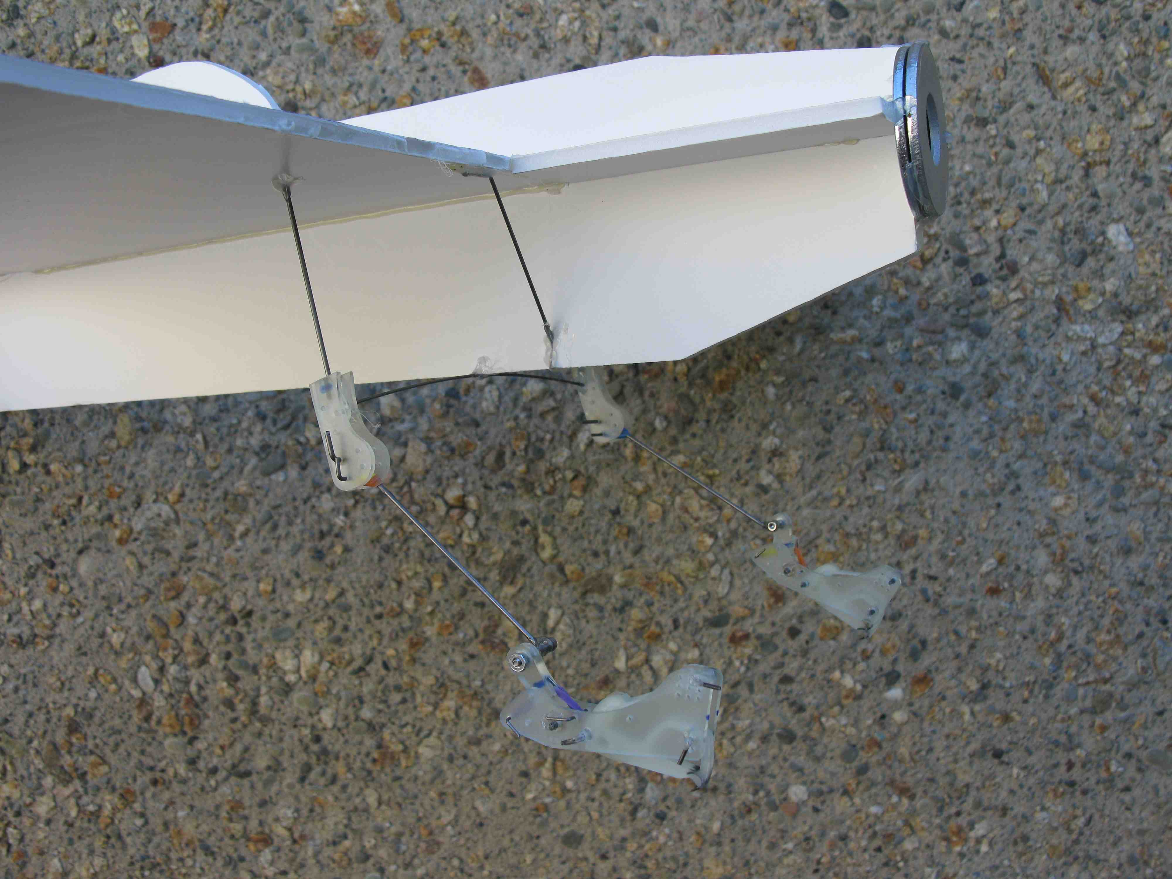
- Finished the new side plates for the plane feet. We drilled the holes in them and then I made the feet. Each foot has 5 toes which will be more than enough to hold the weight of the plane (~150g for each toe x 10 total toes = 1.5kg, plane is only ~320g). I began making the ankle joint as well, which will allow the foot to pitch forward and backward. This motion is necessary because if the plane approaches the wall at some angle we need the feet to be able to bend a little in order to grasp the wall.
- Also took a look at Alan's ankle design for RiSE and checked out the ankles that are on RiSE now. An ankle with freedom and flexibility like that one would be great for the plane, so I'll keep that in mind for when we design the more complex ankle joint for the plane.
Tuesday, July 1st
- Completed the ankle of the new feet for attachment to the plane. It was important to have a specific stiffness in the ankle - compliant enough to be safe for the plane to hit the wall, but stiff enough so the toes would flex a little as well.
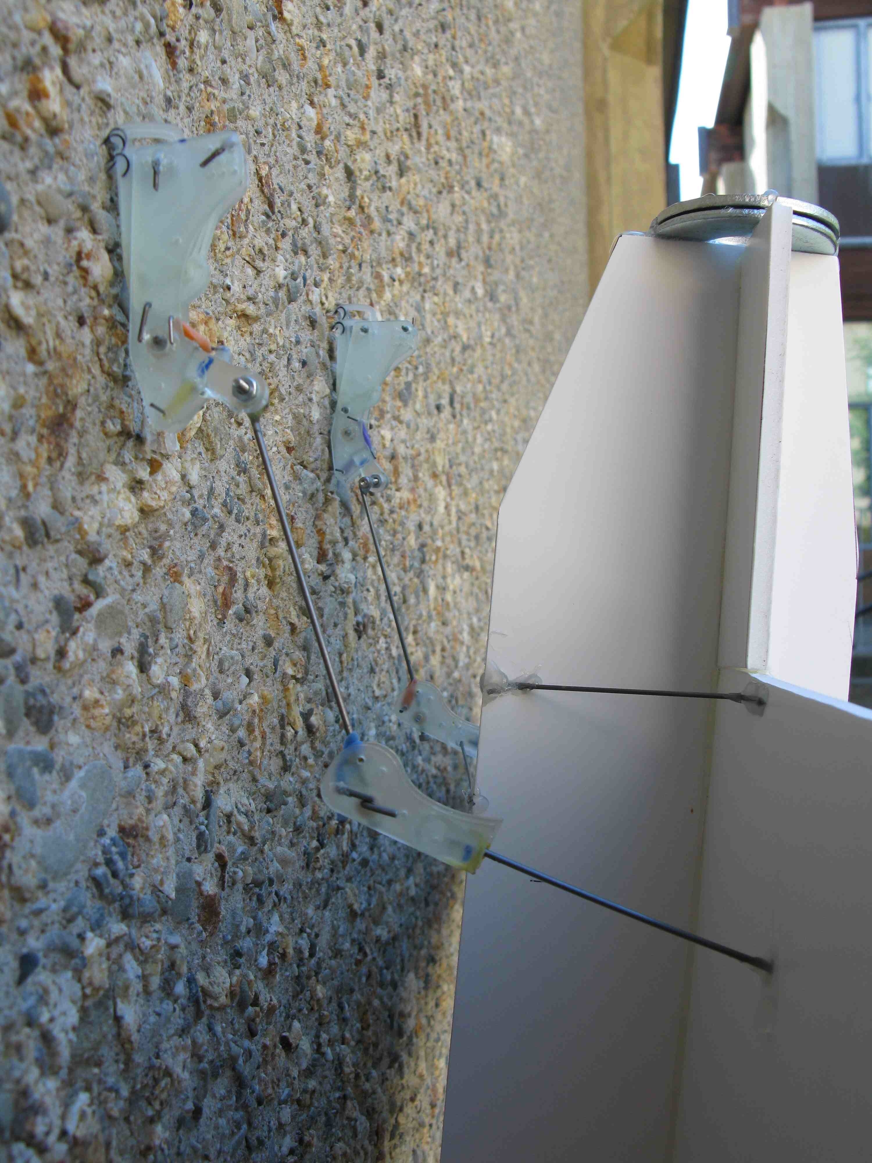
- Alexis and I built a mock plane out of foam core board - for testing, we wanted a platform that was roughly the same shape and weight of the real plane but less delicate. We attached the feet to the mockup and started throwing it against the wall. It performed surprisingly well. Even with a pretty good amount of horizontal velocity the plane would still grab on with enough force to hold itself. The leg design that is on the plane now and we mimicked on the mockup had a good amount of suspension ability, although there was no damping and it basically acted as a spring if there was too much horizontal velocity. From the testing, a few things are clear: the number of toes we chose (5 on each foot) is more than enough the hold the plane, but not too many to be reasonable. There need to be enough toes so a good number can find irregularities in the wall, so 10 is a pretty good number. Also, in some tests the plane held on when only one of its feet was attached; another benefit to having more toes than are absolutely necessary. The only major problem in the testing was that the hot glue didn't hold very well to the metal legs, so after a few impacts the glue would come loose and the legs/feet would rotate freely.
- Some other things to keep in mind for future testing: with this leg design, on impact the legs splay outward, rolling the feet outward as well; there is no damping in this design, and that will be added later; we can put the feet at any orientation with respect to the body of the aircraft - parallel to the body, angled downward a little, etc - which would allow for optimization of impact grabbing.
Wednesday, July 2nd
- Alexis and I continued testing the mockup airplane with the feet attached. We ran some trials of throwing it against the wall, and they were actually pretty successful. As long as the plane was thrown from close enough to the wall, it stuck extremely well. There were some problems with shock absorption and damping, to the effect that sometimes when the plane hit the wall the legs bent a little and then when they bent back, they launched the plane off the wall. So that is one major area for improvement. This result occurred in both the horizontal and vertical directions. The horizontal one will require more damping to fix; the vertical one could either use more damping or, if we wanted to go this route, giving the foot an opposable claw would hold it on better. We made some videos of our trials so we could study the dynamics more closely. Over the next few days I'll be away, but I'll study the videos and take notes, hopefully resulting in some ideas on how to improve the legs and feet.
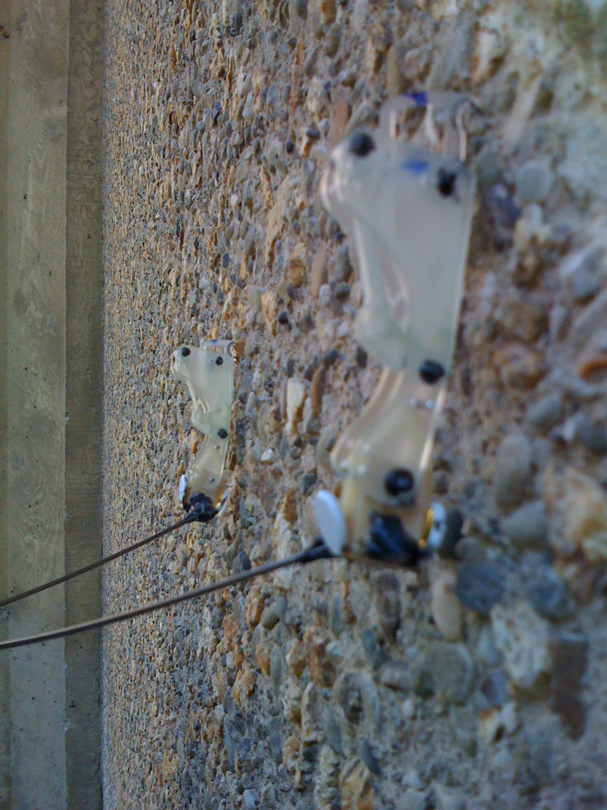
- The Perched Plane:
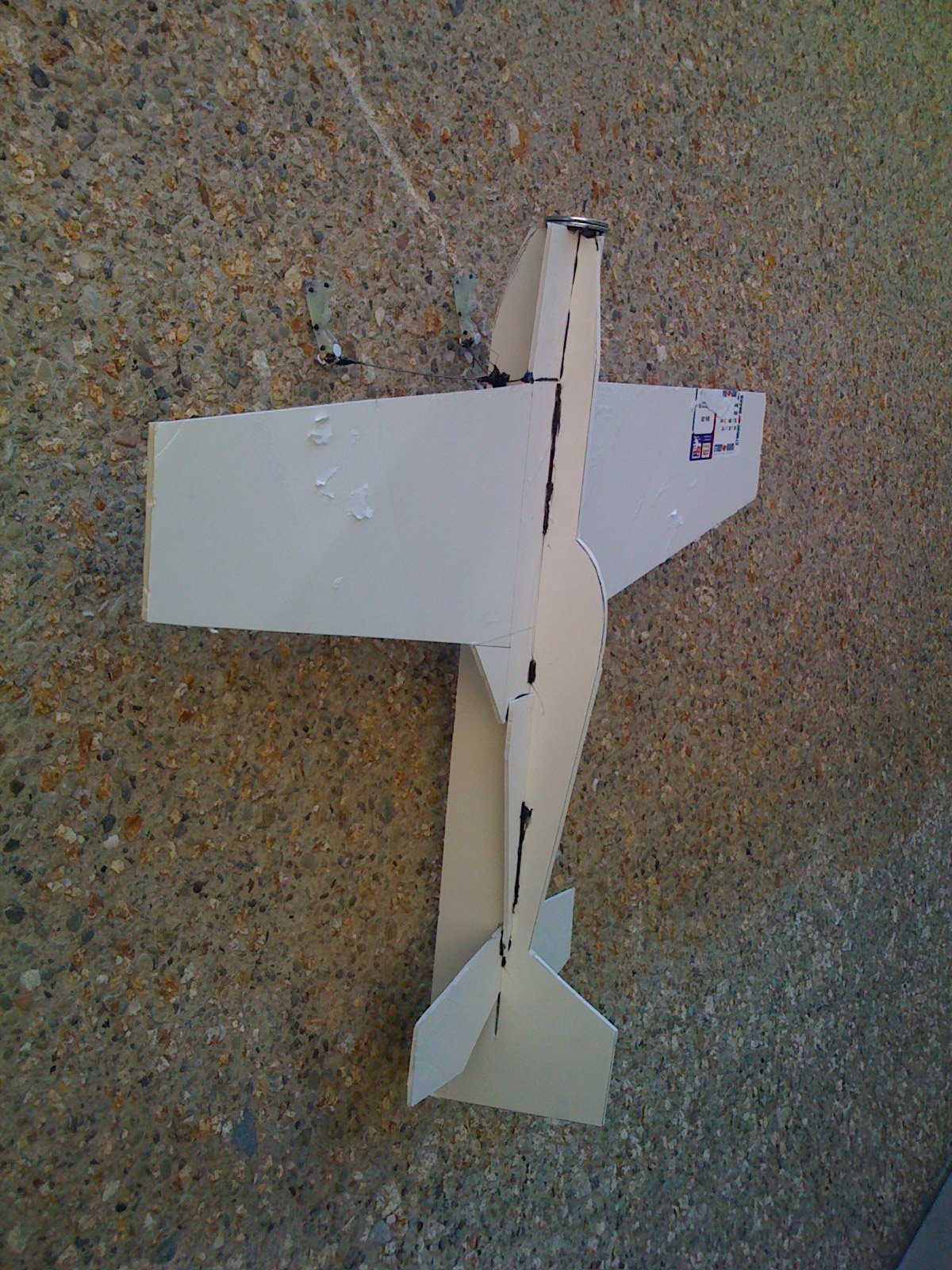
- A Closer View:
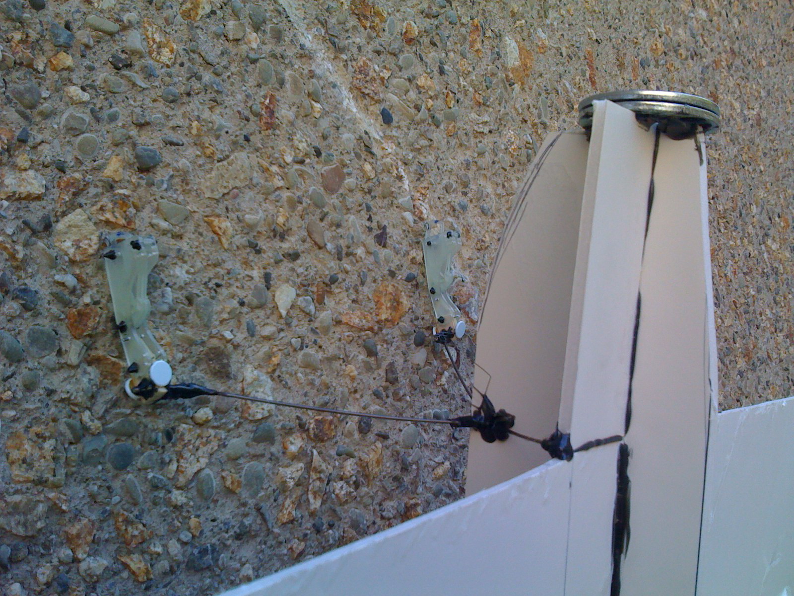
- A Close-Up of the Feet:
4th of July Weekend
- Studied the video of Alexis and me throwing the dummy plane at the wall.
- Sometimes the plane rolls, causing it to hold on with only one foot. This effect could be lessened if some sort of supports were placed on the wings, pointing toward the wall. This way, the plane wouldn't roll enough for the one foot that is engaged to come off.
- Obviously a major problem is the suspension and the dampening thereof. We need to worry about the horizontal direction but also the vertical direction. In the final version we will surely use a more complex leg and foot designs, and we must factor these characteristics into them.
- The plane attached best when it struck the wall at or very near the apex of its arc. This must be considered when designing the control system. There should be some downward momentum so that the feet engage (if we use single-directional feet) but not so much that it causes the plane to bounce off the wall.
- There needs to be some amount of stretch (with damping) in the legs. In one of the clips the plane is falling and it grabs onto the wall with considerable downward momentum and the leg stretches. A safer stretch mechanism would be good to implement.
- Expanding the feet into a claw design might work better for holding on, but the process of engaging the claws to attach to the wall will be more complicated than single-directional feet. There will need to be some sort of mechanism that pulls the claws inward to engage them in all directions.
Week of July 7th
Tuesday, July 8th
- I looked at the good resolution movie that Alexis made in Final Cut and made some more observations. We had a brainstorming session where we discussed our observations from the clips and put forward ideas for how to resolve any issue we saw.
- Sometimes when the foot hits at a certain angle, it bends backward and therefore does not engage at all. After some discussion, we decided that the best way to resolve this would be to make a foot that attaches to the ankle somewhere in the middle of the foot rather than at the back end. This would mimic the human foot, having the ankle slightly forward which would create a sort of "heel" for the robot. This would help eliminate the possibility of the foot pitching backward and staying in that position.
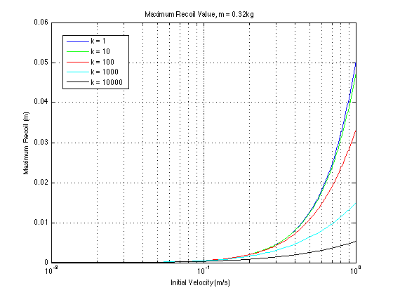
- We did some math on the dynamics of the incoming plane. We want to find an initial velocity range that will NOT allow the plane to bounce back upward past the zero position on impact. We modeled the legs as springs and came up with an equation of the form ma = -mg - kx. Solving this allowed us to find an equation for position as a function of time. I continued some math to find the time at which the first maximum recoil occurs. We then plugged this time value into the equation for x to find the maximum value of x for a given initial velocity, spring constant, and plane mass. Tonight, I plan to mess around with the numbers and see if I can spot any trends.
Wednesday, July 9th
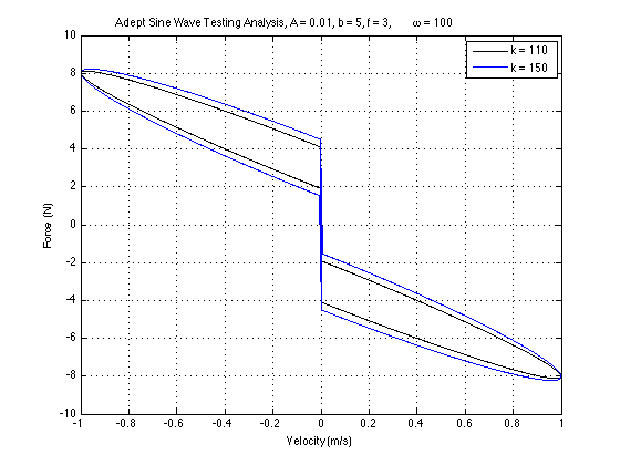
- Continued studying the kinematics of the approach and landing. The equation we found for the vertical displacement as s function of time after impact is: x(t)=A*e^(sqrt(k/m)*i*t)+B*e^(-sqrt(k/m)*i*t)-(mg)/k where A and B are constants determined by the initial velocity, m, g, and k. Further, we had to find the time at which the first peak of displacement (maximum recoil) occurs. The formula for this is: t = sqrt(m/k)*arctan((v0/g)*sqrt(k/m)). Some of the plots we made are shown below. The spring constant seen in the plots is the constant for the leg of the plane. The recoil distance refers to the amount the plane "bounces" back up after impact causes the springy legs to extend.
- Keeping Mass Constant, Changing Spring Constant:
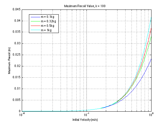
- Keeping Spring Constant Same, Changing Mass:
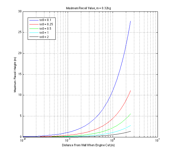
- Studying the Effect of Different Initial Velocities on the Maximum Recoil versus Distance From Wall when Engine is Shut Off:
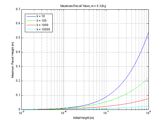
- Given an initial height, we wanted to find the maximum recoil for different spring constants. We made plots with various masses and found that there is a negligible difference within the range of reasonable masses (0.1kg-2kg):
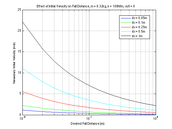
- We also wanted to find what initial velocity is necessary to have a certain desired drop distance. In this simulation air resistance is not considered. For small distances this won't be a significant problem, but for larger distances it must be considered. From this plot it is evident that we need to have the peak of the plane's trajectory relatively close to the wall if we are to keep our initial x-velocity within reason.
- Started brainstorming ideas for a new foot design, probably with a heel integrated into it. This will help eliminate the possibility of the foot pitching backward about the ankle joint. As it is now, the ankle is at the very rear of the foot, so any moment that exists will be about that axis. We want to make a heel on the foot so the ankle can be moved forward and any moment about it that would otherwise result in a disengagement of the foot will be counteracted by the heel.
Thursday, July 10th
- Started redesigning the side plate for use on the next generation of foot. Taking cues from the problems evident in the testing video, we chose to move the ankle attachment point farther forward on the foot so there is a heel. The front of the side plate remains the same, but the rear has changed a little. The bottom of the side plate at the back is lower so that it definitely touches the wall instead of the back of the toe.
- After making a prototype foot with the ankle joint in the new position, a few more necessary changes became evident. We intend to have holes in the plate for studs to go through to act as stops for the ankle. Also, we chose a couple different locations for studs for the rubber bands: two are symmetric with respect to the ankle pivot point and two are farther away to cause a larger moment. When we make the feet we can experiment with the different placements to determine which is optimal.
Friday, July 11th
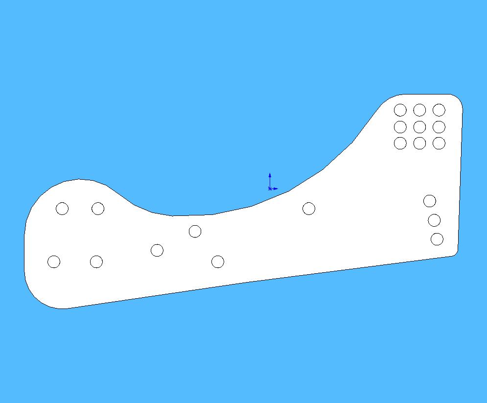
- Finished designing the new side plate and cut the mold in the wax block on the HAAS. The new side plate is a little longer (a few millimeters) and the back end of it extends farther down (toward the wall when perched) so it can act as a heel. The ankle joint has been moved forward to act as a pivot so the heel can counteract any backward pitching motion. We chose to make two new side plates: one with a slightly lower heel than the other to find out which would be better for holding onto the wall. The old one and both the new ones are shown below:
- The first version of the plane side plate.:
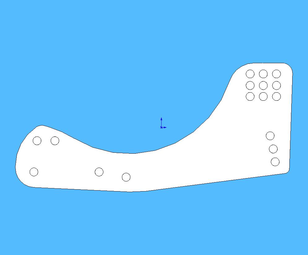
- The second version of the plane side plate, with the ankle connections moved forward and slightly lowered heel.:
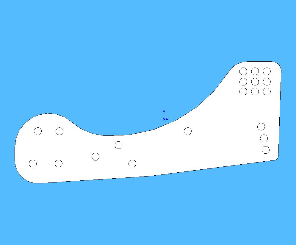
- The second version of the plane side plate with lower heel.:
Saturday, July 12th
- Poured the plastic for the side plates. They'll be ready for Monday!
Week of July 14th
Monday, July 14th
- Drilled holes in the new side plates and made the new feet. I experimented with different rubber bands in the ankle as well as different placements for them. I thought maybe at some point we could have the ankle piece have some soft plastic or rubber which could be used as a spring for the ankle, but I'm not familiar with the properties of that stuff (i.e. whether or not it works well in such situations). Will continue to experiment with the different ankle designs tomorrow.
- Alexis came up with an idea for damping in the ankle joint that consists of adding friction using sorbothane. I'll attach this to the foot tomorrow to see how it works.
Tuesday, July 15th
- Continued testing ankle designs and found one that is pretty good. It consists of using the small (1/8") rubber bands attached at one end to the ankle piece and at the other end to the rear stopper on the foot. This design is compact and minimizes the use of larger rubber bands, which is good. After testing, however, we found that with two of these rubber bands on each foot the ankle was too stiff.
- Through testing, we also found that the new foot design with the heel may do more harm than good. Because the heel protrudes more toward the wall in the new design, it may actually hinder the claws' ability to grab onto the wall. This resulted most commonly in a tendency of the plane to just fall down the wall, dragging the feet because the claws were never able to engage. To combat this, I think the best thing to do is to shave off some of the heel and try again. Having moved the ankle toward the middle of the foot I think will make a big change anyway; maybe one change at a time is best to see what effect it has. It is unclear at this point whether the problem is mostly the heel or the stiffness of the rubber bands.
Wednesday, July 16th
- Continued testing of the new design by throwing the dummy plane at the wall. We found some problems with the new design: the heel was too low so it was getting caught on protruding surfaces of the wall, causing the foot to pitch backward and disengage; the pin that was serving as a stopper for the forward pitching of the foot was actually hindering the foot's ability to grab the wall; the rubber bands we used weren't optimal in terms of stiffness. I shaved some plastic off of the bottom of the heel, removed the rear stopper pin (and added opposable rubber bands), and used the older rubber bands that have the more desirable flexibility. I think we've basically fixed the problems that were introduced with the last version of the feet and we'll continue to test tomorrow.
- Alexis has the plane hovering at this point, so as soon as tomorrow we may attach the current feet to the actual plane and test the hover-to-perched maneuver. This is very exciting!
Thursday, July 17th
- Went through various designs of the foot, repositioning the rubber bands and pins until we found a good design. The design we had had the larger rubber bands attached externally and they were rather vulnerable. The new design involves internally connected rubber bands, attached to the ankle piece by a pin parallel to the side plates and at the other end attached to pins going through the side plates. We used the smaller orthodontic rubber bands which are stiffer, but since they are being stretched less distance, the ankle is not too stiff.
- We also added damping to the ankle joint by gluing sorbothane to the side of the ankle piece, increasing the friction between it and the side plates. There is a noticeable difference; when the foot is pitched backward, it doesn't spring back as much as it did without the damping. Another (unforeseen) benefit of having the sorbothane is that it allows for slight but noticeable movement of the ankle piece around the pin about which it rotates. We used a smaller pin than before, so there is a little wiggle room for the ankle piece, and since the sorbothane is rubbery, there is some movement but it is damped as well.
- Had a brainstorming session to think about the best leg designs. We came up with various ideas, but the frontrunners were: a birdlike leg having a sort of "elbow" allowing it to bend in that direction; a semicircular arc, starting under the wing and ending directly in front (essentially like the elbow but rounded rather than pointy); cross-legs starting at the rear support struts on the plane and going through the front ones, forming an X so the feet would be farther forward (toward the prop) than they are now; a 2-spring system forming a sort of quadrilateral. We aren't sure which is best yet, but we like the circular idea. I'm going to do some more research on that design and hopefully get a better understanding of the stress and deformation of such shapes.
Friday, July 18th
- Today mostly consisted of testing the plane and perfecting the new foot design. We came out with a very successful product; at the end of the day I tested the plane a little (by throwing it at the wall) and it stuck very consistently. I threw it at different trajectories and there was considerable wind at some points, but the plane was successful nonetheless. The next step would be to see what the most significant factors are in the success of this design. We've dealt with quite a few factors (stiffness of rubber bands, heel design, ankle design, rubber band placement, etc.), so it would be good to identify those that affect the outcome the most.
- Outlined design ideas for the next generation of ankle and side plate pieces. We decided that the ankle piece should have (in addition to the holes already present) space cut out for the sorborthane dampers, a hole drilled perpendicular to the current holes on which to put the rubber bands, and an indentation that fits the nuts so we can screw on the feet and avoid rotation. Also thought about the side plates, and the most important changes to make were to remove the heel and to add material under the toe pivot pin so the toes don't drag on the wall.
Week of July 21st
Monday, July 21st
- Alexis and I talked a little about our next plans for the plane. As mentioned above, an important remaining step is to create an optimal leg design; one that is strong and stiff but can absorb some impact and has some damping is our goal.
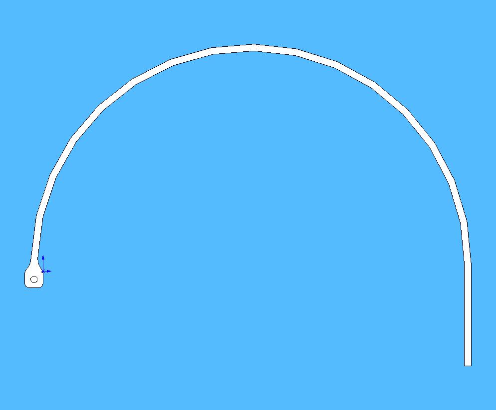
- I started making a circular leg design idea in Solidworks. We decided it needs to have an elongated end to attach underneath the plane's wing as well as an expanded width at the other end so we can drill a hole through it to attach to the feet. The current design is 2mm wide (in the radial direction) and 5mm across. We figured that this will allow for enough strength while maintaining flexibility (I = 1/12*b*h^3). A snapshot is shown below:
- The newest leg design idea.:
Tuesday, July 22nd
- Cut and poured the new semicircular leg design.
- Started thinking about the next foot design.
- The side plates are pretty good as they are, but could use a couple minor changes. First, "as they are" means as they are after we shaved off the heel we added on in the latest generation, so we'll have to eliminate the heel. The feet are working very well right now, so even though we shaved away plastic until it looked right and it was rough, it would probably be fine to model the new design off of the current ones. Another possible improvement is to lower the side plate near the pin where the toe pivots. This would eliminate the possibility of any part of the toe (the soft part especially) being damaged by dragging down the wall.
- The ankle pieces are perfect in terms of size, but we're going to customize them a little. Since we added some sorbothane to produce damping when the ankle pivots and had to sand down part of the ankle, we're going to have that part cut out in the new design. Also, to avoid rotation around the tip of the leg, we've been using nuts to tighten the joint; to improve this we're going to cut out a section of the ankle piece so the nut can go inside it and eliminate rotation. In order to achieve these characteristics on both sides of the ankle, we'll have to make two halves and then glue them together afterward.
- Read a little in Fixed and Flapping Wing Aerodynamics for Micro Air Vehicle Applications. I wanted to learn a little bit more about the other side of the project, i.e. the plane design and dynamics. I know it's ambitious to think about right now, but it would be awesome to expand this project to a flapping-wing vehicle (ornithopter).
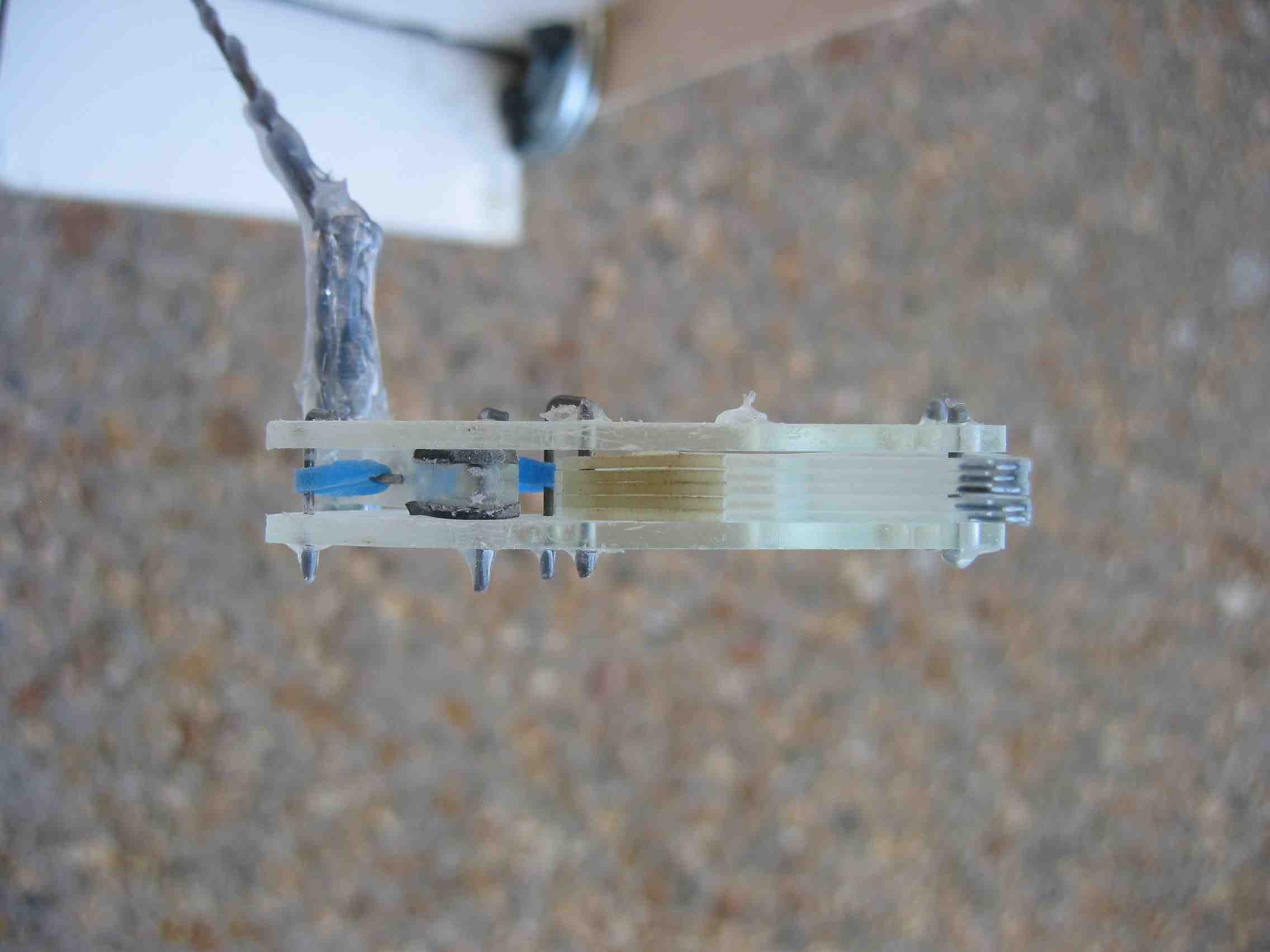
- A view of the newest foot design:
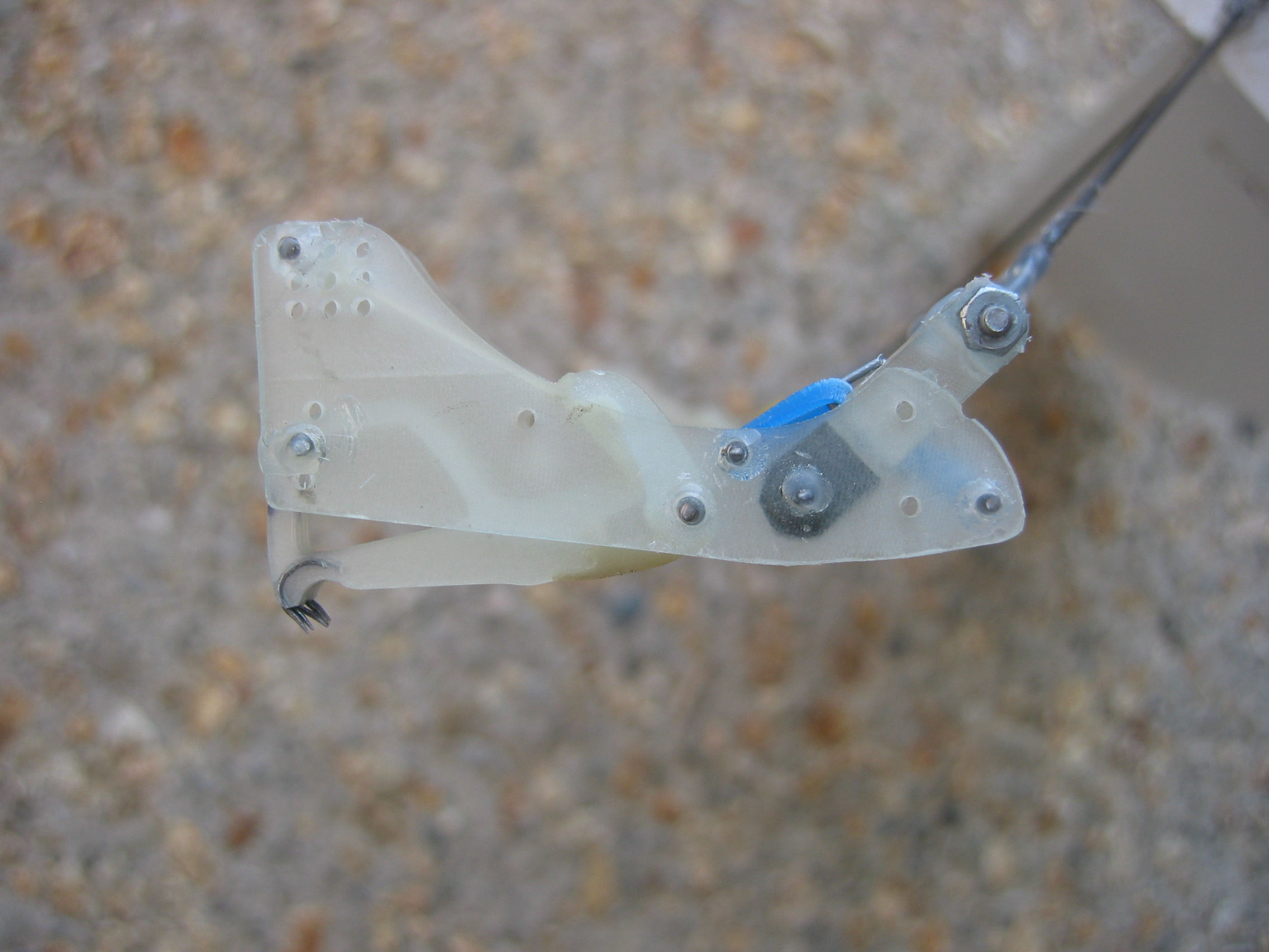
- A shot of the foot in action...or lack thereof:
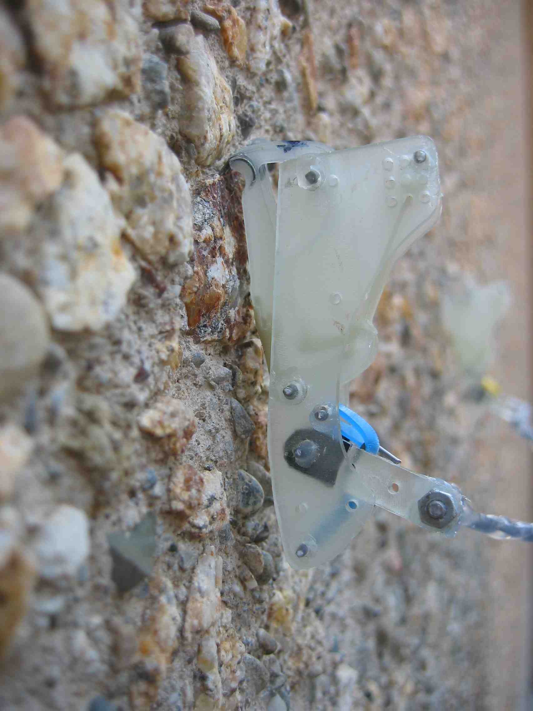
- A look at the underside of the foot. You can clearly see where we added sorbothane (black) to increase friction during pitching and therefore produce damping.:
Wednesday, July 23rd
- Didn't make it in today...had a run-in with a raccoon on 280 at 1:00am and didn't get back to my room until 8:30am...
Thursday, July 24th
- Designed a new version of the side plate. We added some material under the ankle joint, solving the problem of dragging toes, as well as taking away the low heel that we had on the last version. I cut and poured the side plates so they'll be ready for tomorrow.
- Took out the semicircular legs. They have a pretty good stiffness and they may work pretty well. We might attach them to the plane tomorrow and see how they perform getting thrown at the wall.
Friday, July 25th
- Drilled holes in and took out the new side plates. They look like a good design, so I'm excited to see how they perform on the wall. We compared them to the ones we have attached to the dummy plane right now (which are working very well), and the only major difference is that the new side plates have more material under the ankle joint. We hope that this will help engage the spines and keep the toes pitched forward.
- We decided that we needed some more toes, so I milled them and poured them so they could dry over the weekend. With the new toes, we can make new feet and see how the new side plates work!
- Examined the stiffness of the semicircular legs further. Alexis added some Kevlar to one of them to see how it would affect its flexibility. Overall, there was a noticeable difference but we weren't sure if realistically it would change the behavior of the leg. We like the idea of the leg, however, so we'll probably attach the new feet to them and give them a try. We realized one problem with the semicircular design: when compressed, the ends tend to bend inward, resulting in an angled (rather than vertical) orientation for the two ends. If the legs were concave up (which we were thinking), this would cause the feet to be pulled away from the wall and the leg would touch the wall below the foot. If the legs were concave down, this may actually be beneficial. If the end gets pushed inward, it will cause the foot to dig more into the wall. These are only thought experiments at this point, however, and we intend to conduct full testing before jumping to conclusions.
Week of July 28th
Monday, July 28th
- Took the new toes out of the mold and cut the excess plastic off the spines. Making toes is a long and demanding process! These toes are the new design (version 9, evidently) given to us by Alan and Ivan. They seem to be very good, although the difference isn't exactly significant.
- Built the new feet, using the new toes as well as the new side plates and the new ankle pieces that Alexis designed. The new ankle pieces have soft material in the joint where it connects to the foot which acts as a damper during rotation. The new feet look good although we haven't connected them to legs yet.
- Made some more semicircular legs. I sort of messed up the ones we made before by taking one out early so they weren't the same shape exactly (oops!) so we decided to make more to test with. Unfortunately, the design may not be perfect; today I conducted some simple testing with the concave up and concave down orientations and neither were necessarily preferable.
- Concave up: when compressed, the foot pitches backward, pulling it away from the wall. When weight is put on, a similar thing happens. (Bad!)
- Concave down: when compressed, the foot pitches forward, digging into the wall pretty well. When weight is put on, however, the foot pitches backward and disengages the spines. (Bad!)
- So either orientation isn't great in these preliminary tests, but we'll see when we attach them to the plane how they work!
Tuesday, July 29th
- Took out the second round of semicircular legs. We might attach them to the plane, but with more thought it seems like we've sort of moved toward legs with an actual joint where it can bend. Alexis made one of those, consisting of two metal rods connected by a joint similar to that of the ankle on the feet. We'll attach them to the plane tomorrow and see how they work!
- We also plan to make another dummy plane tomorrow so we can have two different sets of feet attached and testing at once.
- Tomorrow we plan to also learn the Adept so we can use that for more controlled testing of the plane. We also might use it for testing suspension systems by applying a force and reading the reaction forces when the suspension is compressed and extended.
- A shot of the entire leg assembly.:
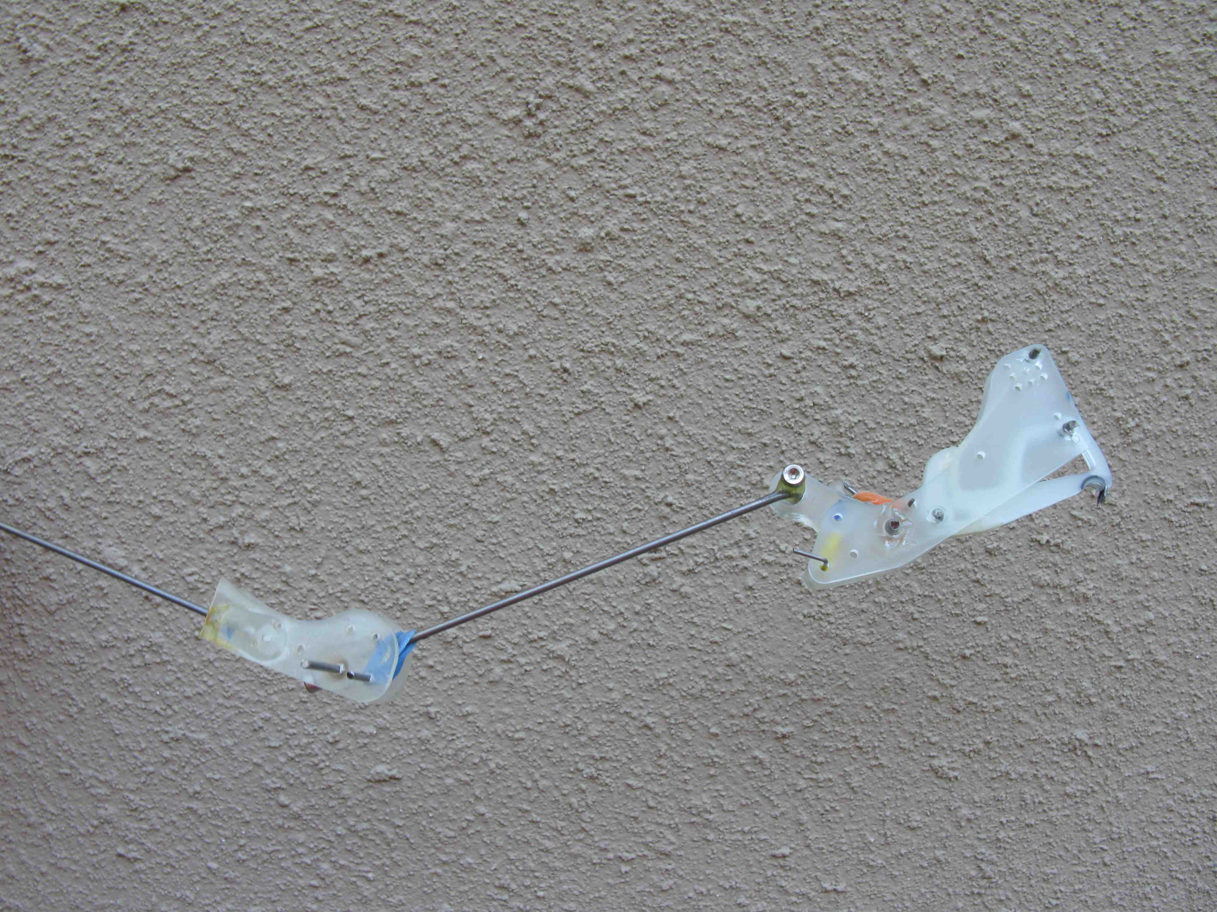
- A bottom view of the foot and ankle joint. This is not too different from the original ankle connection; now it's just connected to a different leg.:
- A view of the knee joint. The joint bends in such a way that the leg is "concave up" so this is a view from above the joint.:
- A view of the underside of the knee joint. You can see the soft material (beige colored) through the pivot piece that is used for damping, as well as the screw for controlling the tightness of the damping joint.:
Wednesday, July 30th
- Started learning the Adept so we can use it for testing. The commands are relatively simple (although we're only using a few that seem most pertinent) and I feel pretty good about what I learned. I didn't spend much time on it because Pete needed it back, but tomorrow morning I'll continue working (I should have access to it all morning). I started setting up a twiki page for the simple commands we're using as well: AdeptForPerching
- Alexis built a new dummy plane and put the new legs on it. We took it outside and threw it at the wall a few times and it stuck every time! The legs seem to be really good; Alexis even threw it from a few feet away from the wall (farther than ever before) and it stuck perfectly. Some pictures of the new plane are shown below:
- Redesigned the semicircular legs to make them have a larger radius to fully avoid the propeller when attached to the plane. Instead of a 13 cm diameter, the new ones have a 16 cm diameter so that should easily clear the propeller. I cut the wax block and poured the plastic for them as well, so tomorrow morning we'll have 6 new legs.
- A view of the underside of the new dummy plane and new legs attached:
- A side view of the new legs:
- The legs attached to the wall:
Thursday, July 31st
- Continued learning the Adept. As I said above, the commands we're using are simple and straightforward, so it wasn't too hard to learn it. Most of my time was spent figuring out how to direct it through the best trajectory for throwing the plane. A problem that we foresaw was that since the robot really only does one command at a time, it may not be able to throw (open the gripper) while it is moving, and instead would stop, open the gripper, and then continue. This would obviously result in no initial velocity of the plane. However, through a little searching I came upon a function called MOVET which accepts a position (to which to move) AND a gripper state (either open or closed) and evidently executes both commands simultaneously. I'm not sure the exact timing of the commands but next week I'm going to attach the gripper to the arm and actually get a sense of the timing we're working with. I also found the PAUSE command which stops the program until we type "proceed"; this will be helpful for when we want to send the arm to its home position and attach the plane.
- Designed an extension for the gripper so it can grasp the plane more easily and less destructively for the plane (the gripper as it is has very small "fingers" which deform the foam). It's just a simple square shaped urethane extension with holes cut where the screws will hold it to the existing gripper. I'll cut and pour them tomorrow so they'll be ready over the weekend (or Monday) to attach to the gripper.
- Got our Tower Hobbies order. Alexis glued some carbon fabric to the semicircular legs and they're considerably stiffer, as anticipated. I got the new larger legs out of the mold, so we can attach the carbon to those as soon as we're ready for either suspension testing with the Adept or attachment to the plane.
Friday, August 1st
- Finished setting up the gripper extension design for the HAAS and made a new wax block. I poured those at the end of the day so they'll be ready for next week when I want to attach the gripper to the arm and start trying out the configuration.
- We made a video of throwing the plane with the new leg/suspension system. During our trials we noticed several failures of the design, but none that are too significant (need stronger glue or a different connection scheme at some points, etc). We also found that the new toes (v9) may not work as well as previous versions. Alan said they added hard material toward the back of the toe, and this material is getting in the way when the toe bends backward, forcing the soft part to splay outward and interfere with the rest of the toes. Several of the toes broke and we think that it's due to the new design.
Week of August 4th
Monday, August 4th
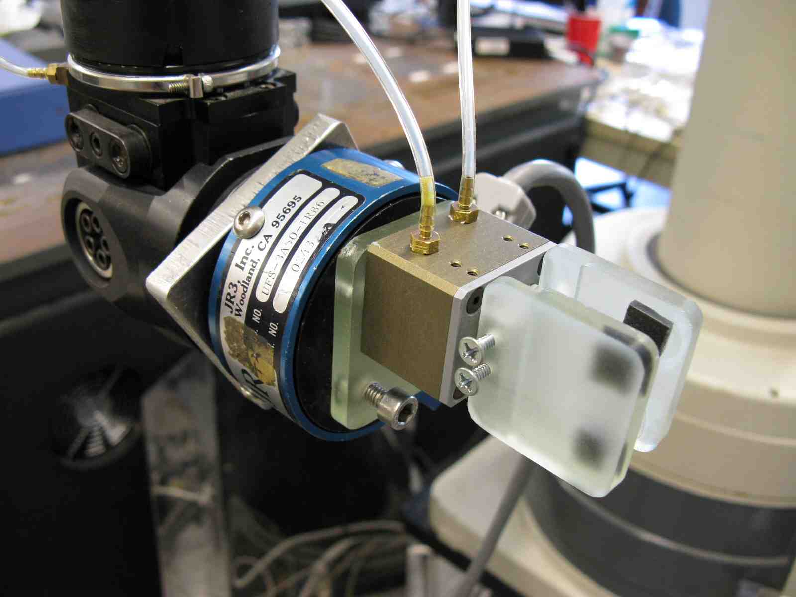
- Finished machining the extension for the Adept gripper and attached them to the gripper. Without anything additional, the spacing between the plates is too big to grab the foam core airplane. With some sorbothane or other addition, however, it will be easy to grab the plane and since we'll probably want something softer than the urethane to be grabbing the plane anyway, this is good.
- I tried to attach the gripper to the Adept but I'm not sure if there is a special piece that needs to be added between the gripper and the arm. I took off the attachment that was on there and the existing holes were not oriented correctly to attach the gripper. I assume there's some piece and I'll ask Alexis tomorrow.
- I did hook up the modified gripper to the pneumatics system to see how well it works, and it's great. I also closed the gripper on a piece of scrap foam core to see how well it would hold; it held very tightly because of how stiff the sorbothane is. The downside of this is that without any changes the sorbothane will stick to the plane to some extent. When I opened the gripper, the piece of foam core remained stuck to two of the pieces of sorbothane, which would be a problem for throwing the plane.
- Repaired the plane after our last trial. I added some new toes to one of the foot (which had 3 of its toes break) and glued on the foot that popped off. The toes I put on are the next generation (after the ones that were already on there, so it will be interesting to see how well they perform. It will also be nice because we have one version on one foot and the other version on the other foot, so we can observe the performance side by side.
- Added to the Adept information in AdeptForPerching. Now everything I know about using the Adept is up there!
Tuesday, August 5th
- Designed a piece to connect the gripper to the wrist piece in Solidworks. It's just a simple square piece with holes to connect to the gripper and another set of holes to connect to the wrist. I cut the pieces on the HAAS and poured the Task 9 so the will be ready to use in the morning so hopefully we can start testing the suspension systems tomorrow.
- Continued studying the videos of the most recent suspension tests. I found some things to think about:
- It may be good to install a wire extension off the tail extending toward the wall. This will keep the plane pitched forward enough to engage the feet more frequently. In some of the clips when the plane hit the wall at a backward angle the feet couldn't engage properly. With the extension off the tail, however, I think they will engage much more easily. The wire we have on the first dummy plane was actually a good design, one that would be perfect for our current design. This is because it was sort of springy so when it hits the wall it builds up and then briefly after it pushes off the bottom which pitches the top forward (in theory) and engages the spines even better.
- Installing more vertical suspension will also most likely increase the likelihood of foot engagement. In a couple clips the feet would engage, build up some potential energy in the spring, and then release, launching the feet up enough so they disengage. With a suitable suspension system this effect should be eliminated.
- Having different toes in the feet may change the performance as well. As we've seen, the new toes weren't too great, but the next generation should be better.
- The plane performed the best when thrown at a higher arc so it had less horizontal velocity and a little negative vertical (downward) velocity. This way the feet would engage and would not bounce off horizontally. We threw it more horizontally and it bounced off for these two reasons (no engagement and too much recoil). This can be taken care of in the control scheme (or I suppose we could alternately try to design a system that works equally well regardless of the trajectory, but that's sort of a long shot.
Wednesday, August 6th
- Spent the day working with the Adept.
- This morning I attached the gripper to the arm using the extra connector piece I designed yesterday. Everything fit perfectly so it was a good start!
- Having the gripper actually on the arm allowed me to observe when in its trajectory the gripper would actually release. I made a simple straight line path for the arm to follow and successfully threw a weighted piece of foam core board. At first I kept it at 80% of the operating speed, and eventually bumped it up to 125%, which was extremely fast! At different speeds, the distance the arm travels on its first path (to gain speed) and its second path (to throw the plane) change, or at least the ratio of the two. For example, at higher speeds we need the second distance to be greater so the speed can be attained by the time it is released. In fact, it's still a little hazy to me exactly when the gripper releases in the current scheme. I'm going to examine this more closely tomorrow.
- Toward the end of the day I had a great trajectory working and managed to throw the weighted foam core all the way to the file cabinets (sorry Aaron!). Tomorrow we'll attach the plane and see how well it works. We'll have to increase the speed for sure to counteract the weight and increased air resistance from the wings.
- Tomorrow I'll also start trying to make a program that oscillates the arm sinusoidally up and down to test the suspension systems.
Thursday, August 7th
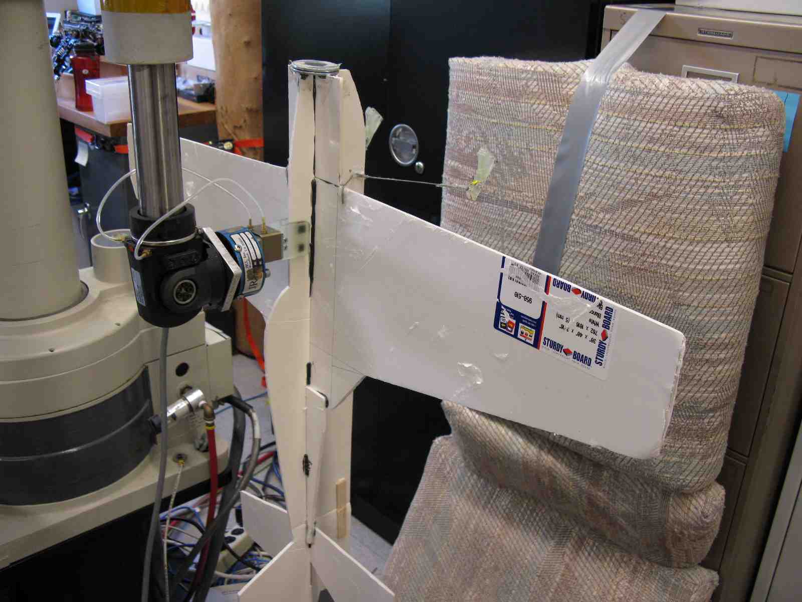
- Continued working with the Adept, trying to find the best way to throw the plane. We actually threw the plane with the arm today and it was pretty awesome! Because we don't have an appropriate "wall" made yet, we duct-taped a couch cushion to the file cabinet and the plane stuck to it every time (as expected since the spines can easily penetrate the fabric).
- We started with diagonal arm trajectories and they worked rather well, but such runs were restricted because we only have 150mm of vertical range with the arm. As a result, we couldn't get much initial vertical velocity; in fact, it seemed that there was almost none because of the weight of the plane.
- Since we couldn't really create significant vertical velocity, we decided to try completely horizontal paths. This worked to some extent but it was still difficult to accurately determine the release point (when the gripper lets go of the plane).
- The next step is to figure out what sort of tests we want to run and how we want to make the measurements. It's difficult to measure exactly how far the plane falls or when the gripper releases, so those are some of the challenges.
- I didn't get to the sinusoidal program today, so maybe tomorrow!
- A view of the Adept gripper. The custom urethane parts are visible as well as the sorbothane we added for grip:
- Here the gripper holds the plane in the ready position before it throws it against the cushion:
Friday, August 8th
- Worked with the Adept a little more, but started thinking about potential alternatives. Since the vertical range is quite small and the vertical velocity is slow, Alexis and I think we might want to seek other methods of testing. One thing we might do is consider pneumatic cylinders as a means of launching the plane. If we got one that was large enough, it could actually work quite well. John suggested this idea, as well as pointing out that as long as we rig up some sort of speed-measuring system it's not as important to have a mechanism throwing it whose velocity we can control. We don't really need to have the same initial speed each time; as long as we know what it is though, we can still achieve our goal of knowing the trajectory.
Week of August 11th
Monday, August 11th
- Looked online for pneumatic cylinders for a while but then realized I didn't really know what to look for. Since we're not sure exactly how we're going to move forward with the "throwing the plane" experiments, I figured I might as well wait on it.
- Began investigating how the suspension systems perform under sinusoidal forcing. I started with some simple math (coming up with the equation F = -kx - bv - f*sign(v), where k is the spring constant, b is the damping constant, and f is the frictional force). Then I plotted this function in MATLAB and came up with some interesting plots. I didn't get to entering the parameters for our exact experiment so the plots don't relate to our situation yet. Tomorrow I'll make the more appropriate plots and post them up here!
Tuesday, August 12th
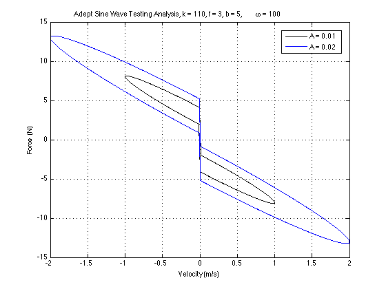
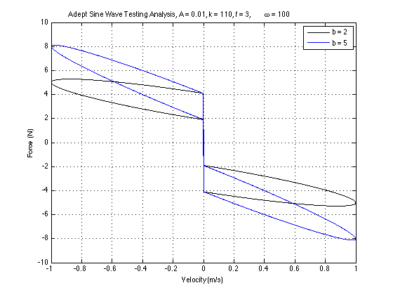
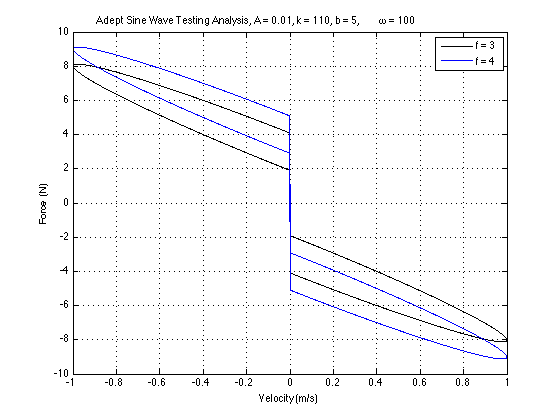
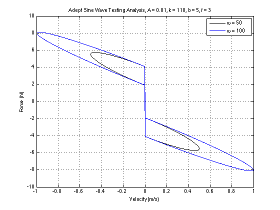
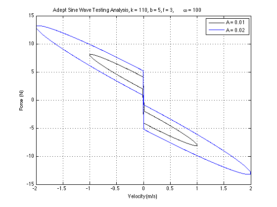
- Continued playing with the MATLAB plots of the suspension modeling. We want to see how changing each parameter changes the force vs. velocity plot (see example plot below). This way, we can optimize the system to achieve conditions like the ones in the model.
- An example of the suspension with a sinusoidal forcing function.:
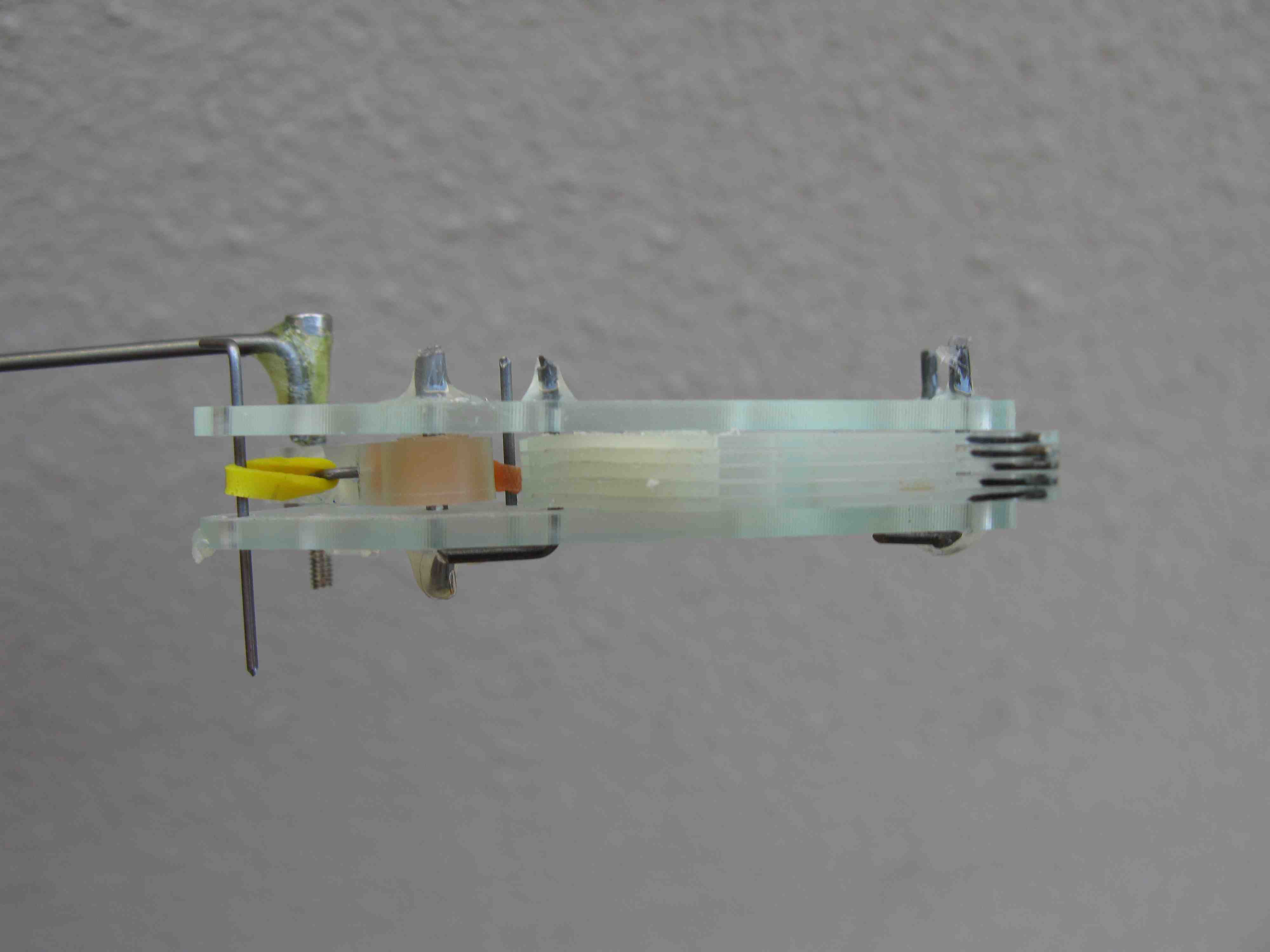
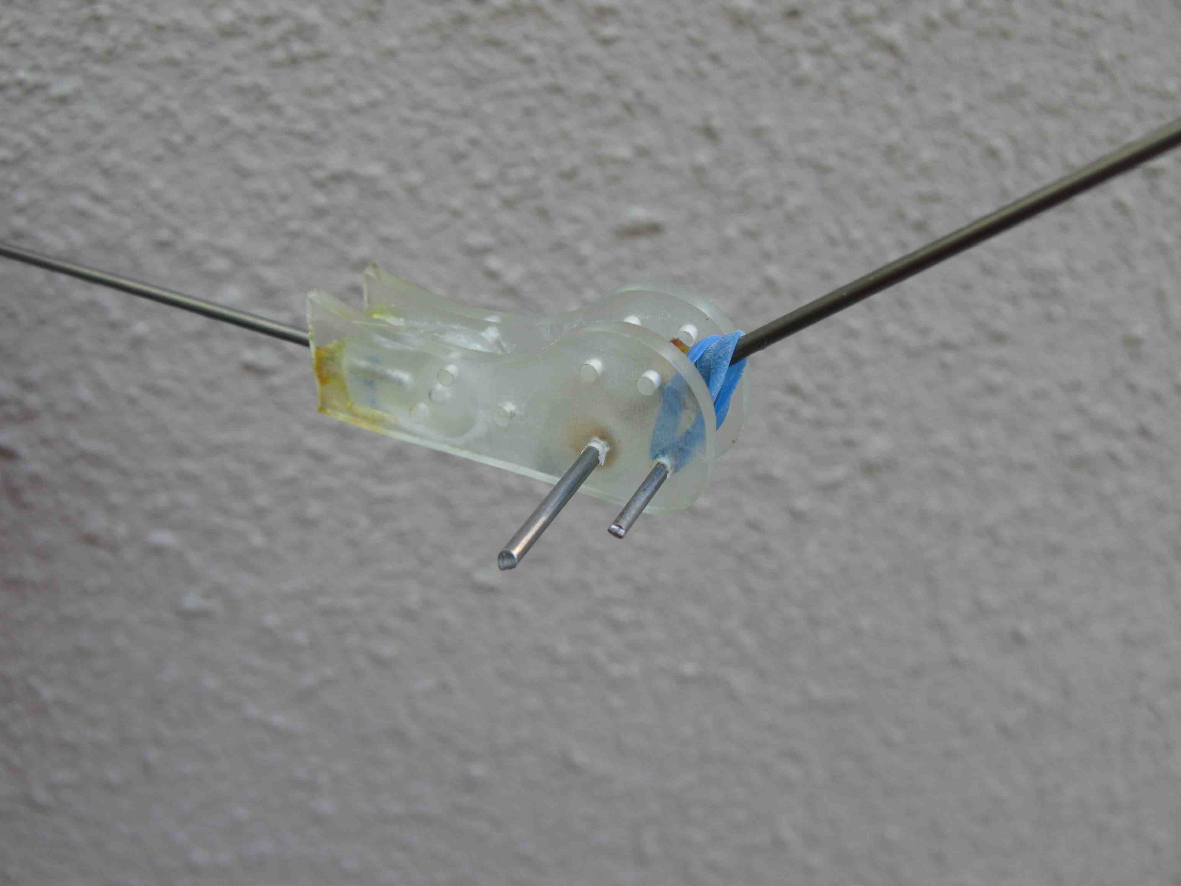
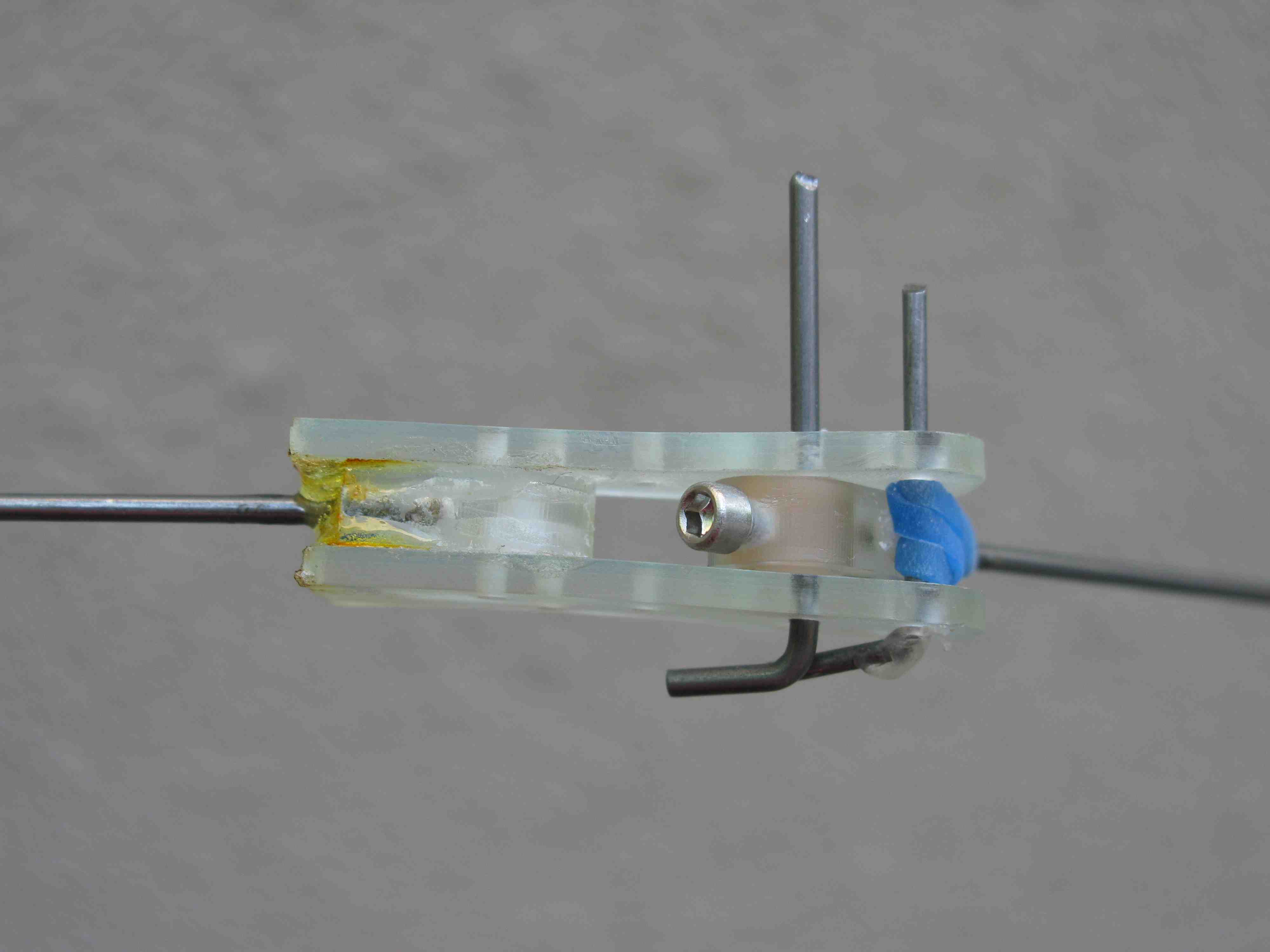
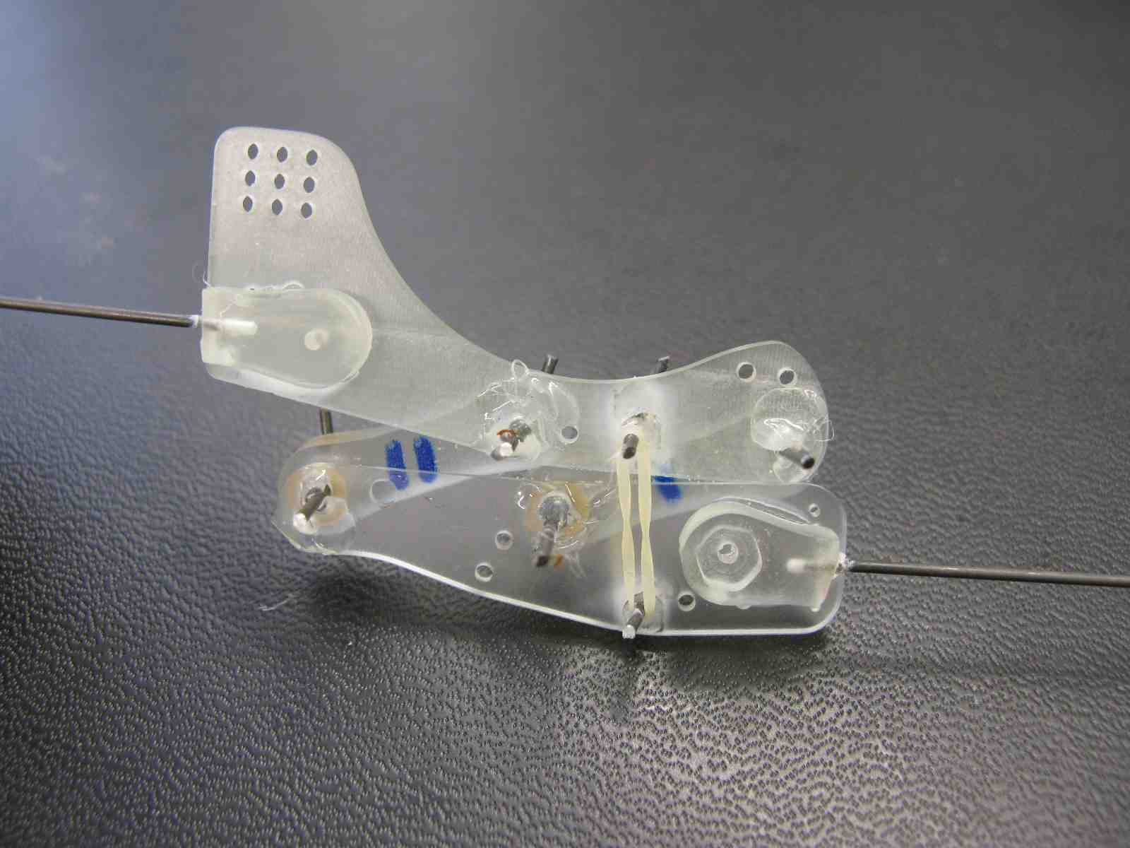
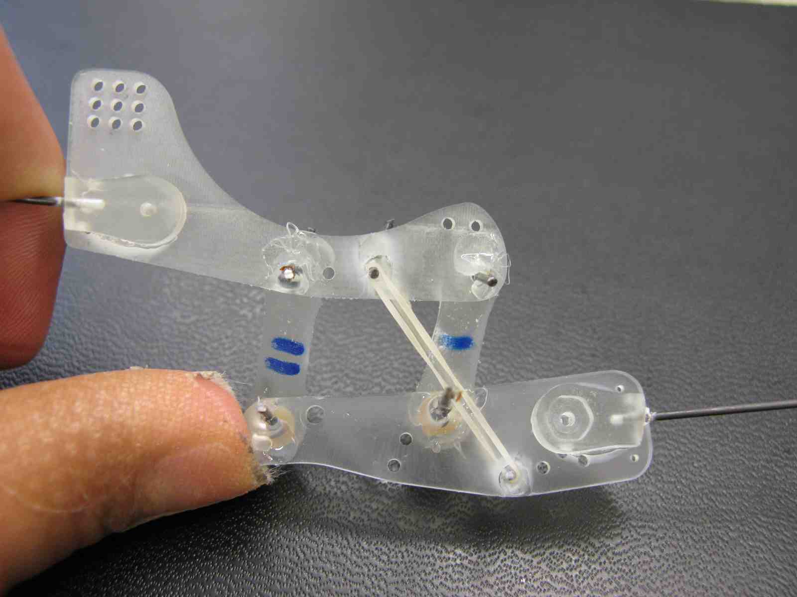
- Made a prototype of a vertical suspension system for the legs (see images below). It could be used in addition to the current horizontal suspension or in place of it; the latter may require a better horizontal compliance in the new suspension. This new design is good because it allows for extension using rotation, and if we use the friction damping idea from the newest ankles we might not need additional damping. Right now the prototype is larger than it would be if we chose to make one for the plane but it gives us an idea of the movement we'd be dealing with.
- The new vertical suspension design. (Fully compressed):
- A half-extended view of the new design.:
Wednesday, August 13th
- Studied the MATLAB plots of the suspension further. I ran through each parameter and on each graph plotted two curves, each with a different value of the parameter. See images below, along with explanations of how each parameter changes the system performance.
- Varying k causes the plot to "squeeze together", making the curves closer together, where a greater k results in a wider curve:
- Varying b results in a change in the "angle" of the graph, where a greater b means a steeper graph:
- Varying f shifts the curves up and down, basically changing the height of the graph, where a greater f causes a larger height differential between the curves:
- Varying omega (angular frequency of oscillation) alters the length of the curved parts of the graph, where a greater omega results in a more extended curve:
- Varying A (amplitude of oscillation) changes the length of the curved parts of the graph as well as "squeezing" the top and bottom of each curve closer to one another, where a greater A means a wider and longer curve:
- Started thinking of ideas for how to add more horizontal compliance into the new leg suspension design. The first thing that came to mind was to make the middle section of one of the struts going from "thigh" to "shin" on the leg (what we previously used as ankle pieces) into a soft part to allow some extension and bending. This way, when the foot is pushed backward, this "knee" design will allow for some travel and since it's just a piece of thick soft plastic bending, there's considerable damping. I'll continue to think of other possible horizontal suspension ideas tomorrow, even though both Alexis and I think the new design is probably pretty good even without added horizontal compliance.
Thursday, August 14th
- Began working with the Adept to figure out how to create a sinusoidal oscillatory motion to test the suspension. At first I roughly estimated the necessary increments for the arm to make to mimic a sine wave. I told it to go 1mm, then 2, then 3, then 4, then 4, then 3, then 2, then 1, etc for as many iterations as we need. This is rather rough however, and does a poor job of actually modeling a sine wave. Additionally, because of how the Adept executes motion commands, I think all these movements were actually blended together into essentially a single motion up and down. To circumvent this issue, we discovered the ALTER command which is used to change a path already in progress. In our situation it is useful because ALTER makes the robot execute the commanded movement in a 16ms time span. If we know how long it takes to move to a given point, we can essentially determine its speed during each movement knowing the distance commanded as well.
- I did a simple sine wave analysis to determine how much the height of the curve decreases for each incremental change in x. I used pi/8 as my dx increment, which allows for relatively good precision while keeping the necessary coding reasonable. I didn't get to putting these numbers into the Adept so I'll do that tomorrow!
Friday, August 15th
- Read through the paper that Mark and Alexis started and gave my input on it.
- Started drawing up ideas for the realization of the leg suspension prototype. There are several factors to consider in the design of the real part, and even though we can change the design later on I'd still like to try to optimize it now.
- We can either make the pieces that attach to the leg (leg pieces) or the struts that go between the upper and lower extensions the thicker pieces. As it is not (in the pictures above), the struts are the thick pieces, but that's not necessarily the best design. Weight isn't really a consideration due to the small size of the joint, so performance is the only really important thing to think about. It makes more sense to me to have the leg pieces be thick because we have to attach the leg rods to them anyway and this will be easier with a larger cross-section.
- Either way, we will integrate a soft part into the piece (where the pieces rotate about one another) to add damping. To control the amount of friction, we'll also put in one of two potential ideas: the first is what we have on the current "knee" - a small bolt that tightens or loosens the soft part against the rod; the second would involve cutting a hole in the middle of the urethane piece so it can be closed or opened using a nut and bolt. The first idea tightens the rod in a single direction, whereas the second idea increases the friction in all directions.
- We can either have the joint independent from the body of the plane itself (as it is now) or we can integrate it into the plane. Attaching it to the plane would eliminate one of the leg pieces, leaving the two struts and a single leg piece. This would most likely be stronger and it would keep the added mass closer to the center of mass of the plane. Since the mass is quite small, this effect isn't to important but still good to think about. The decision will come down to how much travel we want/need in the horizontal direction as well as a couple other considerations.
Week of August 18th
Monday, August 18th
- Sketched ideas for the new leg extension design before making them in Solidworks. At this point I plan to make some of the idea where the joint is away from the plane, and some of the idea where part of the joint is attached to the underside of the wing. When we get the HAAS back, I'll make them and hopefully they'll work as well as we think!
- Began thinking about and designing my poster for the end-of-summer SURI presentation. Alexis helped me get ideas of what to put on it. I think we're going to do an overview of each component of the project rather than going deep into a single system. I'll keep working on this and make it great!
Tuesday, August 19th
- Made all the new leg extension pieces in Solidworks and made the wax block assembly. Now, once we get Unigraphics working and we have the HAAS, we can make the new extensions. We're making 4 different pieces: 1) a two-holed piece that can attach to the underside of a wing; 2) a leg piece with holes for soft parts for added friction when rotating; 3) struts to connect leg piece to leg piece or wing piece to leg piece; and 4) struts with a soft part in the middle to add compliance. As soon as the HAAS is up and running we'll get an idea of how well these will work.
- Continued working on my poster for the SURI presentation. Since there aren't any posters about the perching project at all yet, I want to make it nice so it can explain the project.
- Pete showed us the program he made to measure forces on the Adept. We can input any function and then generate MATLAB plots of our data. Tomorrow I'm going to add to the AdeptForPerching page to incorporate instructions on how to do this.
Wednesday, August 20th
- Fixed one of the designs in Solidworks (realized the drill bit was too large to fit through one of the paths).
- Talked with Alexis about what to put on the poster.
- Started working with the Adept and force sensor program that Pete showed us yesterday. I added the necessary information to the AdeptForPerching page, so we should be able to run the programs on the other computer reading straight from that page. I went through the steps Pete showed us yesterday, and they all went smoothly and easily. I ran the program he set up and successfully created some MATLAB plots of the force on the wrist of the Adept. Tomorrow, I'll attach the gripper to the Adept and try to get some readings using the actual plane and a reasonable sine function.
Thursday, August 21st
- Continued the poster. At this time I have sections for Overview, Foot Design, Suspension Performance Analysis (containing MATLAB plots from our mathematical analysis and the Adept testing), Throttle vs. Drag Analysis, and Equipment, as well as a centered picture of the whole plane. The poster looks really good so far; I'll post the first draft on here when it's done.
- Began using the Adept for sinusoidal suspension analysis and obtained a plot or two. Unfortunately I hit some bumps in learning the transition from the direct Adept computer and the other one so that took some time, but I managed to figure it all out and by the end of the day I had plots of exactly what we want. Tomorrow I'll do some more testing and hopefully get some plots that resemble the ones we got mathematically before!
Friday, August 22nd
- Came close to a finished first draft of the poster. I only need to add material for the Control System Design section (which will come from Alexis, since I wasn't too involved in any of that), a schematic of the plane's approach to the wall with commentary, and a good picture of the plane either hovering or perched on the wall. I'll definitely be done with the first draft by Monday (I have to have it finished by Wednesday so I can get it to Kinko's).
- Built a second "prototype" of the new leg extension design. We want to get some testing done with this design and since the HAAS has been unavailable we figured we might as well make one more out of scraps. I also made two more feet, so we can make the complete legs and attach them to a plane and test it. Tomorrow we'll give that a shot and hopefully get some good results!
Saturday, August 23rd
- Worked with the Adept a little to find out how accurate the plots would be and if they would in any way match the plots we made mathematically in MATLAB. It was difficult to gauge how successful the trials were; there are a lot of places where differences or errors could be introduced. We calculated the values of the parameters (k, b, f) and they weren't exactly what we were expecting, both in terms of magnitude and in terms of sign (some were negative while others were positive). On Monday I'll continue trying to figure out how to interpret the results.
Week of August 25th
Monday, August 25th
- Conducted suspension testing with the Adept. We used the program Pete made for us and tested the first version of our suspension and the second version with the "knee" joint. We got some good plots, showing increased damping in the second version of the suspension as well as comparing the model to the actual forces, and they were very similar. The results varied depending on where we set the zero displacement position to be (i.e. how much the legs were compressed in the zero position). A large factor also was whether or not the toes were at their overload protection (no more travel). See plot below:
- Comparison of Suspension Performance:
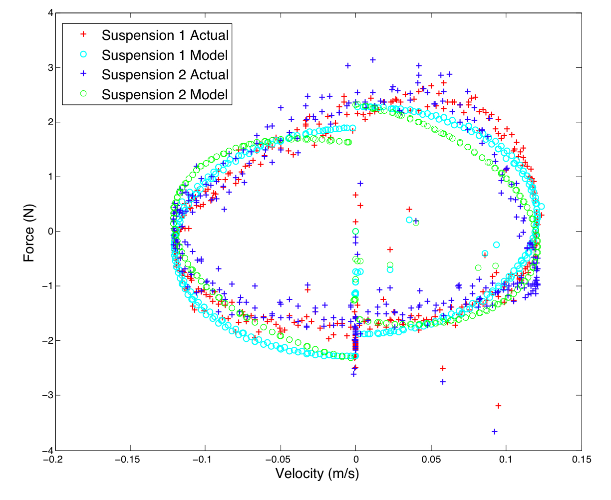
- High resolution version: AdeptSuspensionTesting.pdf:
- See also new page about testing: AdeptSuspensionAnalysis
- Finished the first draft of the poster, complete with all necessary plots, circuit diagrams, equations, and schematics. Posted it on chewie for Mark and Alexis to look at and give feedback before we get it printed.
Tuesday, August 26th
- Finished the final draft of the poster. Alexis and Mark gave their feedback and it's ready to be printed. I plan to bring it in tomorrow morning so it's ready by Friday (or hopefully Thursday).
- Here's a low resolution version of it: SURIPoster
Ideas, requests, problems regarding TWiki? Send feedback