new web: http://bdml.stanford.edu/pmwiki
TWiki > Rise Web>ClimbingRobot > ForceSensingAnkle>SecondPrototype (30 Aug 2005, YongLaePark)
FSA Prototype 2 Fabrication and Test
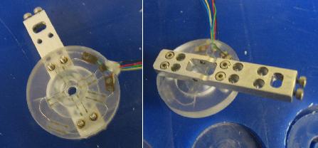
Physical dimensions of the second prototype is the same as those of the first prototype. The main differences are:- Semiconductor strain gages are embedded to the load cell instead of foil gages.
- Three axial forces can be measured at the same time.
- Figure 1: Prototyp 2
Fabrication
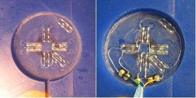
The second prototype was fabricated using SDM process. Figure 2 and 3 show the fabricaing process.- Figure 2: Strain Gage Placement and Wiring
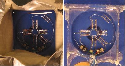
- Figure 3: Polyurethane Pouring and Curing
Calibration Test
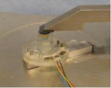
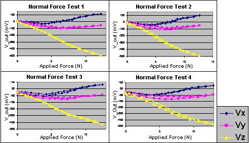
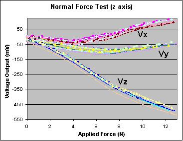
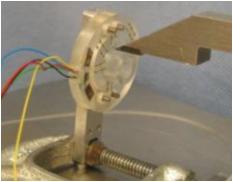
Force calibration tests were conducted in all three axial forces using a scale and a height gage. Four same tests were conducted for each aixal force test, and all are force loading-unloading tests to check the hysterisis too.Normal Force Test (z-axis)
- Figure 4: Test Setup
- Figure 5: Test Output Plots
- Figure 6: Combined Output Plot
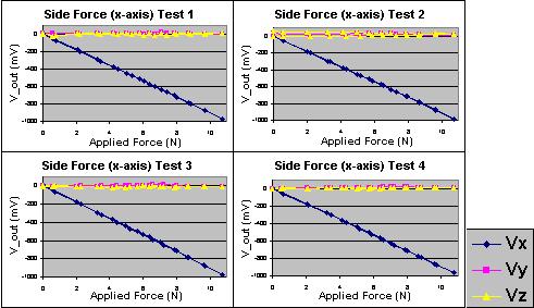
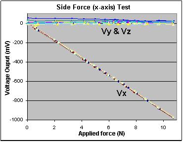
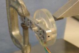
Side Force Test (x-axis)
- Figure 7: Test Setup
- Figure 8: Test Output Plots
- Figure 9: Combined Output Plot
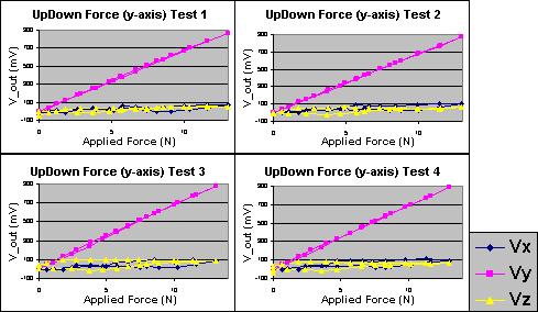
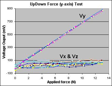
Up-down Force Test (y-axis)
- Figure 10: Test Setup
- Figure 11: Test Output Plots
- Figure 12: Combined Output Plot
Ideas, requests, problems regarding TWiki? Send feedback