new web: http://bdml.stanford.edu/pmwiki
TWiki > Rise Web>ClimbingRobot > RobotPlatform>PlatformConcepts (31 Jul 2010, DanAukes)
Platform Concepts
- This page contains information about the evolving platform design. -- AaroSaunders? - 29 Aug 2003
- Switched to reverse chron. order 11-14-03 MarkCutkosky
Platform design as of Nov. 14 Telecon presentation by AaroSaunders
 Powerpoint slides (password restricted access)
- Having fully servoed drive and sprawl angles is nice, but I wonder if servoing the sprawl angle will be necessary. Perhaps flexures are more appropriate here? Also, with 2 motors constantly running in order to run the crank, how energy efficient is this design when lightly loaded? Also, since the robot will nominally run with an alternating tri-pod gate is there a clever way to reduce the number of motors like SangbaeKim has done with IndependentSprawl? -- WillP? - 01 Sep 2003
Initial Foot Concept Sept. 2003 WillP
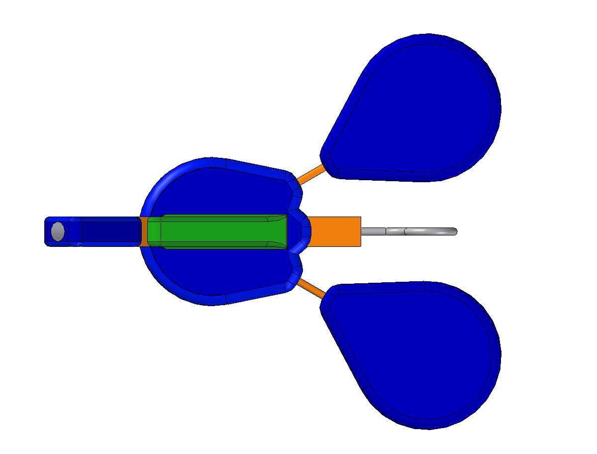
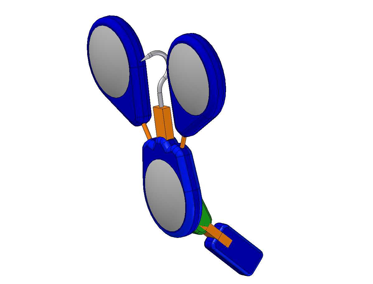
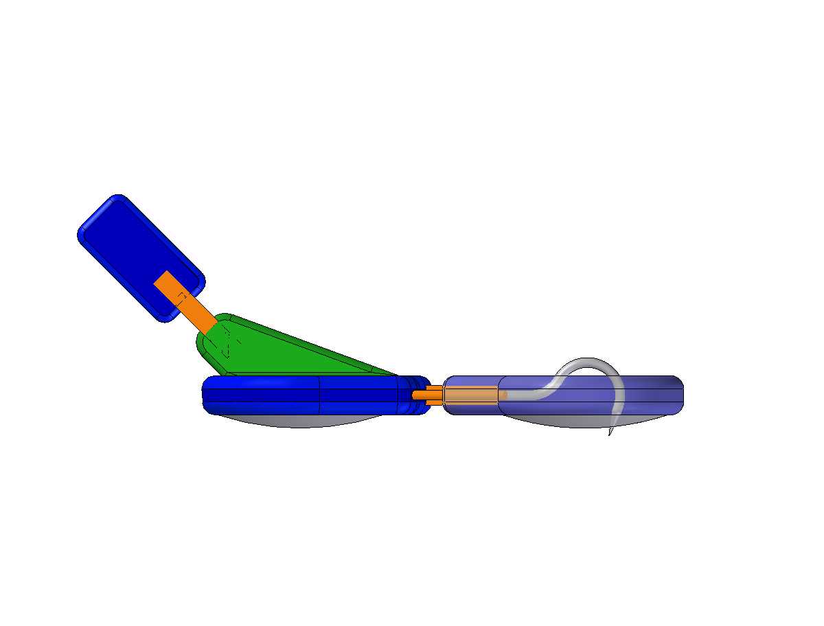
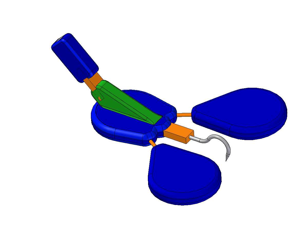
The initial concept for the robot feet is based on the fan-footed gecko. The design is completely passive and includes flexures to realize key DOFs. The design includes a single claw per foot and compliant foot pads that are intended to covered in synthetic dry adhesives (from Ron Fearing's group).Foot Design Details
Starting from the ankle and working towards the toes... The ankle incorporates a 1 DOF flexures to accomodate rotation in flexion/extension. The underside of the foot is covered with 3 foot pads (one on the base of the foot and one on each toe). These pads will consist of a thin gel-filled membrane and will be covered with dry adhesives. Each toe is joined to the base of the foot with simple spring-wire flexures, which give the toes both a flexion/extension DOF as well as a ad/abduction DOF. The flexion/extension DOF (of the toes and ankle) is important for both mating and peeling the feet off of surfaces. The ad/abduction DOF is important for aligning the toes with the direction of slip (gravity). The claw is embedded in a 1 DOF flexure. It is envisioned that the claw would skim over smooth surfaces and would only become the primary mode of "adhesion" when surface geometry provides interlocking features for it to engage. The foot incorporates compliance at 3 levels: ankle compliance, toe compliance, and foot pad compliance. Together these allow the foot to conform to irregular surfaces.- Foot concept pictures


 -- WillP? - 01 Sep 2003
-
 One thing that we'll have to work on is the compliance of the toes. Ideally, it should be possible to apply a respectable normal force at teach toe pad on first contact (to help 'seat' the dry adhesive). Subsequently, it should be possible to load the entire foot almost entirely in pure shear, with perhaps a bit of tension distributed uniformly over the foot to maximize the benefit of adhesion. There should be no bending moments applied through the foot until we are ready to unpeel it. This may require semi-active 'selectively compliant' toes. MarkCutkosky 9-1-03
Flexa-RHex [Concept A]
Based on the idea that perhaps the legs do not need to spread independently, a modifed version, dubbed "Flex-a-RHex" was created. Essentially, this robot is similar to RHex with 4-bar mechanisms instead of rotary legs (for longer ground contact) and with a single active folding axis that can be bent upwards for a more sprawled posture, or downward for hugging a cylindrical object such as a tree trunk. In addition to the one active folding DOF in the body, there are 4 passive bending DOF provided by compliant flexures, presumably made by ManufacturingHome. These are intended to facilitate horizontal/vertical transitions.- large image in 3/4 view
- large image in side view -- the flexures are shown in orange.
- Zipped archive of solids models in various formats
First rocker-crank concept posted 8-22-03, WillP and SangbaeKim
Based on the 4-bar mechanisms on the LegPlatformDevelopment page, an initial rocker-crank mechanism was posted in Docushare in preparation for the 8-28-03 Kickoff meeting. Each 4-bar mechanism can tilt about a horizontal axis for a total of 12 DOF. The tilt axes are likely to have lower power requirements than the 4-bar mechanisms.Ideas, requests, problems regarding TWiki? Send feedback