new web: http://bdml.stanford.edu/pmwiki
TWiki > Rise Web>TWikiUsers > VirgilioMattoli > SensorFabrication>GaugeExperimentalSetup (09 Aug 2004, VirgilioMattoli? )
-- VirgilioMattoli? - 03 Aug 2004
 Picture of Experimental Setup
 Scheme of Experimental Setup
 Displacement and Force trasduction modules
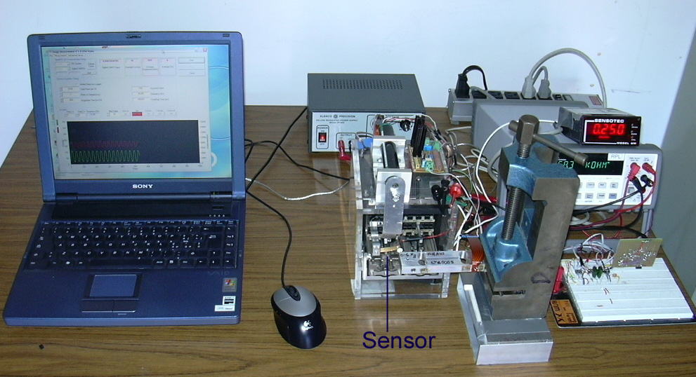
Experimental Setup for Embedded Gauge Sensor Tests
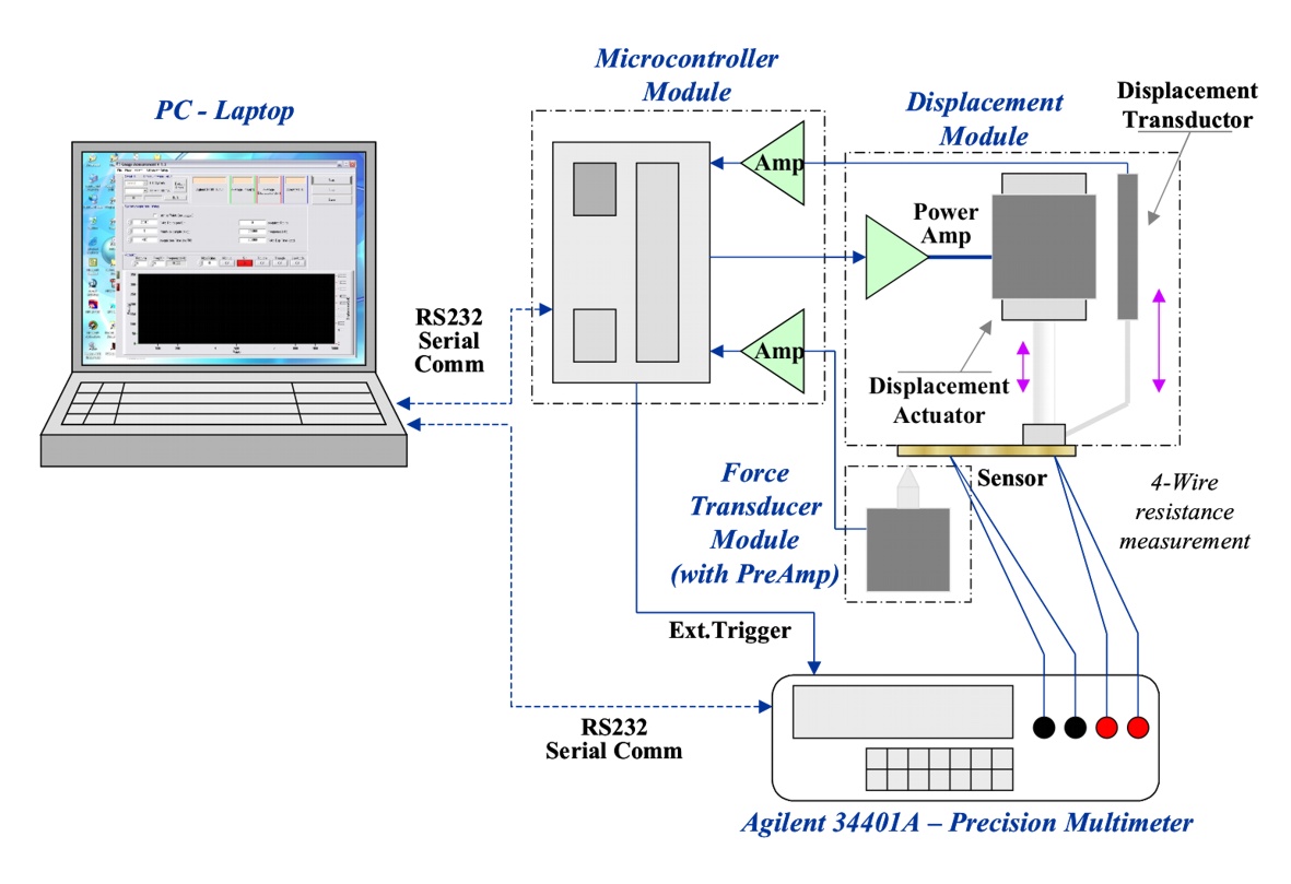
The experimental setup was designed for accurate measurement of resistance of sensor samples, vs. induced deformation. In order to generate strain in reproducible way a displacement unit was provided (actuator + sensors). Also force applied by the displacement unit was monitored. In the figure an overview (picture + scheme) of the whole system is shown. The system is composed by a Microcontroller Module, a Linear Displacement Module, a Force Transducer Module and a Agilent 34401A Precision Multimeter. The system is connected with a PC by two rs232 serial connection.
Picture of Experimental Setup
Scheme of Experimental Setup
Microcontroller Module
A microcontroller module is devoted to the control of other modules and also to interface the system with a PC by one of two serial connection. The microcontroller used is a PIC18F252? . The main functions of microcontroller module are:- conditioning and acquisition of analog signal coming fro other module (Displacement and Force transducers)
- generating signal and sequence for Linear Actuator Module (PWM signal)
- generate trigger for synchronisation of the multimeter acquisition
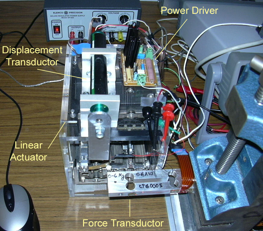
Displacement Module
The displacement module was obtained by an old hard disk of a main frame. The mechanism is actuated by a current generator: the force obtained change very linear with the current. The power driver provided for the current control is driven by a PWM signal. In order to minimise the electric noise on the system, this module is powered separately and the PWM signal (provided by the microcontroller module) is collected through an optoisolator stage. A linear potentiometer provided the right feedback of the position to the microcontroller module. Details are in ExperimentalSetupSchemes.ppt.Force Transducer Module
The force transducer was obtained by an old strain gauge based scale. The strain gauge bridge is preamplified by a Signal Conditioner/Indicators model GM by Sensortech (Lettorecelladicarico.pdf:). The preamplified signal is more amplified, filtered and acquired by the microcontroller module. Details are in ExperimentalSetupSchemes.ppt.
Displacement and Force trasduction modules
Agilent 34401A Precision Multimeter ( http://we.home.agilent.com )
This instrument is used for measuring very accurately the resistance of the sensor samples. For the resistance measurement is used the 4-wire configuration in order to eliminate the wire contribution to the measure. The instrument is directly connected by a RS232 serial connection to the PC, but it is triggered by the microcontroller module.PC and software
The whale system is connected with a PC provided with a specific developed software for the management of the system. Using this software is possible:- Acquisition of data from 3 analog channel (up to 1000 Hz @ 10 bit of resolution)
- Coefficients calibration for analog channels
- Configuration and Acquisition data from the Agilent 34401A Precision Multimeter (up to 25 Hz)
- Real time graphic of the measurement
- Save data in text file, suitable for analysis with other software
- Other Stuff
Ideas, requests, problems regarding TWiki? Send feedback