new web: http://bdml.stanford.edu/pmwiki
TWiki > Rise Web>TWikiUsers > LaurelFullerton>FeetForStickyBotII (28 Aug 2008, LaurelFullerton)
Feet for StickyBot II
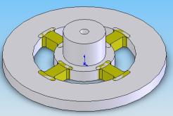
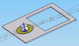
Currently, StickyBot II does not climb as well as the original StickyBot. Also, neither robot has managed to climb using microwedges. New feet are being designed in order to improve the climbing ability of StickyBot II using DPS stalks, or microwedges with electrostatic adhesion. New feet are being designed for StickyBot II. These feet feature ball joint-like structures to allow the adhesive on the foot to align with the climbing surface. Ideally, these feet will work with microwedges as well as DPS stalks.Version 1 Foot Design
Preliminary Results
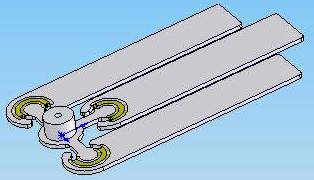
The first problem with the Version 1 feet was that the back corner of the footpad hit the robots leg. This problem was alleviated by removing the bottom corners of the feet with a Dremmel tool. It was also noticed that stalks further away from the ball joint did not engage nearly as well as stalks near the ball joint. Stalks at the ball joint would be pressed completely flat while stalks at the top of the foot would not even be in contact with the wall. Because of this, adhesive patches are currently centered on the ball joint of the ankle.Version 2 Foot Design
Version 3 Feet Designs
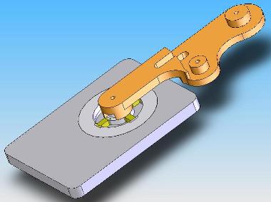
After much modification of the Version 1 design it was found that in order for the robot to stick, the adhesive patch needs to be located further from the ball joint. Also, the Vytaflex in the ball joints of the version 1 feet ripped out. Because of this, new designs have been drawn up. These designs are much thinner and longer than the original feet and have solid Vytaflex flexures rather than four thin flexures. Thin spurs will be made to attach to the bottom of the foot below the ball joint. This will help the patch come into contact with the wall.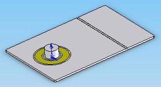
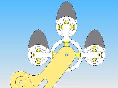
-- LaurelFullerton - 20 Aug 2008 Prototypes of all three versions of the foot were built but the first batch was unsuccessful. The fabric embedded in the ball joint did not bond with the vytaflex at all. A second batch has been started, this one will not have any fabric in the flexures.
-- LaurelFullerton - 28 Aug 2008
Future Work
Once the second batch of feet cure I will mount DPS stalks and microwedges on them and try to make StickyBot climb. The frame feet will have electrostatics while the other designs will use normal adhesives.-- LaurelFullerton - 28 Aug 2008
Ideas, requests, problems regarding TWiki? Send feedback