new web: http://bdml.stanford.edu/pmwiki
TWiki > Main Web>MobileManipulation > SquareOne>SquareOneStripSensors (29 Oct 2010, BarrettHeyneman)
Square One Strip Sensors
Overview
In order to give Square One a set of sensors that they could quickly work with and begin gathering tactile data, we built a set of 4 sensors, each with 3 taxels, for use on a parallel jaw gripper. The active pads of the sensors are ~1cmx1cm and arrayed in a line. The sensors are sampled by an AD7147 capacitance-to-digital conversion chip which communicates to a PC via PIC microcontroller and an FTDI USB->Serial chip.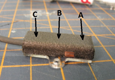
Construction
The sensors needed to be constructed quickly, so we used boards already on hand. We took a single 12 taxel board originally created for evaluating the AD7147 and cut it into 4 pieces. These boards had a shielded 4-conductor cable soldered to them. An acrylic spacer and backing were glued to them, then they were covered in double-sided foam tape and a conductive fabric. Construction details follow. 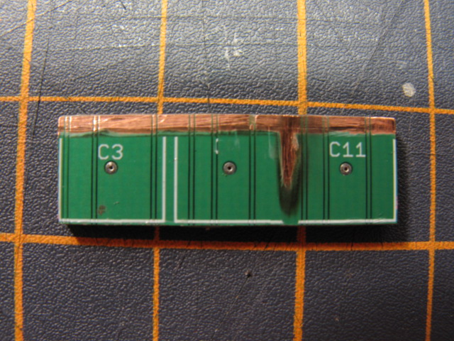 |
Each board is prepped by removing the solder mask layer on the back side to expose copper for the active shield. |
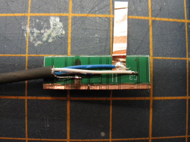 |
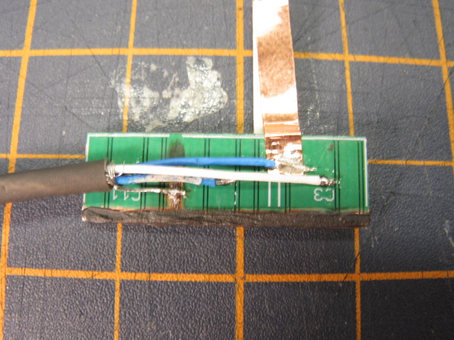
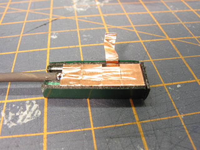
The cable shield is soldered to the exposed copper. Three of the wires are soldered to vias in the active pads, while the fourth is soldered to a piece of conductive copper tape. This tape is later used to make a ground connection to the outer layer of conductive fabric. |
|
|
More conductive copper tape is wrapped around the acrylic spacer. This tape completes the active shielding around the area where the cable shield was removed to make connections. The spacer protects the cable and the solder connections to the board. Notice the gap in the copper left on one side of the spacer. This is where the copper tape for the ground connection runs. |
|
|
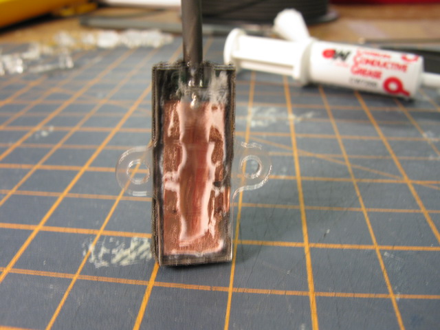
Conductive grease is applied to the exposed copper on the board. When the spacer is assembled and glued to the back side of the board, the grease forms the electrical connection between the active shield on the board and the active shield wrapped around the spacer. |
|
|
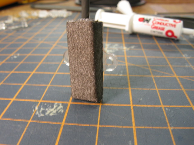
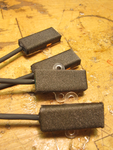
A layer of foam tape is then wrapped around the active side of the board and the sides of the spacer. This tape is not ideal for a dielectric layer as it exhibits slight hysteresis/creep. However, the ease of construction by not having to glue silicone foam to both the board and the Lycra layer is a worthwhile tradeoff. |
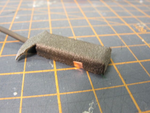 |
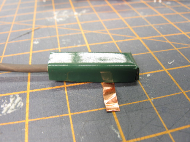
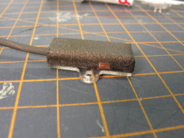
The outer Lycra ground layer is attached to the other side of the tape. The copper tape is routed along the side of the space and makes a connection to the Lycra away from the active area of the sensor. |
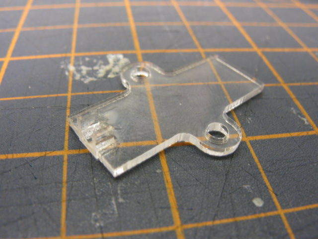 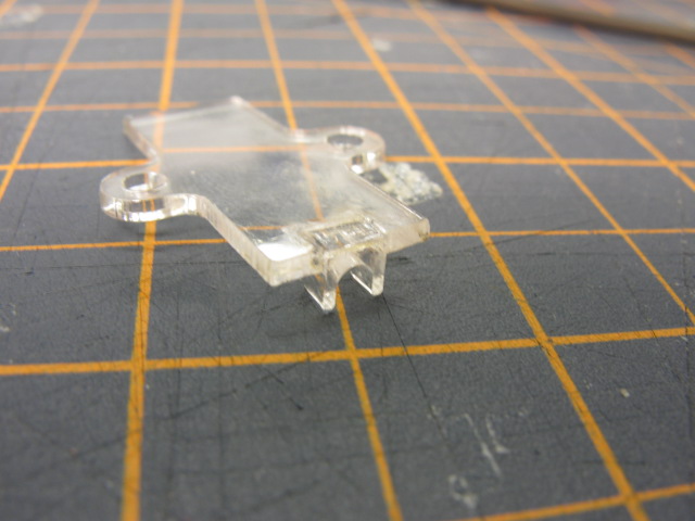 |
The acrylic cap is assembled. It contains a small end cap which clamps down on the cable insulation to provide strain relief. The back cap is slightly larger than the acrylic spacer to protect the edges of the foam/Lycra and prevent peeling. It contains two M2.5 clearance holes for easy mounting. |
|
|
The cap is glued to the spacer, and the edges of the Lycra are glued down to further prevent peeling |
|
|
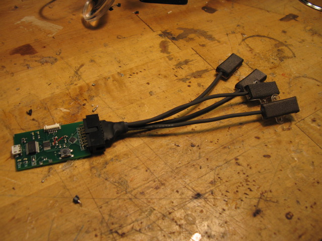
The four completed sensors are wired to a 16-pin connector so that they can be connected to the interface board. |
Electronics
The electronics are contained on a single board and includes three chips; an FT232R USB->Serial chip for communication with a PC, an AD7147 to sample the sensors, and a PIC microcontroller to communicate between the two and do very simple processing. Drivers for the FT232R chip can be downloaded here. Choose the VCP (virtual com port) drivers. You can then setup serial connections in Matlab (and other systems) to use the designated COM port.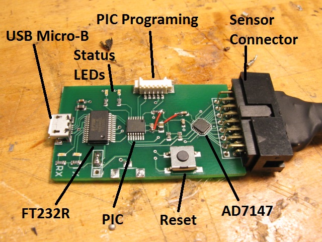 The interrogator board includes four LEDs for status indication. The two orange LEDs labeled TX and RX are controlled by the FT232R chip and indicate USB communication from the board's point of view. The red and green LEDs are controlled by the PIC and flash according to the following table to indicate the boards status.
| LED pattern | Status |
|---|---|
| Fast (~4Hz) alternating Red/Green blink | Initializing - PIC has just reset and has completed initialization of peripheral modules and the AD7147 |
| Slow (~1Hz) Green blink | Idle - System is running, but the PIC is not sampling from the AD7147 |
| Fast (~4Hz) Green blink | Streaming - the PIC is actively sampling from the AD7147 and sending streaming data packets to the PC |
| Fast (~4Hz) Green/Red blink | Calibrating - the PIC is actively sampling from the AD7147 and collecting statistical data, which will be sent to the PC when the blinking ends (~2-3 sec) |
| Slow (~1Hz) Red Blink | Error - There has been an error communicating with the AD7147 |
Communication
Communication between the PIC and PC is relatively simple There are two modes for data transmission from the board to the PC; the escaped mode allows for frame checking, while unescaped mode consists of raw data bytes. All commands and related data are outlined belowPC->Board
Communication from the PC to the interrogator board is simple; single byte commands are sent to change the operating mode of the board or to query the current mode. Response to the commands varies.| Byte | Command | Response |
|---|---|---|
| 0x08 | Escape - Send data bytes using the escaped data scheme (see Board->PC section) | None - data scheme changed |
| 0x80 | No Escape - Send data bytes unescaped | None - data scheme changed |
| 0x81 | Start Streaming - Begin streaming data from the sensors. | Continuous data packets |
| 0x82 | Stop Streaming - Return to the idle state, no more data sent from the board | None |
| 0x83 | Start Calibrating - Begins the calibration routine. Data is sent when the routine ends. | Calibration data after ~2sec |
| 0x84 | Stop Calibrating - Aborts the calibration routine prematurely. No data is sent. | None |
| 0x85 | Query Status - Board responds with the current operating mode. | Single byte indicating status |
Board->PC
The communication from the board to PC is more complicated. Data packets consist of a single command byte followed by an optional number of 2-byte data words (MSB first). The number of unescaped (see Escape Protocol) data words(bytes) is constant for each command. Upon power-up or a reset, the board sends a status byte, as if in response to a Query Status command (0x85). This allows any applications to verify that the board is running correctly before trying to use it. The commands and the associated data are outlined below.| Command Byte | Data W(B) | Description |
|---|---|---|
| 0x00 | 12(24) | Array of taxel readings: [1A, 1B, 1C ,2A.....4B, 4C] |
| 0x01 | 36(72) | Array of taxel data: [avg, min, max]. Individual data as above. |
| 0x02 | 0 | Status: Initializing |
| 0x03 | 0 | Status: Idle |
| 0x04 | 0 | Status: Streaming Data |
| 0x05 | 0 | Status: Calibrating |
| 0x06 | 0 | Status: Comm Error |
| 0x07 | 0 | Unknown command: returned when the PC sends a byte not in the previous table. |
| 0x08 | 0 | Escape byte (see Escape Protocol below) |
Escape Data Protocol
Optionally, the data from the interrogator board can be escaped; on reset the board defaults to unescaped data mode. In escaped data mode, any data byte (not command bytes) which has the same value as one of the command bytes in the previous table is preceded by the escape byte (0x08) and then inverted before being sent. See the example below.| Raw Data Bytes (sent in unescaped mode) | Escaped Data (sent in escaped mode) |
|---|---|
| 0x80 0x74 0x03 0xA2 0x1B 0x00 0x23 | 0x80 0x74 0x08 0xFC 0xA2 0x1B 0x08 0xFF 0x23 |
Ideas, requests, problems regarding TWiki? Send feedback