new web: http://bdml.stanford.edu/pmwiki
TWiki > Main Web>TWikiUsers > BenKallman>BenKallmanSummerBlog (05 Sep 2010, MarkCutkosky)
-- BenKallman - 16 Jun 2010
 dddddfdfdf
 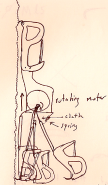 dddfdfdffd
 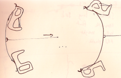 the upper toeddddddddddddddgrabber device similar to AVddddddd bi-stable spring. A small force will switch the orientation of the feet
There are a few questions:
the upper toeddddddddddddddgrabber device similar to AVddddddd bi-stable spring. A small force will switch the orientation of the feet
There are a few questions:
 , where
  , and
, and 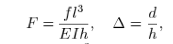 (Qiu, Lang, Slocum, 2004)
Where F1 is a nondimensionalized quantity including the force f in the diagram. Q and Delta are non dimensionalized using material attributes. In short, we have an expression for the smallest force required to dislodge a curved beam from one of its stable positions. The paper also discusses higher orders of buckling, which correspond to F2, F3, and so on. We, however, concern ourselves only with the minimum force required. Cool stuff.
I also started to work on the new Stickybot test rig that we will send to different groups that are working on adhesion technology. I'm going to redesign the foot a bit as per what John told me. Minor changes, but requires time to become familiarized with the part in Solidworks (increase familiarity in Solidworks as well!). Got SVN up and running. I learned a bit about how SSH works, TortoiseSVN? , secureCRT, etc. Monday I'll power through some of those parts, changing the foot design and starting on the test rig.I will keep the COM to glass vs. body length ratio the same so that anyone can stick the rig on a piece of glass and accurately predict whethet their pad will work with stickybot 3.
(Qiu, Lang, Slocum, 2004)
Where F1 is a nondimensionalized quantity including the force f in the diagram. Q and Delta are non dimensionalized using material attributes. In short, we have an expression for the smallest force required to dislodge a curved beam from one of its stable positions. The paper also discusses higher orders of buckling, which correspond to F2, F3, and so on. We, however, concern ourselves only with the minimum force required. Cool stuff.
I also started to work on the new Stickybot test rig that we will send to different groups that are working on adhesion technology. I'm going to redesign the foot a bit as per what John told me. Minor changes, but requires time to become familiarized with the part in Solidworks (increase familiarity in Solidworks as well!). Got SVN up and running. I learned a bit about how SSH works, TortoiseSVN? , secureCRT, etc. Monday I'll power through some of those parts, changing the foot design and starting on the test rig.I will keep the COM to glass vs. body length ratio the same so that anyone can stick the rig on a piece of glass and accurately predict whethet their pad will work with stickybot 3.
 This is a very rough estimate. This ignores gusts of wind that actually flow outward from the building (not likely to happen, but should be understood nonetheless). This also assumes relatively slow air on the ground. However, the figure - 25 Newtons - is a good place to start.
A fine day.
This is a very rough estimate. This ignores gusts of wind that actually flow outward from the building (not likely to happen, but should be understood nonetheless). This also assumes relatively slow air on the ground. However, the figure - 25 Newtons - is a good place to start.
A fine day.
 dddddddddddddddddddddddd
 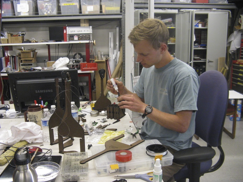 ddddddddddgoing into business dddddddddddddddddddddddddddddddddddddddddddddddd becoming a superglue wizard...
 note the linearity between shear force applied and normal force seen. Also note that the max normal force seen is around -7 N this is due to the weak vytaflex, which causes overload protection to kick in.
 A simple version of a gripper. The device has numerous problems and is just a first pass. It showed me that I need some way of keeping the spines in the vertical direction when not in use. I'll incorporate a torsion spring to keep the lever pulled all the way back. I still need to work out the problem of not enough travel up the wall in order to engage the spines. It's also really hard to describe these things in writing. Tomorrow I'll work on a second iteration.
And today was my first MERL fire drill!
A simple version of a gripper. The device has numerous problems and is just a first pass. It showed me that I need some way of keeping the spines in the vertical direction when not in use. I'll incorporate a torsion spring to keep the lever pulled all the way back. I still need to work out the problem of not enough travel up the wall in order to engage the spines. It's also really hard to describe these things in writing. Tomorrow I'll work on a second iteration.
And today was my first MERL fire drill!
 click image for animation
 dddddfdfdf
 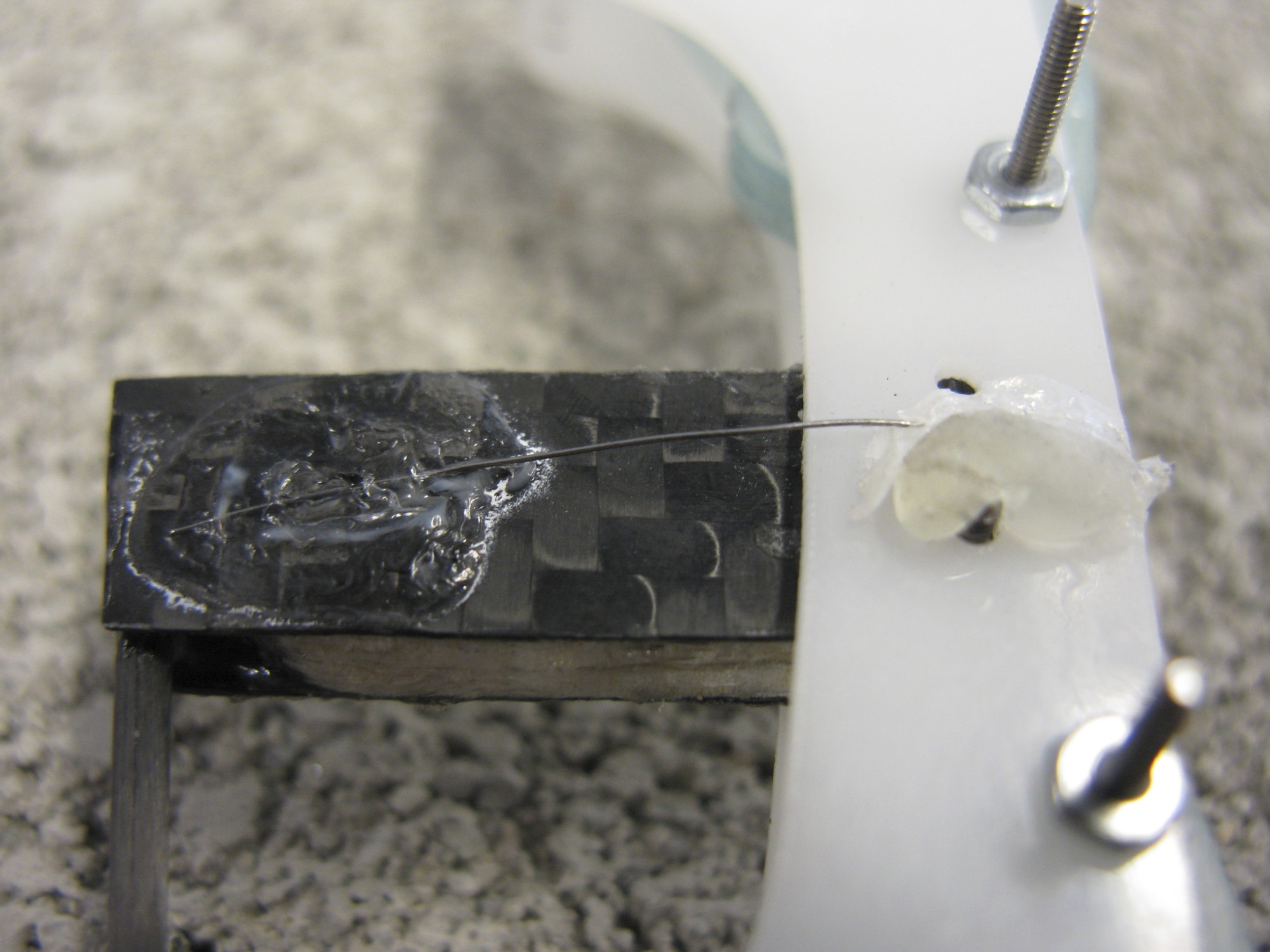 dddfdfdffd
 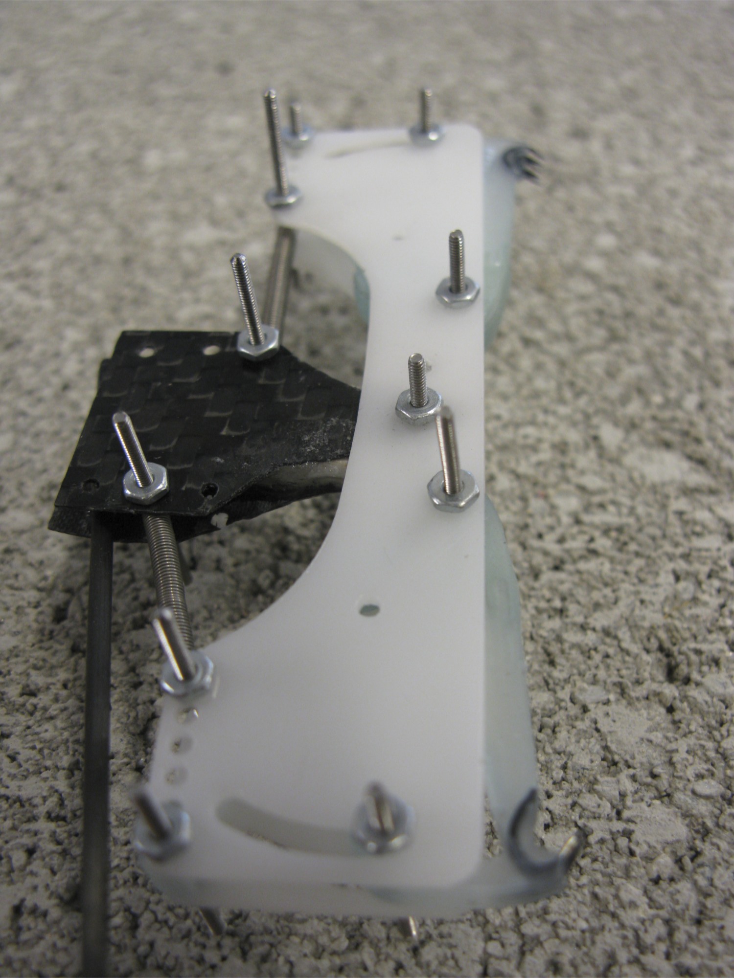 In the end, the simplest design works the best. A simple piece of spring steel glued between the plastic foot and the carbon fiber leg makes up the ankle... It is very compliant and seems impossible to beat in terms of weight. I'm thinking of better ways of attaching the wire, as glue seems slightly sketchy. Solder??
 I quickly realized that we need to know the diameter of the wheel before being able to go any further. This, of course hinges upon how hard we need to squeeze, which depends on how much adhesion we need.
Alexis ran by some ideas about how to find a better approximation for the forces that the plane needs to be able to withstand. We also talked about how it would be nice for the opposed spines to open upon impact and then close automatically. I will start to build a normally closed gripper with adjustable closing angles.
I quickly realized that we need to know the diameter of the wheel before being able to go any further. This, of course hinges upon how hard we need to squeeze, which depends on how much adhesion we need.
Alexis ran by some ideas about how to find a better approximation for the forces that the plane needs to be able to withstand. We also talked about how it would be nice for the opposed spines to open upon impact and then close automatically. I will start to build a normally closed gripper with adjustable closing angles.
 I think we are honing in a feasible design for the gripper. I built yet another normally closed gripper with NiTi? flexures. This version sticks fairly well without any internal squeezing force. I will refine this version and eventually mount it on the plane.
Alexis and I had a long discussion about goals. I want to have three things accomplished in the next three weeks:
* Prove that this opposed gripper design extends the landing envelope (avoiding rebounds)
* Get some data showing that the airplane can withstand wind gust forces
* Get a time-lapse sequence of the plane sitting on the wall of a building for a long (multiple day) period.
In order for this to happen I will do the following:
spruce up this current design. That means ensuring rotation within a plane, modifying the sideplates a bit, and modeling the flexure as two rigid bodies with a torsion spring connection. I need to pick a reasonable force with which to squeeze. This involves testing the validity of Alexis' limit surface graph. I also need to choose a method of actuation. I'm considering SMA springs, or a regular SMA wire with ratchet system.
I think we are honing in a feasible design for the gripper. I built yet another normally closed gripper with NiTi? flexures. This version sticks fairly well without any internal squeezing force. I will refine this version and eventually mount it on the plane.
Alexis and I had a long discussion about goals. I want to have three things accomplished in the next three weeks:
* Prove that this opposed gripper design extends the landing envelope (avoiding rebounds)
* Get some data showing that the airplane can withstand wind gust forces
* Get a time-lapse sequence of the plane sitting on the wall of a building for a long (multiple day) period.
In order for this to happen I will do the following:
spruce up this current design. That means ensuring rotation within a plane, modifying the sideplates a bit, and modeling the flexure as two rigid bodies with a torsion spring connection. I need to pick a reasonable force with which to squeeze. This involves testing the validity of Alexis' limit surface graph. I also need to choose a method of actuation. I'm considering SMA springs, or a regular SMA wire with ratchet system.
 I spent most of the day today (16th) building a new suspension system. The new fiberglass that I ordered is able to be cut on the laser, making for extremely strong and convenient pieces. I'm doing 1/16'' Balsa sandwiched between two .02'' pieces of fiberglass from ACP composites. If I had another month of summer I'd love to do some stress testing for this composite. It's incredible strong for it's weight.
In building new legs/hips, I've discovered that Tower Hobbies no longer carries the small version of the hinge that makes up the hip. I ordered some large ones and am currently redesigning the suspension to account for the large hinge.
I spent most of the day today (16th) building a new suspension system. The new fiberglass that I ordered is able to be cut on the laser, making for extremely strong and convenient pieces. I'm doing 1/16'' Balsa sandwiched between two .02'' pieces of fiberglass from ACP composites. If I had another month of summer I'd love to do some stress testing for this composite. It's incredible strong for it's weight.
In building new legs/hips, I've discovered that Tower Hobbies no longer carries the small version of the hinge that makes up the hip. I ordered some large ones and am currently redesigning the suspension to account for the large hinge.
Ben Kallman 2010 Summer Blog
June 16th
First day in the lab. I came in not knowing exactly what to expect and was quickly impressed by the welcoming atmosphere. Simply sitting down and listening to the conversation was inspiring. John made a point to go out of his way and teach Julia and I about surface mount soldering, show us his capacitive sensors, give a brief overview of Stickybot, and show us a microscopic resistor. I think being a fly on the wall in here will be fantastic. Anyway, on to what I learned: I spoke with Alexis regarding planes. After coming in to talk with him a few weeks ago I knew I was interested in the perching project. Today I finalized my decision and chose to focus my (initial) efforts on an opposed spine gripper for the plane feet. I think the first thing I need to do is make a list of the items that such a foot would ideally have, then I'll start to make some sketches and really rough prototypes. Alexis gave me some catch up reading (PerchingPapers). Some salient points:- woodpecker's toes are optimized for perching and have two long toes along the vertical axis, while climbing birds have toes that are more spread out and bent in the horizontal direction. This allows for greater vertical stability, but hinders lateral movement.
- paper discusses zygodactyl feet, meaning two sets of opposed toes. This might not be a bad design for airplane feet, assuming of course, one could manipulate them with a single motor. (update: actually this seems like overkill to me. Having strong, purely opposed toes will be plenty strong. We might as well go as simple as possible)
- in zygodactyl scansorial (climbing) feet, the toes spread apart and provide for more lateral stability.
- There is evidence that the orientation of the Zygodactyl feet changes depending on the task at hand. The Hairy Woodpecker will sit for hours and drill a hole for food, during which time the forward facing toes maintain a 15 degree separation angle. Once the bird starts climbing, the angle of separation increases to 25 degrees and one of the lower toes thrusts outward and sits at a right angle to the "fore toes."
- The horizontal toes act as pincers for lateral stability. This could be doable for airplane feet, would simply require a toe to swivel around into the horizontal position during perching.
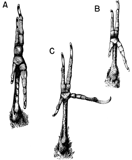
- Image at right: A. perching foot from the Pteroglossus genus B. perching and climbing foot from Celeus elegans C. climbing foot from Dryocopus pileatus (Bock, DeWitt? Miller 1959)
June 17th
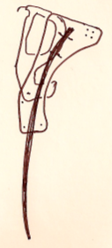
Ideas concerning releasable toes: Before I delve deeper into a design for a foot that can release and climb I need to test the current release mechanism, since Alexis said it wasn't perfect. I would, however, hate to redesign something that already works. Anyway, I'm currently thinking about the following: Two opposed toes, before landing the back toe will sit behind the front toe (toward the body of the plane). The front toe will make contact with the wall first. Once the airplane makes contact with the wall, the back toe will be driven down and tightened electronically, winding a piece of cloth attached to a lightweight bar on which the spines are attached. The issue with this design is, not surprisingly, weight. Each foot would require a motor for grasping, not including a motor for locomotion. Two hours later, after sketching and talking to Alexis I decided that it would be more reasonable to have a gripper that is not powered solely by a motor. Perhaps using a bi-stable spring that would be pushed into the other equilibrium position using a (relatively) small force. So to step through it, plane would pitch up, front toes would engage with the wall, some sort of force would be applied to dislodge the spring from its equilibrium point, causing it to change position into its other equilibrium point, which would move the lower spines upward. Some sketches:dddddfdfdf dddfdfdffd
the upper toeddddddddddddddgrabber device similar to AVddddddd bi-stable spring. A small force will switch the orientation of the feet
There are a few questions:
- How to attach this spring (or rather, strip of steel) to the top and bottom toes. Orientation is crucial since you want the bottom toes to be aligned in the exact opposite direction as the top toes
- I am currently thinking about having the spring steel surround the feet. Use the same toe design that Alexis has now for the top toe and design a simpler, smaller toe for the lower toe, then have two strips of steel run on either side of each foot. I tried prototyping this today with balsa wood attachments. Not very sturdy. Promptly broke without getting a good idea if it would work.
- How to apply the force to dislodge the spring?
- some sort of sliding needle mechanism?
- servo pulls or pushes *... need to think more
June 18th
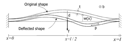
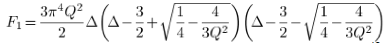
Just finished my first week. I have a lot to do. I wanted to speak with Alexis about this opposed foot design using this bistable spring. I think it might be cool, and relatively lightweight. Unfortunately, I didn't get a chance to do so. I spent some time today looking up papers on bistable curved beams. Found a really interesting one that goes into the force required to transfer from one state to another in a curved bistable beam. The beginning of the analysis is straightforward. Beam deflection equations along with buckling equations, but then the paper goes into the energy stored in the device (bending energy, compressive energy, actuation energy) and proceeds with fairly difficult math. The end result is an expression for the force required to dislodge the beam.
, where , and
(Qiu, Lang, Slocum, 2004)
Where F1 is a nondimensionalized quantity including the force f in the diagram. Q and Delta are non dimensionalized using material attributes. In short, we have an expression for the smallest force required to dislodge a curved beam from one of its stable positions. The paper also discusses higher orders of buckling, which correspond to F2, F3, and so on. We, however, concern ourselves only with the minimum force required. Cool stuff.
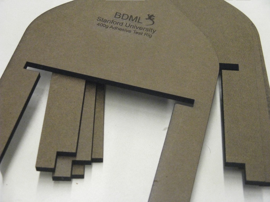
I also started to work on the new Stickybot test rig that we will send to different groups that are working on adhesion technology. I'm going to redesign the foot a bit as per what John told me. Minor changes, but requires time to become familiarized with the part in Solidworks (increase familiarity in Solidworks as well!). Got SVN up and running. I learned a bit about how SSH works, TortoiseSVN? , secureCRT, etc. Monday I'll power through some of those parts, changing the foot design and starting on the test rig.I will keep the COM to glass vs. body length ratio the same so that anyone can stick the rig on a piece of glass and accurately predict whethet their pad will work with stickybot 3.
June 21st
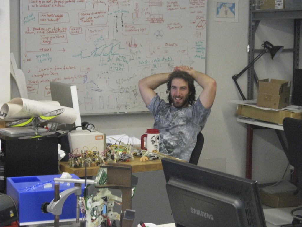
Today Mark and Alexis and I had a short teleconference with the folks at UPenn concerning adhesion methods for their quadrotor. Turns out they are interested in clinging to smooth surfaces (wood in particular). Mark suggested electrostatic adhesion. I read up on it. I don't think that we will end up working with them on a spine gripper since spines are good for only rough surfaces. I went to the SURI lunch and kickoff event. Besides the tasty calzones there was little point in attending. Samson showed me the Haas. It was a brief run through, but got me thoroughly excited about the possibilities. I worked on the Stickybot test rig for a bit. Who knew making a geometrically similar apparatus to Stickybot could require so much thought? Perhaps the most exciting thing I did today was speak with Alexis concerning feet. It has become clear to me that the way to approach complex problems with multiple avenues of solutions is to start with something that you know. In this case, we know that a given amount of shear force between the spines correlates to a normal force directed toward the wall (and hence keeping the robot clinging to the surface). The angled nature of the asperities allow for this phenomenon. So if we want to withstand a normal force pointed away from the wall, (e.g. wind force), or counteract a moment about the vertical axis of the plane, we need two sets of opposed spines loaded with a calculable amount of shear force. So while I might not know where to begin thinking about the design of a fully functional, actuated leg/foot/toe assembly for the airplane, I can at least start collecting data as to how hard do we need to pull in the vertical direction. And so I started building a little spring loaded test setup. Knowing the spring constant ,displacement, and normal force required to pull the piece off the wall, we can create a curve telling us how hard we need to pull in the vertical direction to counteract a given normal force. I played around with foam core, the existing spines, tension springs, and some wire. Hopefully soon I'll have a plot ready. Oh, and no day would be complete without an (obnoxiously large) picture of Alexis:
June 22nd
Today I spent a few hours learning about spine manufacturing. I am thoroughly inspired to start CNCing. (you can do ANYTHING!) I still need to learn how to make tool paths, and then I'll be ready. Hopefully soon. Alexis showed us how to pour. The whole SDM technique seems remarkably useful, and still simple(!) It is clear that it is an art. Alexis has his own ways (degassing slowly), while others maintain that their techniques are superior. We cut up some fish hooks, placed them carefully into the mold and poured the task 9. Tomorrow we'll do the soft material. I also worked on the Stickybot test rig for a while. It's all ready to to laserCAMM. I ordered some material today. Tomorrow I'll iron out a few issues and hopefully make a piece. Unfortunately today I didn't get a chance to test my spring loaded spine testing rig. The days seem to go by so fast.June 23rd
Spent 12 hours in the lab today. I barely got anything done! Frustrating, but I am learning. I've been playing around with SolidWorks? . I am slowly becoming more fluent and confident in creating and assembling parts. I did not accomplish my goals for the day, but I feel as though I learned as much as I could. In particular I am learning how to edit parts within an assembly. I wanted to finish building my spring loaded opposed gripper for testing but didn't get around to it. I finished a first prototype of the adhesive test rig. I became acquainted with the lasercamm in the LFL. Much easier to use than the one in the PRL. I explored the raster tool. In the PRL you have to etch and cut in two different steps. With this machine you can do it all at once. Simply change the thickness of the lines to cut. Simple. I watched (and illegally helped) Alexis finish the spines. We planed off the excess Task 9 from yesterday's pour and then cut the areas that needed to have flexible material. That took about an hour and then we poured the Vitaflex 20 (should have used 30, but we're all out). I am impressed by the fact that you can choose which urethane to use based on measured material properties (higher number = stiffer material). In theory one could have a fully defined part with known stiffness and damping coefficients. I'm even beginning to wonder if you could include stiffness as a parameter in an optimization, which would inform your decision as to which material to use. You would simply need a parametric CAD file (stiffness would be one of your parameters, potentially along with geometry), some sort of analysis tool (probably FEA), and an optimizer. Simple. (?) note to self: check out the book on bi-stable mechanisms tomorrow.June 24th
Today I finished the first full version for the test rig. the lead shot came from McMaster? . The jar broke in the package and the box came with 5 lbs of LOOSE lead shot. Unfortunately I have to say that I spent a good part of half an hour cleaning it up... I'll call tomorrow to complain. I spent a little longer than I should have figuring out diameters of holes to cut with the laser in order for screws to fit nicely. I cut the feet out of ABS. Smelled terrible in the LFL, but it cut nicely and certainly is strong. I spent an hour speaking with John and Paulo. Paulo is asking for some help with his cheap robotics platform. He mentioned that in many countries, gear sets are nearly impossible to acquire. He wants to make molds of gears to send to other countries for educational purposes. Once they have a mold they can make many batches of gears using (some sort of) plastic (Paulo mentioned a homemade glue mixture). I have my doubts... Gears seem like they need to be manufactured with high precision. From what I've seen of the casting process, proportions must be exact and the result doesn't always turn out as expected. We're meeting tomorrow to talk more.June 28th
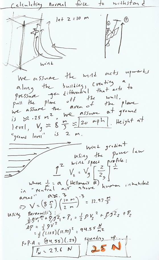
I had a productive day today. I finished making a testing device for spines to determine the amount of shear needed for a given normal adhesive force. I used the same feet structure that Alexis made previously, and included the freshly made spines (with Vitaflex 20). I put both feet on a slider (needles) so that they can only move in one direction (however some rotation did occur), and connected both feet using two springs in parallel. I determined the spring constants, and did some tests. Initially I tried the spines on the wall material of MERL. This material has very large asperities so I thought it would be a good test surface. Unfortunately the asperities are far apart so the spines don't engage quickly enough. I found two different surfaces that worked well. I used a spring scale to pull in the normal direction after engaging the spines at a certain displacement that corresponds to a shear force. Results ranged from about 1-6 N of adhesion. These numbers aren't high enough to withstand serious wind forces (rough calculations below). This is partially due to the Vitaflex 20 (instead of the stiffer 30, 40, or 50). High shear forces cause the feet to drag along the wall. If a spine catches in an asperity, and the shear force is high enough, the spine will release (due to the geometry of the spine) to avoid failure. Using a stiffer material will allow for higher shear forces and hence, more adhesion. So I replaced the new spines (20) with some of the old ones (30). I even tried using some spines with vitaflex 60 (from ZMan), but the geometry didn't fit with the feet that I had at hand. Dealing with these spines is extremely tedious. They are small, delicate, and sharp. I spent a few hours simply putting this test device together. More importantly, Alexis and I spoke about plans for the actuation of the opposed gripper. Alexis tossed around some ideas using slot mechanisms. I liked the idea of using the same overall design as the Aerovironment gripper. That is, a rotating wheel that initially pulls the spines close to the wall, then toward the other foot. We talked about how to rotate this wheel, and the possibility of simplifying the lower spines. We can use SMA wires to move the wheel, allowing for lightweight, powerful actuation. This would, of course, require some clever lever device. We also tossed around the idea of a temperature controlled circuit. Knowing the resistance of the wire, you can determine the temperature of the wire, and in order to shorten the wire without a long cooling time, you want to barely reach the temperature threshold. This is down the road... calculating the required normal force that the spines must overcome. We assume a wind speed of 20 mph (8 m/s) at 2 m off the ground. Using the wind power law profile and assuming laminar flow (not really a valid assumption given the dimensions of the airplane, but let's ignore that), we can determine the velocity of air running along the wings while it is perched on a building. Then using Bernoulli's we can determine the pressure differential on either side of the plane.
This is a very rough estimate. This ignores gusts of wind that actually flow outward from the building (not likely to happen, but should be understood nonetheless). This also assumes relatively slow air on the ground. However, the figure - 25 Newtons - is a good place to start.
A fine day.
June 28th
This morning I went to a presentation by some Ph.D students from Seoul National University. They presented some of their projects, including an SMA actuated inchworm (using folding joints modeled after origami), SMA actuated hand, poisonous starfish grabber (?), a climbing robot, and a few other projects. It was cool to learn about their methods, and manufacturing processes, although I can't say I learned a terrible amount since their English was quite limited. I spent the rest of the morning fixing Solidworks errors (I'm learning slowly) and preparing some drawings for 5 adhesive pad testing devices. After lunch I laser cut all the necessary pieces for the test rig. The laser got quite a workout today. One cut took 1:15 minutes, during which I started graphing some of my results from the shear vs. normal testing for the opposed spines. Unfortunately, and as expected, my results look random. This is due to the fact that the spines are too flexible so they release unexpectedly. I have yet to run a test with the stiffer spines. After the laser finished I started the tedious process of assembling 5 more test rigs. Got all the way through and realized that we need larger adhesive pads. The only ones available right now are about half the size of true Stickybot feet. Not sure what to do about this, but I'll just handle it tomorrow. Perhaps Saul has some extra...dddddddddddddddddddddddd
ddddddddddgoing into business dddddddddddddddddddddddddddddddddddddddddddddddd becoming a superglue wizard...
June 29th
Ugh! This project is taking much longer than anticipated. Turns out the small pads don't work for the test rig. Too much weight. The large pads work, but when I assembled the feet I used too much superglue, causing the flexures to stiffen. The target 8 degree rotation angle was not comfortably met, even with the large pads. And so, the process restarted. Laser cut more feet, countersunk the holes in the feet, and assembled them. I did very little thinking today and I am slightly annoyed with myself for being so cavalier with the superglue. As Noe said, "Let's chalk this one up for learning." So I spent almost the entire day fiddling around with stickybot feet. I am waiting to hear back from Mark to see whether we should go ahead with the small pads and decrease the weight, or if it is worth making new wide pads. If so, I'd be interested in seeing the manufacturing process for microwedges. If not, I'd be slightly disappointed since I had assumed the device would be 400g and hence, engraved a label accordingly (see above). For future reference, the geometric properties of the test rig are as follows: ratio of horizontal distance from COM to wall vs. vertical distance from COM to foot remains the same for both the robot and test device (in cm, 3:58 vs. 1.55:30 respectively). This provides identical roll-off moments. In addition, the tilt angle remains the same for both robots. I estimated that Stickybot comfortably rotates about 8 degrees in the horizontal plane. The compliance in the ankle absorbs this rotation, allowing for full contact between the pads and wall.July 1st
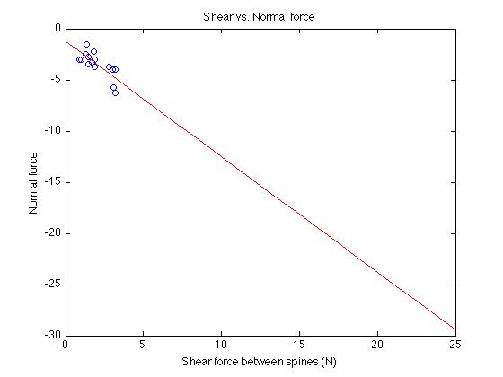
I write this from Portland. On July 1st I started a new batch of spines that will use Vyteflex 40 or 50 in order to allow more shear force before the spines hit their overload protection. I took some good notes on operating the CNC, cut about 75 fishhooks, carefully placed them in position, and poured Task 9. I've also been talking a bit with Marcus concerning the new CNC and I'm learning a little more about how the machines are controlled and how to make toolpaths. Hopefully soon I'll have a design to manufacture. I also plotted my experimental results from the shear vs. normal tests. My plots agree with the previous tests on the stage that Alexis and Alan performed earlier. This is surprising to me considering the seemingly random nature of my results. I found a linear relationship between shear force applied on a spine and normal force experienced by the spine. However, this linear relationship breaks as the spines hit their overload protection (on a cinder block this occurs at roughly 5 N of shear). Therefore, using the Vytaflex 30, and using the setup that I made, the best possible adhesive force is about 7 N. Not much... And so we are left to discuss future plans. I conjecture that using stiffer Vytaflex will help, but will most likely not allow for our desired 25 N of adhesion. I think it might be worthwhile to build a simple actuated gripper, using a servo motor for now. I worry that if I spend too much time finding the optimal force to apply in the shear direction, I won't have enough time to deal with other problems that will inevitably present themselves later on. While I am gone I will start thinking about the best way to assemble a basic gripper, much like the Aerovironment gripper. I was also given the assignment of making more feet... note to self: buy more masonite, ABS, and screws. Portland is fun!July 13th
I am back from my break. While I was gone Julia made some changes to the test rig, namely, made the foot more robust, made a box for the foot, and changed the design for bigger screws. It looks excellent now. Today Julia and I spent a large portion of the day on the laserCAMM. We assembled all of the masonite components for shipment. We still need to finish making the ABS feet. Also while I was gone Alexis did some work on landings. He has been analytically and experimentally determining possible landing envelopes given different pitch angles of the airplane. These landing envelopes are defined by vertical and horizontal velocities of the plane before impact on the wall. Obviously at high horizontal and low vertical velocity, the plane will rebound back and fall. At high vertical velocity and low horizontal velocity the plane will scrape against the wall, possibly breaking spines if the velocity is high enough. It is clear that if the plane were to have opposed spines that tightened upon impact, the likelihood of rebound would be lessened and one of the failure modes would be lessened. We could fashion a gripper by changing the flexibility of the top spines so that the plane's downward force on the wall stretches these top spines to the point where they will recoil upward, engaging the stiffer bottom spines. Simple. We would need to play around with flexibility, since this will dictate whether or not the spines will disengage by overload protection, or simply snap before getting to that point. And lastly, here is a graph of the shear force versus normal force seen by the spines (vytaflex 30) on a concrete slab. note the linearity between shear force applied and normal force seen. Also note that the max normal force seen is around -7 N this is due to the weak vytaflex, which causes overload protection to kick in.
July 14th
Julia and I finished up the AdhesiveDemonstrator today. We assembled the feet, calibrated them all correctly, helped Elliot make some more of the adhesive pads, finished the instruction page, and packed them all into boxes. We are waiting on one address and then we will be ready to ship. I also spent some time brainstorming the design of a gripper that can engage upon impact and them tighten. Need to do more of this tomorrow, hopefully with the help of Julia and others.July 15th
Finally sent off all 5 of the adhesive demonstrators. Returned to the lab just in time for another PR/collaboration related assignment. Noe wanted 6 feet to send to Draper. Back to the LFL... About 5 hours later, our work was finished. Julia and I cut and assembled 5 ABS feet complete with the newest flexures. While we worked, we were able to do some solid thinking about the actuation for the opposed gripper. I have a tentative design. Here are some thoughts (more for personal documentation):- Instead of having overload protection in the bottom spines we can use the SMA wires as overload protection. In other words, use a wire with the correct diameter such that instead of the spines failing and releasing from the wall, the SMA wires simply don't contract. Much simpler and could shave off some weight.
- Instead of having the SMA wire directly causing the rotation of a wheel that will then make the lower spines engage, we can have a system whereby the SMA wire cycles. During each cycle the wheel will rotate one click forward. We can accomplish this using a lever with one end made of a material that is only flexible in one direction (perhaps carbon fiber overhanging a stiff yet light material (another type of carbon fiber? fiberglass?). The SMA wire pulls on the other end of the lever, causing the non-flexible portion to push upward on some sort of peg, thus rotating the wheel one click. The pegs and ratchet gear teeth are, of course, equally spaced from one another such that one click corresponds to one ratchet click and one advancement. Again, this allows for as much dragging as is needed by the spine to engage.
- To release the ratchet we could potentially use the same SMA wire that is used for releasing the spines.
- Still need to think about the connection between the wheel and the carbon rod that needs to hold up the top spines. A clever connector can be designed.
July 16th
Today I redid all of the shear vs. normal tests. I used the Vytaflex 40 spines. I saw decent results. While the amount of normal force is still unpredictable, I did see clear improvement over the previous tests. The max normal force was about 10 N and that corresponded to only about 2.5 N of shear. This is, of course in only one foot. Also went to lab meeting and learned about Sanjay's artificial muscle tissue, and reaped the benefits of the first MERL summer bbq. I spoke with Mark and Elliot yesterday afternoon and I learned that it might not be a good idea to cycle SMA wires on and off. Terribly inefficient. Mark suggested a piezomotor, Elliot suggested an SMA and regular spring in series. Before landing, tighten the SMA spring, and then upon landing, let the regular spring contract, thus engaging the spines. That's all for the week.July 19th
Today I started to draw a simplified version of the gripper in SolidWorks? . It took my far too long to convert the ProE? files for the sideplates into SolidWorks? and to find the spine files. So far I think I've thought about at least 5 different mechanisms for actuation. I need to pick one and prototype. I decided that the travel along the wall is important so a simple lever that forces the spines closer to the wall will not be the best design. I am going to prototype a design involving a wheel. This was a relatively inefficient Monday, however I did try to throw my old opposed spines at a wall and they stuck pretty nicely! This bodes well for eliminating rebound during landing.July 20th
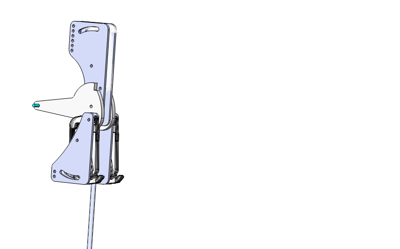
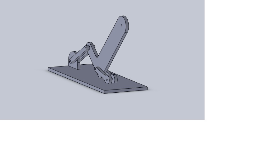
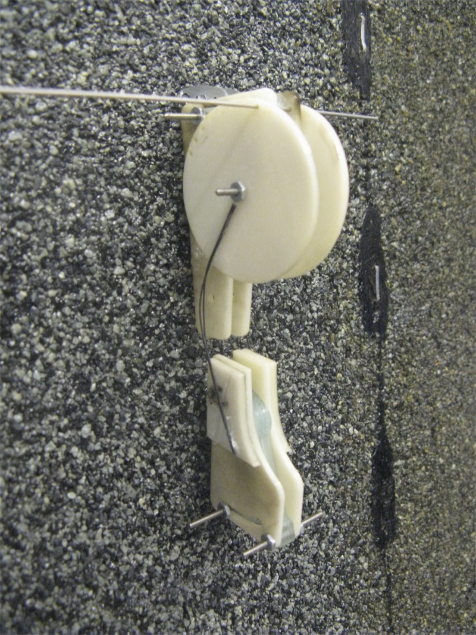
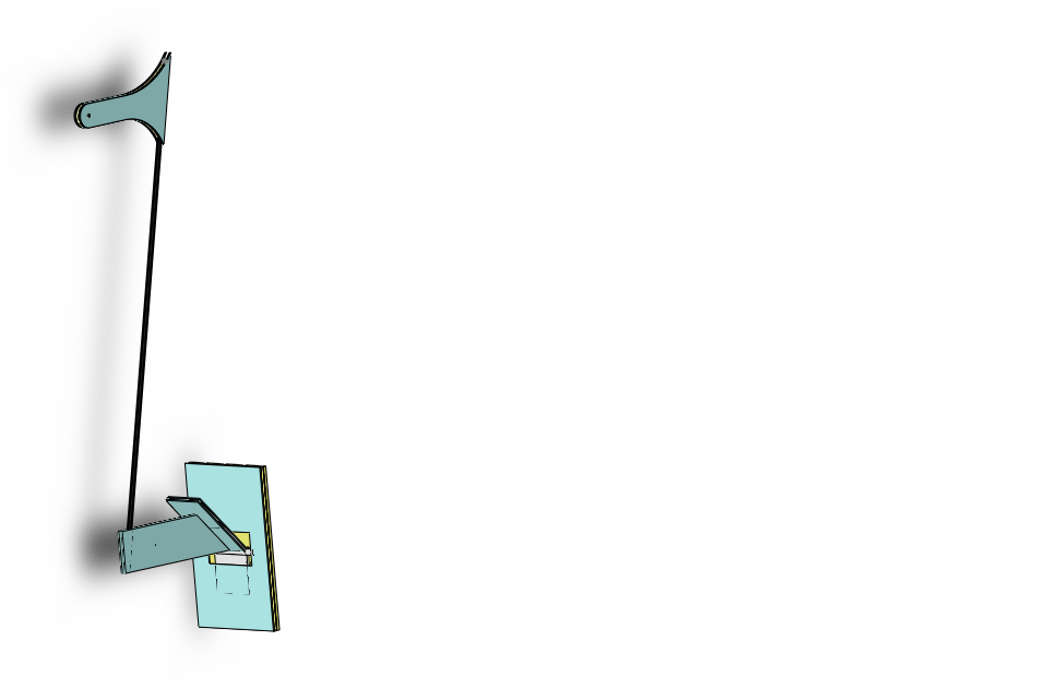
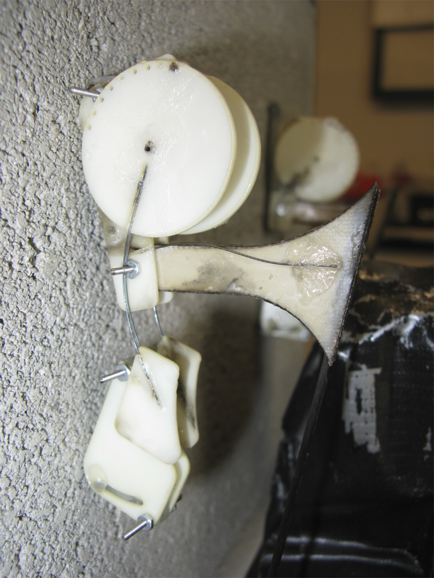
Today I spent most of the day designing and building this:
A simple version of a gripper. The device has numerous problems and is just a first pass. It showed me that I need some way of keeping the spines in the vertical direction when not in use. I'll incorporate a torsion spring to keep the lever pulled all the way back. I still need to work out the problem of not enough travel up the wall in order to engage the spines. It's also really hard to describe these things in writing. Tomorrow I'll work on a second iteration.
And today was my first MERL fire drill!
July 21st
I finally checked out Alexis' recommendation - Compliant Mechanisms (Howell, 2001) and spent a few hours flipping through and reading about how compliance is modeled. The book includes a good description of the analytical techniques used (basic elastic deformation equations coupled with torsional springs in place of pin joints). It is clear to me that compliance allows for simplicity, as the elasticity of the material eliminates the need for extra springs. The book also includes some good examples of bistable mechanisms that use compliance.
click image for animation
July 22nd
Today I started the spine making process. We are making two more sets of spines, one of Vytaflex 40 and one of 50. I also cut out some sideplates for a fixed opposable spine assembly, but can't do anything more until we make more spines. I also spent a few hours reading Compliant Mechanisms and I've begun thinking about a few 4 bar linkages that might also work for the movement of the opposed gripper. I was especially intrigued by one that results in linear motion. This particular mechanism is called a Hoeken Mechanism. I'm wondering if we can make it all out of one piece and build in compliance using flexible material along with hard material. I also spent some time looking at the analysis of the linkage. I had to leave early today to buy food for the BBQ tomorrow. The undergrads all went to CostCo? and bought unhealthy amounts of ground beef.July 23rd
I spent all morning cooking for the MERL bbq with the other undergrads. Then lab meeting went until about 2:30. Alexis gave a presentation on his optimization techniques for getting the airplane to automatically find itself within the landing envelope. He explained the different failure modes of the airplane, and how they can possibly be eliminated by some fixes and tweaks. By the time I got "to work" it was about 3. I fooled around on Solidworks for a bit trying to learn layouts for assemblies and finished making the Vytaflex 40 spines. Also stumbled across this really cool website that includes tons of clever mechanisms.July 26th,27th
SPINE MAKING - We're making some 40s and 50s Hopefully this will be the last batch of spines we'll have to make for a while. It's getting slightly tedious... I am getting very good at placing fishhooks. I've been messing around with different types of compliance for the ankle. I am building a foot with fixed opposed spines and it is necessary for the spine to orient itself (wrt vertical) on the wall. Otherwise, the top spines will engage before the bottom spines have a chance to even touch the wall. Having a set of opposed spines will hopefully eliminate rebound from the wall upon landing. And then I will focus more directly on how to tighten the spines. Implementation of this foot requires an extension from the carbon rod leg to the ankle. I've been building a few different types, all of which consist of two 1/16'' balsa sheets sandwiched between carbon fiber sheets. Super strong and lightweight. I find it challenging to work on such a small scale as any small nub of glue or a spring that is slightly too long causes fatal issues. Also, helped Marcus clean the laserCAMM, and filed a USPS claim on one of the adhesive demonstrators that didn't show up (in Berkeley nonetheless!).July 28th
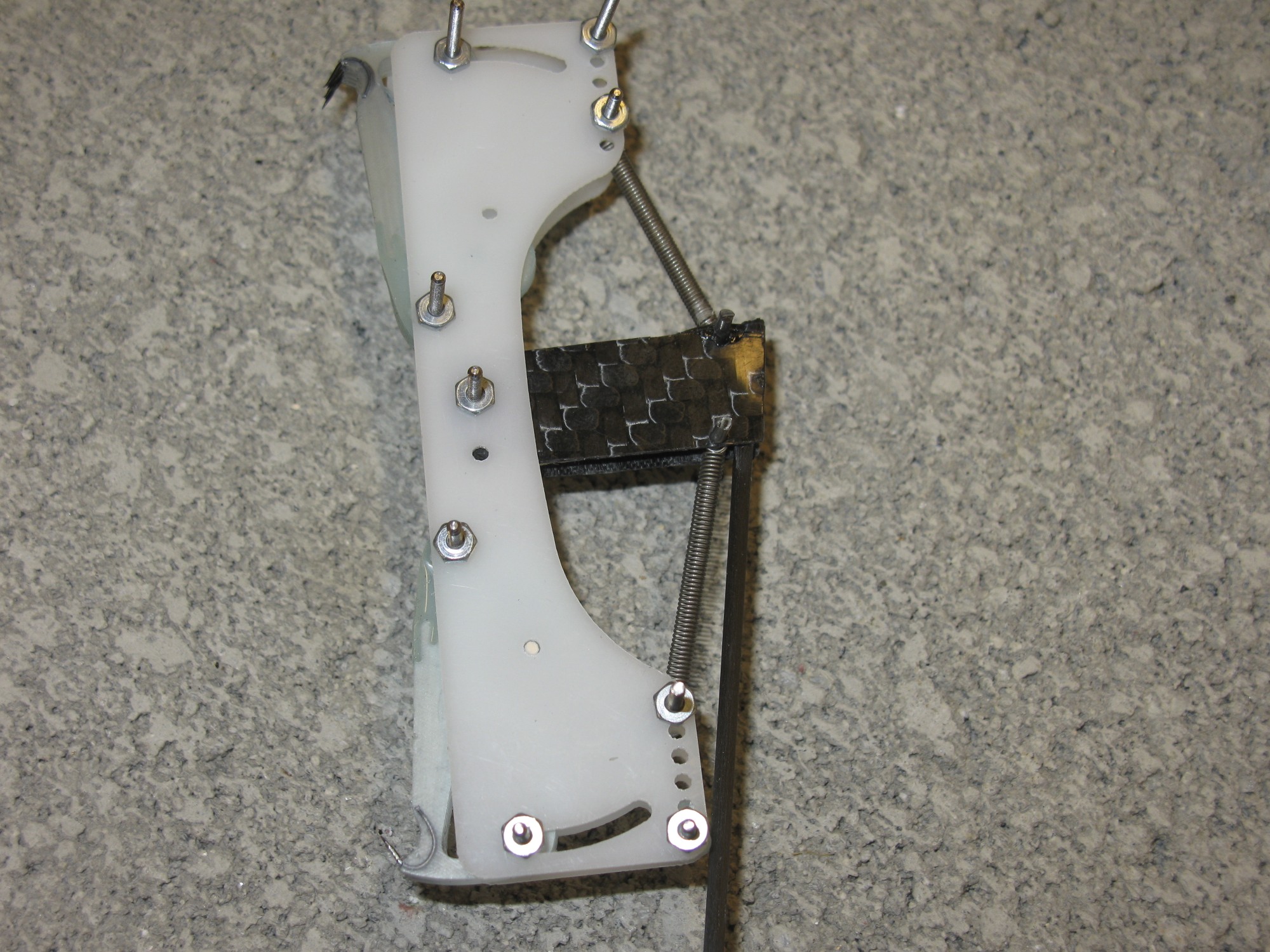
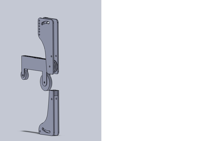
Today I spent the morning reverse engineering Alexis' hip design to build some of my own so that I can test the feet I've been working on. worked more on building the simple fixed opposed spines for the airplane for tests. I've been through a few different iterations, all of which consist of some sort of spring that holds the foot in place during flight and allows for compliance during landing. Some versions below:dddddfdfdf dddfdfdffd
In the end, the simplest design works the best. A simple piece of spring steel glued between the plastic foot and the carbon fiber leg makes up the ankle... It is very compliant and seems impossible to beat in terms of weight. I'm thinking of better ways of attaching the wire, as glue seems slightly sketchy. Solder??
July 29th-August 2nd
I finally finished the first version of my fixed opposed gripper. It took far too long to tweak the angle of attachment between the "femur" and the "hip." The problem is that the plane's COM can be too far off the wall, causing the roll-off angle to be too large, and causing the plane to pitch off the wall. On the other extreme, the suspension can actually impact the wall, causing obvious problems with the spine's engagement. This first version worked, however it needs some more tweaking before we can really say definitively whether or not fixed opposed spines will assist in extending the landing envelope. Alexis and I took some high speed video of the landings and we saw mixed results. Sometimes the rebound action of the plane will cause the lower sets of spines to engage, allowing for greater adhesion forces. Other times, the plane would rebound off the wall without causing lower spine engagement. I have also been enjoying myself on SolidWorks? , making a parametric model of a Hoeken Mechanism. All you have to do is input one link length and the rest of the model updates such that all of the spacing and dimensions remain valid. I've been trying to design around this mechanism however I am realizing that it might be too complicated to implement in such a small space. A simple compliant lever might be best... I am learning some of the powerful tools in SolidWorks? . Being able to link dimensions and equations from part to part is a useful skill. While my time spent with the software might not be directly useful for the design of this mechanism, it is worthwhile for personal gain.August 3rd
I spent today redesigning the fixed opposed spines. Turns out this requires an overhaul of the suspension system. The hinges that we have used in the past are nowhere to be found on Tower Hobbies. We have to resort to large hinges. This requires a new design for the attachment to the plane. Minor changes, but changes nonetheless. I spent some time looking at different type of fiberglass, some of which will hopefully be laser compatible. We're also looking at different types of carbon fiber to use as reinforcement to balsa. Alexis mentioned that if we could cut fiber glass with the laser, we might be able to reinforce the spines with fiberglass, and use fiberglass in other SDM parts. The new design for the fixed spines requires the angles of the hip/femur attachment and femur/ankle attachment to be precise. They are created in such a way that the spine sideplates are parallel to the wall when landing and the airplane hangs close to the wall. I listened in on Noe explaining in detail the manufacturing process for the dry adhesive molds, and did a study for the CDR.August 4th
Built yet another prototype for a gripping mechanism. Started on SolidWorks? .
I quickly realized that we need to know the diameter of the wheel before being able to go any further. This, of course hinges upon how hard we need to squeeze, which depends on how much adhesion we need.
Alexis ran by some ideas about how to find a better approximation for the forces that the plane needs to be able to withstand. We also talked about how it would be nice for the opposed spines to open upon impact and then close automatically. I will start to build a normally closed gripper with adjustable closing angles.
August 5th
Today I revised our initial approximation for how much normal force the feet should be able to withstand. Alexis showed me a way to approximate lift and drag coefficients for a "flat" plate angled away from flow. Of course, once we know these coefficients, we can solve for the lift and drag forces for each of the four possible orientations of the plane on the wall. I solved the free body diagram for each of the four cases (wind traveling up, down, left, or right across the wall), and found that given a 25 mph wind (a "strong breeze" on the Beaufort Scale), and using the geometry of the plane, we will need about 12 N of normal force. You can find my calculations here (or on Yoda) . You can input any wind speed and see how much holding force is required. I also started building a set of opposed spines whose bottom set is angled inward toward the wall. I made the angle adjustable at 10 degree increments. The lower spines will be attached using NiTi? wire. Hopefully, we see the feet grip upon impact. I am realizing that building anything for this airplane is very hard due to the fact that everything is fairly unpredictable. The landing motion is not predictable. We have to build and try, build and try. This project is going slower than I had expected. I have yet to actuate any spines with SMA. Of course, I also understand that before building any formal sort of foot we need to really understand what is happening upon impact. The process takes time!August 9th
Finished making the Vytaflex 50 spines. They didn't come out as well as some of the other versions have. The 50 is not as stiff as I had hoped. It is very damped, but not necessarily stronger than the 40 or 30. I think this will be my last spine making endeavor of the summer, as we now have 20s, 30s, 40s, and 50s. I would like to try 60s, but I don't think it's worth it. I had a short day today. I was running on a few hours of sleep over the course of the whole weekend (camping trip), so I left a bit early. I started putting together an outline for a poster, and I assembled the angled fixed opposed spines. I ran into a few problems: NiTi? wires are great flexures, but they flex in every direction. I need to find a small and compact way of restraining their motion to a plane. I disassembled the first version and made another using CA hinge (attached in between two wires), but this was too bulky and the foot didn't grip very well upon impact.August 10th
I think we are honing in a feasible design for the gripper. I built yet another normally closed gripper with NiTi? flexures. This version sticks fairly well without any internal squeezing force. I will refine this version and eventually mount it on the plane.
Alexis and I had a long discussion about goals. I want to have three things accomplished in the next three weeks:
* Prove that this opposed gripper design extends the landing envelope (avoiding rebounds)
* Get some data showing that the airplane can withstand wind gust forces
* Get a time-lapse sequence of the plane sitting on the wall of a building for a long (multiple day) period.
In order for this to happen I will do the following:
spruce up this current design. That means ensuring rotation within a plane, modifying the sideplates a bit, and modeling the flexure as two rigid bodies with a torsion spring connection. I need to pick a reasonable force with which to squeeze. This involves testing the validity of Alexis' limit surface graph. I also need to choose a method of actuation. I'm considering SMA springs, or a regular SMA wire with ratchet system.
August 11th
I spent the day creating a model that predicts the forces on the spines given different spine stiffnesses and different distances between spines and ankle attachment point. I basically have been doing statics most of the day. I also discovered that we can laser cut .01'' fiberglass! This will make for some super strong (and easy to build) legs and hips. Tomorrow I'll start making more legs and feet.August 12th-16th
Oh boy I wish I had another month of summer... I have so much that I want to do and each thing that I do seems to take twice as long as I had anticipated. I have a design that seems to be working well. There are a few improvements that I would like to see, but I'm focusing on putting these legs on the airplane to see how they hold up. I've been making more spines (...) in order to build more test feet. Unfortunately one of the batches of spines was a total failure. The Task 9 didn't cure correctly and it appears that the wax block we were using was not planed perfectly flat (curious). That was a big waste of time. Alexis and I have since started another batch. I think by now I've built about 5 or 6 versions of this normally closed gripper. I've been tweaking angles, connections, etc. I'm currently trying to model the curvature of the NiTi? flexure to be able to decide where to make the attachment.
I spent most of the day today (16th) building a new suspension system. The new fiberglass that I ordered is able to be cut on the laser, making for extremely strong and convenient pieces. I'm doing 1/16'' Balsa sandwiched between two .02'' pieces of fiberglass from ACP composites. If I had another month of summer I'd love to do some stress testing for this composite. It's incredible strong for it's weight.
In building new legs/hips, I've discovered that Tower Hobbies no longer carries the small version of the hinge that makes up the hip. I ordered some large ones and am currently redesigning the suspension to account for the large hinge.
August 17th
I spent a good part of the day cutting and placing fish hooks for about 100 new spines. I poured. I also finished one of the airplane legs and attached one of the feet. The foot is attached to the leg with a compliant ankle. The flexure is made of NiTi? and allows for rotation about the ankle joint. I spoke with Alexis about the foot design and we have some improvements, but before I can act on those I need to make another identical foot and leg so that we can test the concept on the airplane. One large problem that we see is that the lower set of spines seem to twist upon impact with the wall. We haven't tested this yet on the plane, but just by hitting the spines against tarpaper, it seems like this might be a problem. There is no clear solution in my mind to make the flexure unidirectional. (note: now I see why climbing birds have that toe that is angled off to the side. see one of my first posts.) Building takes so much longer than it should...August 18th
I mounted the two new legs on the plane, complete with two sets of normally closed feet. I did some informal tests, took some high-speed video, and discovered a number of things- We are trying to change too many variables at once. With the complicated behavior of the spines, we need to change one variable at a time. I added ankle compliance, the lower set of spines, new sideplates, and a new suspension all at once. It didn't work very well.
- We need to address the problem of twisting flexures on the lower spines. The NiTi? is too soft in every direction. Alexis and John and I talked about the flexure that John used in the Aerovironment gripper. It seems to be a bit bulky for our purposes, but definitely solves the problem of unidirectional flexion.
- It would be nice to have a system to easily change out spines. The spines break after about 10 trials. Also, for the next batch we need to thicken the task 9 on the spines in order to reinforce the spines.
August 19th
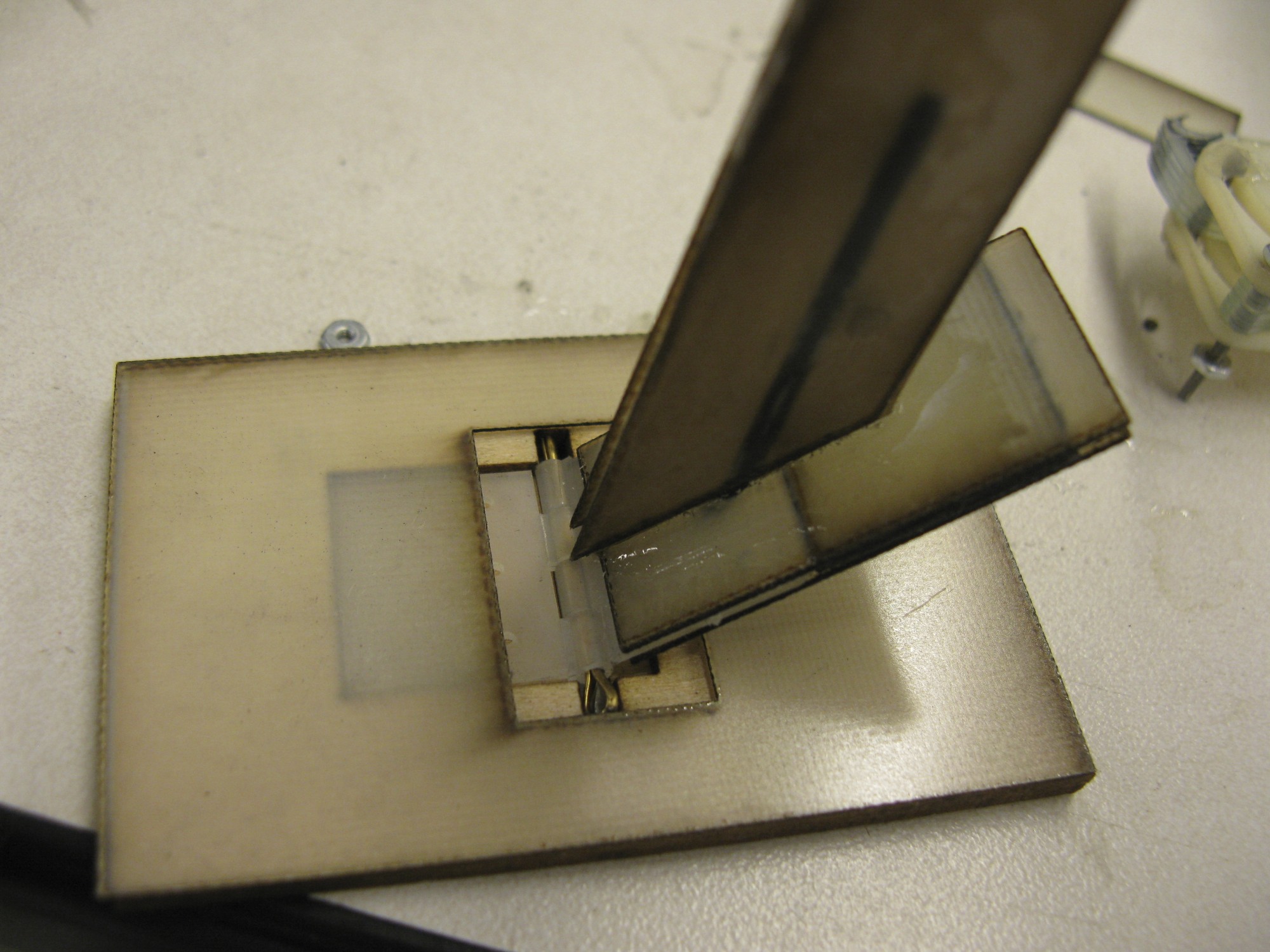
I finished making the newest set of spines today. I also worked on a different type of flexure that Alexis came up with yesterday. It involves two parallel strips of fiber glass, one of which is free to slide, the other of which is glued in place. This flexure holds up well in torsion and only flexes in one direction. The only drawback I see is that the fiber glass is not perfectly elastic, so after a few cycles, it begins to deform. I made a few versions of this today and thought about how to mount it between the top and bottom spines.August 20th-25th
I've made another foot prototype. This one is extremely compact, as the flexure sits in between the lower and upper spines. I think this will be my 7th or 8th foot prototype.... It's a shame that none of them have really worked very well. I've realized that I am basically trying to reinvent the Aerovironment gripper and make it much smaller. The main difficulty is the flexure. We need something that is stiff in every direction besides one and it must have an extremely small bending radius. The sliding flexure that I was working on before does work, but I worry that it might be too soft. Making them is a real pain, as they are very small and gluing anything that small is never easy. I'm also working on my poster. I think it will contain many pictures of foot prototypes, a little bit of information on significance, inspiration (from woodpecker feet), and some analysis.Ideas, requests, problems regarding TWiki? Send feedback