new web: http://bdml.stanford.edu/pmwiki
TWiki > Haptics Web>StanfordHaptics > PhotonicRobots>Prototype35 (02 Mar 2007, YongLaePark)
Prototype 4
Design and Fabrication improvement
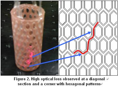
One critical limitation to embed multiple FBG sensors which the previous prototype showed was high optical loss from sharp bends of the embedded fiber. If there are only one or two sensors embedded in the structure, optical loss is not a big problem. However, the more sensors are embedded, the higher optical loss the structure experiences from more sharp bends during the embedding process. This limitation made the I-Sense interrogator difficult to read different sensor signals from multiple sensors although it has a good ability of multiplexing and de-multiplexing. Figures 1 and 2 show where the embedded fiber experiences the optical loss when a red light is shined through the fiber in a sample shell structure. Three fibers are embedded and spliced to one in the structure. Two major causes are observed in the sample: too narrow space between patterns and sharp corners of hexagons.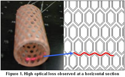
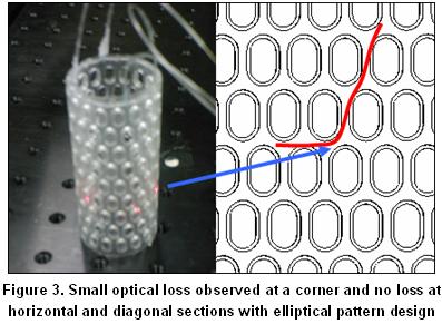
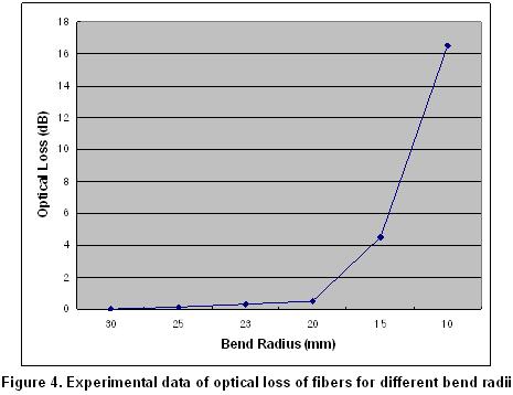
 This optical loss could be reduced by having elliptical patterns instead of hexagonal patterns as shows in Figure 3. The ellipses not only allow more room between patterns but also eliminate the sharp corners. It is clear that both horizontally and diagonally embedded parts are almost straight lines. The only optical loss observed is round corners of ellipses, but the loss in this part is much smaller than that of hexagonal patterns. The regular fiber used for prototype fabrication currently can be bent with an approximate radius of 25mm [1] for no optical loss. However, the optical loss increases almost exponentially as the radius decreases. Experimental data of the optical loss for different bend radius are shown in Figure 4. The first sample shown in Figure 1 showed more than optical loss of 25 dB, but the second sample in Figure 3 showed optical loss less than 2 dB.
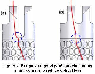
 Another design change made to reduce the optical loss in this stage is joint part modification of the finger prototype. The previous prototype did not have enough space for fibers to go out of the structure without serious bends as shown in Figure 5.a, but the new prototype provides more room at the connection between the shell and joint shown in Figure 5.b. This change reduces the optical loss too.
 Even though the optical loss from sharp bend can be reduced from physical design changes of the prototype, it is not desirable to constrain the design itself since the shapes and dimensions of robot parts will vary significantly for different robots. Therefore, it is inevitable to eliminate or at least loosen design constraints from sensor properties. As part of this effort, bend insensitive fibers are under investigation*. These fibers allow the bend radius up to 10mm which is less than 50% of the radius regular fibers allow. As soon as the feasibilities are validated, they will be used for the next generation of the finger prototype. The bend insensitive fibers are expected to allow FBG sensors to be embedded in even smaller and complicated robot parts.
* BIF-1550-L2 / BIF-RC-1550-L2,
Even though the optical loss from sharp bend can be reduced from physical design changes of the prototype, it is not desirable to constrain the design itself since the shapes and dimensions of robot parts will vary significantly for different robots. Therefore, it is inevitable to eliminate or at least loosen design constraints from sensor properties. As part of this effort, bend insensitive fibers are under investigation*. These fibers allow the bend radius up to 10mm which is less than 50% of the radius regular fibers allow. As soon as the feasibilities are validated, they will be used for the next generation of the finger prototype. The bend insensitive fibers are expected to allow FBG sensors to be embedded in even smaller and complicated robot parts.
* BIF-1550-L2 / BIF-RC-1550-L2, PureAccess /
Available: http://doclib.corning.com/OpticalFiber/pdf/pi1463.pdf [2]
Available: http://www.stockeryale.com/o/fiber/products/bif-1550-l2.htm [3] Sumitomo Electric U.S.A., Inc., Bend Insensitive Single Mode Fiber,
Available: http://www.sumitomoelectricusa.com/scripts/products/ofig/hpcfhg.cfm#pureaccess -- YongLaePark - 02 Mar 2007
Ideas, requests, problems regarding TWiki? Send feedback