new web: http://bdml.stanford.edu/pmwiki
TWiki > Haptics Web>StanfordHaptics > PhotonicRobots>Prototype1 (07 Jun 2006, YongLaePark)
Prototype 1
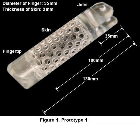
Based on the design concept, an exoskeletal robot finger with honeycomb pattern skin structure has been designed and fabricated as a first prototype based. The first prototype proved the linearity of the system as a force sensor. The hysterisis of the prototype showed the necessity of temperature compensation in the next prototype. The first prototype and its dimensions are shown in Figure 1.
1. FEM Analysis of Skin Structure
Before starting fabrication, finite element analysis has been conducted to investigate the structural characteristics using a commercial software package, COSMOS Works®. This analysis helped to predict how the structure will deform and where stresses and strains will be concentrated when different types of forces are applied. The FBG sensors are embedded based on the result of this analysis. Figure 2 show the strain distributions when different directional forces are applied on the fingertip. When horizontal forces are applied, most strains are concentrated at the top of the skin structure which is connected to the joint - Figure 2(a). However, the strains are uniformly distributed over the skin if vertical forces are applied at the bottom of the fingertip - Figure 2(b). Therefore, it is easy to distinguish the directions of forces.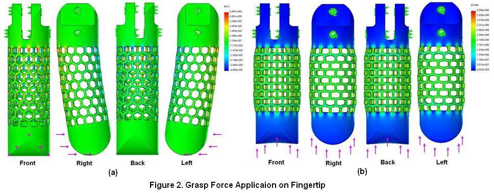 Figure 3 shows the strain distribution when a point force is applied on the skin. The direction of the force is perpendicular to the skin surface. The top of the skin takes most of strains except the adjacent area of the force. The strains also appear diagonally. These results show the top part of the skin is one of the good candidates to put FBG sensors.
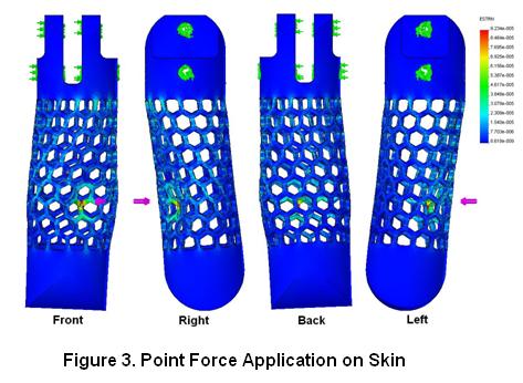
2. Fabrication Process
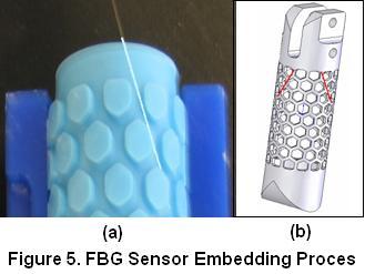
The first prototype has been built by casting polyurethane in custom made molds. Figure 4(a) shows the molds used to make the prototype. The finger can be divided into three parts, joint, skin, and fingertip as shown in Figure 1. The skin part is made first, then bonded to the fingertip, and finally to the joint during the subsequent castin proceses. Figure 4(b) shows the three steps of building the finger. The FBG sensors are embedded during the first step as shown in Figure 5(a). Based on the FEM analysis discussed in the previous section, two FBG sensors are embedded at the top of the skin diagonally as shown in Figure 5(b). However, one sensor has been broken during the extracting process.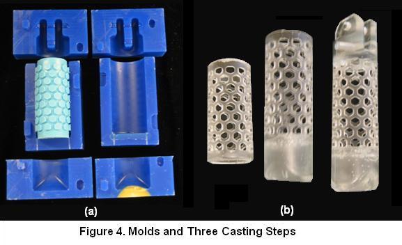
3. Force Sensing Test and Analysis
Since one of the two embedded sensors is broken, all the tests were performed with only one sensor. Three different types of tests have been conducted: thermal drift test, vertical force application on the finger tip, and point force application on a specific spot of the skin. 3.1 Thermal Drift Test Since it is critical to check the thermal effect to characterize a strain sensor system, thermal drift test has been carried out. The embedded sensor was connected to the receiver system and left alone for three minutes in each test. Figure 6 shows four different test results. The thermal drift turned out to be significant even in room temperature. Test 1 result shows much larger strain difference between the minimum and the maximum than those of the others. The reason is that the finger had been touched for a while by experimenters hands for test set up before the test, but the other three tests were conducted with much shorter contact of experimenters hand. The test results confirm that reliable temperature compensation is necessary to isolate thermal expansion from strain change.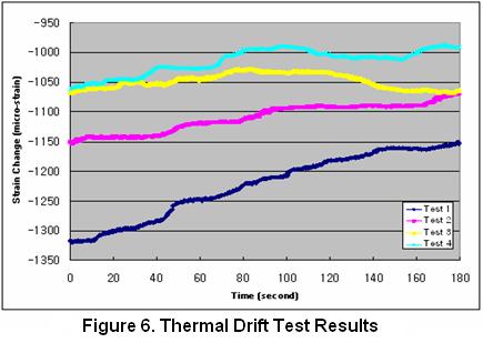 3.2 Vertical Grasp Force Test
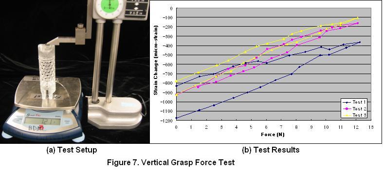
The next test conducted is vertical force application on the finger tip, which is the same as the second FEM simulation shown in Figure 2(b). Since only one sensor is available, the main objective of this test is to examine the linearity and the hysteresis in the force-strain relationship. Incremental forces were applied on the finger tip up to about 12N, and the force was decreased back to zero gradually. Figure 7 shows the test setup and the results. The three identical tests have been carried out, and the strain changes have been recorded depending on the force changes. Each test took about 10 minutes. Hysteresis appears in all three tests. However, most of this hysteresis is considered to be caused by the thermal drift shown in the previous test. Therefore, if the thermal drift can be eliminated, the hysteresis is expected to decrease significantly and the applied forces will be predictable since the slope of the plot is close to linear.
3.2 Vertical Grasp Force Test
The next test conducted is vertical force application on the finger tip, which is the same as the second FEM simulation shown in Figure 2(b). Since only one sensor is available, the main objective of this test is to examine the linearity and the hysteresis in the force-strain relationship. Incremental forces were applied on the finger tip up to about 12N, and the force was decreased back to zero gradually. Figure 7 shows the test setup and the results. The three identical tests have been carried out, and the strain changes have been recorded depending on the force changes. Each test took about 10 minutes. Hysteresis appears in all three tests. However, most of this hysteresis is considered to be caused by the thermal drift shown in the previous test. Therefore, if the thermal drift can be eliminated, the hysteresis is expected to decrease significantly and the applied forces will be predictable since the slope of the plot is close to linear.
 3.3 Skin Contact Force Test
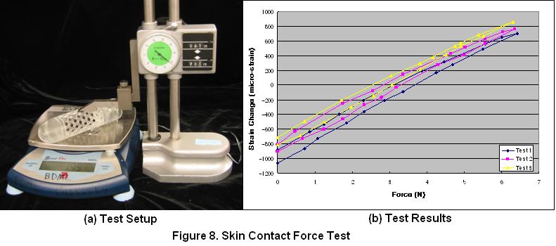
The last test is point force application at a specific spot on the skin structure, which is the same as the last FEM simulation shown in Figure 3. In the same way with the previous test, forces were loaded incrementally up to about 6.5N and unloaded back to zero slowly. Figure 8 shows the test setup and the results. Three identical tests have been conducted and corresponding strain changes were recorded. The results show the system is very close to linear. Hysteresis appears again but smaller than that of previous test. It is due to the shorter experimental time (7-8 minutes) and the smaller maximum force applied. This hysteresis is also expected to decrease considerably if the thermal expansion can be eliminated.
3.3 Skin Contact Force Test
The last test is point force application at a specific spot on the skin structure, which is the same as the last FEM simulation shown in Figure 3. In the same way with the previous test, forces were loaded incrementally up to about 6.5N and unloaded back to zero slowly. Figure 8 shows the test setup and the results. Three identical tests have been conducted and corresponding strain changes were recorded. The results show the system is very close to linear. Hysteresis appears again but smaller than that of previous test. It is due to the shorter experimental time (7-8 minutes) and the smaller maximum force applied. This hysteresis is also expected to decrease considerably if the thermal expansion can be eliminated.
 3.4. Conclusion
As a result, these tests confirm that the first prototype with an embedded FBG sensor yields relatively high linearity when different forces are applied. Although the prototype shows some hysteresis too, it is expected to reduce significantly if a robust temperature compensation method could be implemented. Creep may be another reason of the hysteresis, but it was not able to examine easily how critically creep affects the current system without the temperature compensation. Creep of the material will be taken into account more in detail in the next prototype after eliminating the thermal effect.
-- YongLaePark - 01 Jun 2006
3.4. Conclusion
As a result, these tests confirm that the first prototype with an embedded FBG sensor yields relatively high linearity when different forces are applied. Although the prototype shows some hysteresis too, it is expected to reduce significantly if a robust temperature compensation method could be implemented. Creep may be another reason of the hysteresis, but it was not able to examine easily how critically creep affects the current system without the temperature compensation. Creep of the material will be taken into account more in detail in the next prototype after eliminating the thermal effect.
-- YongLaePark - 01 Jun 2006
Ideas, requests, problems regarding TWiki? Send feedback