new web: http://bdml.stanford.edu/pmwiki
TWiki > HSR Web>HumanSafeRobot>ControlAndDynamicModeling (28 Feb 2008, BarrettHeyneman)
Control and Dynamic Modeling
The Team:
- IreneSardellitti?
- BrianHachtmann?
- JasonReid?
- DanAukes
- SeokchangRyu
- BarrettHeyneman
- JohnUlmen
Current Work:
Basic Joint Control- Stability and performance
- Bone and Skin Sensor Response Modeling
- Estimation of expected Bone and Skin sensor inputs
- Safe Response
DM2 Controller Design Methodology
Irene has been working on the higher level control of the DM2 actuation scheme (i.e. assuming the Macro and Mini both have their own inner closed loop controllers), and for the last few weeks I (Barrett) have been helping out. Experiments showed two undesirable effects: a low bandwidth on the overall control of the arm, and (for higher amplitude/frequency combinations) eventual instability. Irene's thought was: perhaps we are hitting the torque limits of the Mini, and as a result we are seeing this undesirable behavior. So, what happens if we include a saturating element in series with the Mini? And how can that inform the design of the controller; both the outer, DM2, controller as well as the inner Macro or Mini controllers. The block diagram of the system with the saturation is shown below (the transfer functions in the blocks are just place-holders from simulink).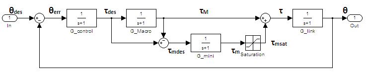 The basic assumptions are:
 - The Macro can provide large enough torques that we assume no saturation. It will have a low bandwidth relative to the desired arm trajectories, so the closed loop Macro is assumed to act like a low-pass filter.
- The Mini has a much higher bandwidth; high enough relative to the desired arm trajectories that we can consider it a unitary gain. The torque limits are captured in the series saturating element.
- The Macro and Mini are connected in the parallel DM2 scheme (captured in the block diagram structure).
Basic Design Method
First we need to add the saturation to the model analytically; we're using Describing Function analysis to do that. (Anyone who's not familiar can find lots of information on the web; basically you describe a nonlinear element as a linear element which changes gain/phase based on input amplitude, not input frequency). For a saturation element, the describing function (below) gives a variable gain, between 0 and 1, based on the input amplitude.

The Design Tradeoff
One method we've been trying is to pick a minimum value for N(a), such that 0 < K_min <= N(a) <= 1. Then we can design a controller for the new "worst case", when N(a) = K_min, and do input shaping to ensure N(a) >= K_min. The value we choose for K_min is the parameter which controls the high-performance vs. restricted input tradeoff. Once we have the value of K_min, we perform two steps; designing the controller and characterizing the required input shaping.Controller Design
The controller design is the easiest step. We simply set the Mini and saturating element to a gain of K_min, and design a controller based on this. It may be useful to also look at how different controllers which are stable for N(a) = K_min perform as N(a) -> 1.Input Shaping
Once we have a controller, we need to have some function which maps the amplitude and frequency of the input and the saturation limit of the Mini, tau_sat, to the value of N(a). We can then use this function to limit the frequency content of the input trajectory so that N(a) >= K_min. One method which looks promising is to:- "Break" the system by removing the Mini and saturation element. This makes the system 2-input-2-output, where the inputs are the desired trajectory, Theta_des, and the saturated Mini torque, tau_ms and the two outputs are the actual trajectory, Theta, and the unsaturated Mini torque, tau_m.
- We assume that tau_ms is saturated and therefore specify the amplitude.
- The easy but less accurate saturation amplitude is simply tau_sat.
- A more complicated (and not yet explored) saturation amplitude would be a function of tau_sat and the amplitude of tau_m.
- We then find the transfer function from Theta_des and tau_ms to tau_m (the transfer function for Theta doesn't help us here).
- Because the saturating element that we removed is a pure gain, i.e. no phase change, we know that the phase of tau_m and tau_ms must be the same.
- We then use this transfer function and the equal phase restriction to set up two equations relating the amplitude and phase of tau_m to the amplitude and frequency of Theta_des and the saturation torque, tau_sat.
- Once we solve for the amplitude of tau_m, we can either use the describing function, N(a), directly or (to be more consistent with the choice is step 2) the ratio of |tau_ms| to |tau_m| to get N(a) as a function of the amplitude and frequency of Theta_des and tau_sat.
Ideas, requests, problems regarding TWiki? Send feedback