new web: http://bdml.stanford.edu/pmwiki
TWiki > HSR Web>HumanSafeRobot > SkinDesign>ConductivePolymerTest (15 Apr 2008, SamsonPhan)
-- SamsonPhan - 15 Apr 2008
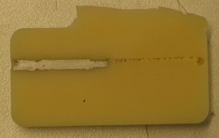
I successfully filled and planed the conductive epoxy filled groove. After pulling the part out of the mold, I manipulated the flexible urethane, which resulted int eh cracking of the conductive epoxy. The bond between the two materials was rather weak. as well.
 -- SamsonPhan - 02 Apr 2008
I got interested in etching conductive paths on the soft urethane. If possible, we would be able forego the joints and replace them with flexures with conductive paths. The flexures would ease the difficulties involving passing electrical conduits through the joint.
Planing of Vytaflex 60 can be done, albeit very carefully at low speed (feed rate 10%). To ensure that the machining path is clear, it is necessary to pass through the area twice, in opposite directions. Note that the resultant path is much larger than the tool bit itself.
-- SamsonPhan - 02 Apr 2008
I got interested in etching conductive paths on the soft urethane. If possible, we would be able forego the joints and replace them with flexures with conductive paths. The flexures would ease the difficulties involving passing electrical conduits through the joint.
Planing of Vytaflex 60 can be done, albeit very carefully at low speed (feed rate 10%). To ensure that the machining path is clear, it is necessary to pass through the area twice, in opposite directions. Note that the resultant path is much larger than the tool bit itself. - Attempt to mill soft urethane after planing. The mill was placed in the middle, then proceeded south before returning north. The path that was milled twice can be clearly differentiated from the tool path that was milled only once:
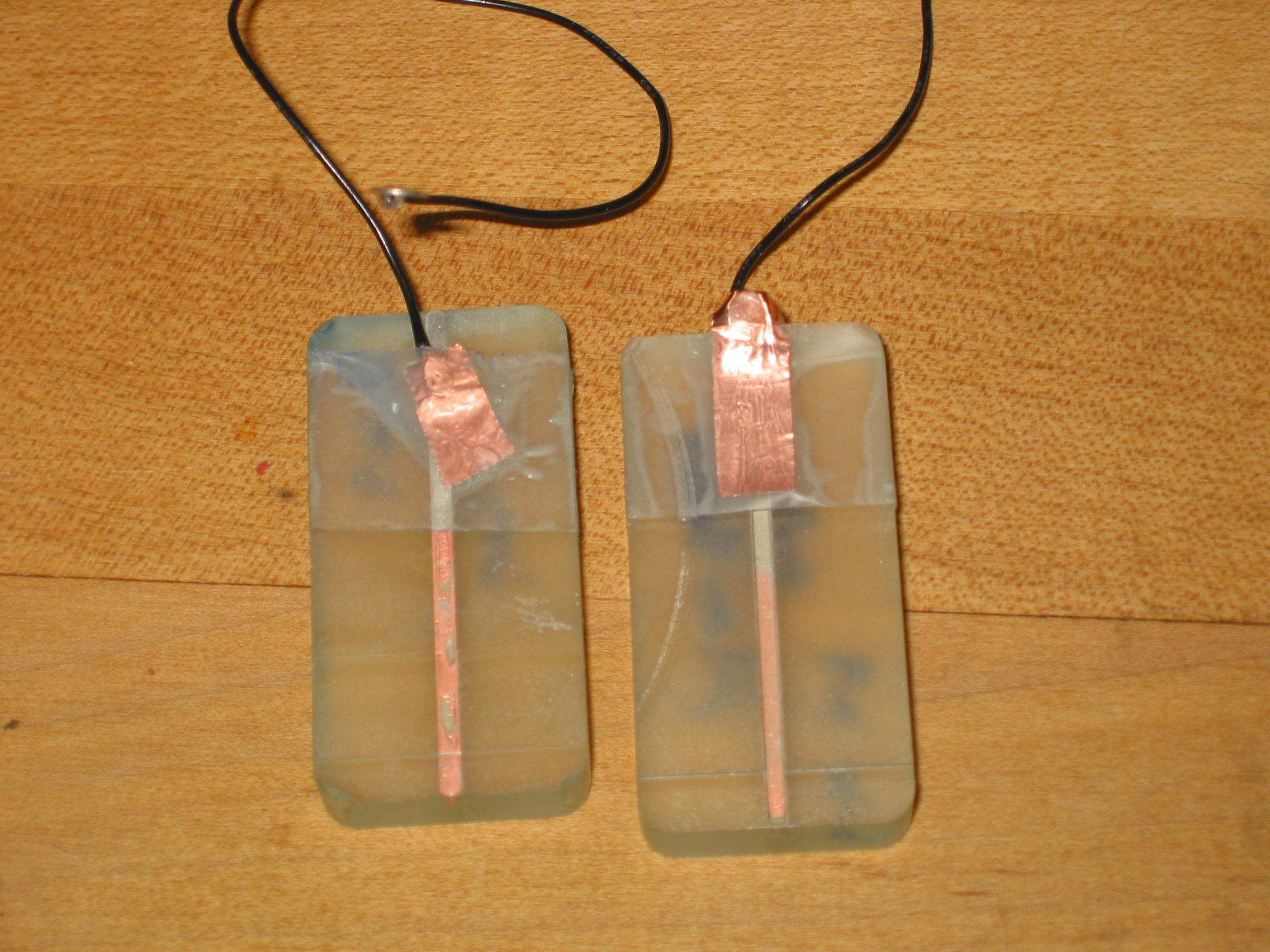
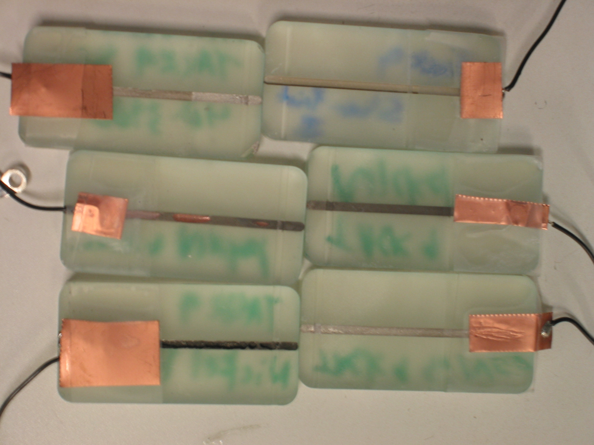
- Succesful samples:
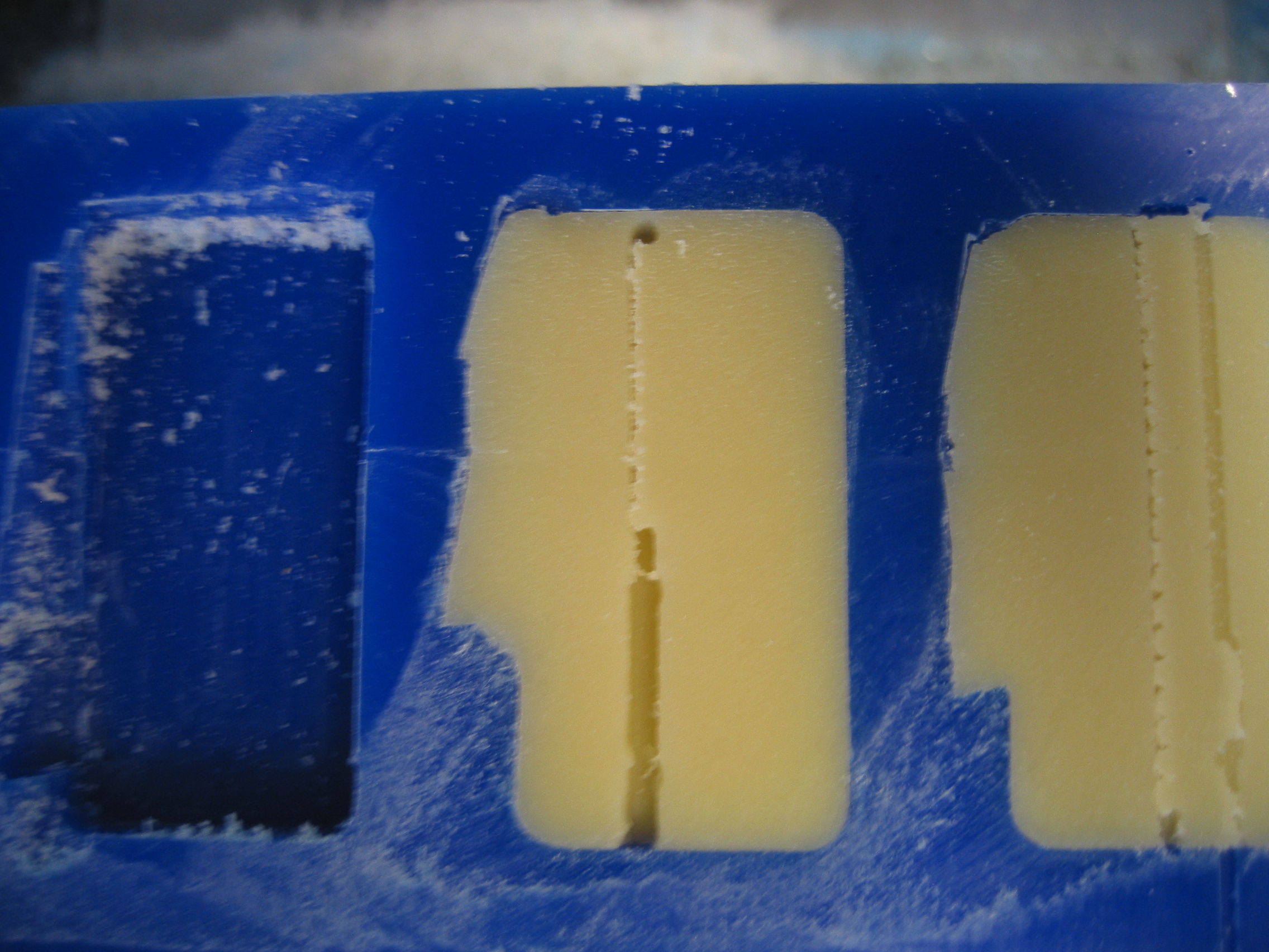
- Joint closeup:
- Before electrodeposition:
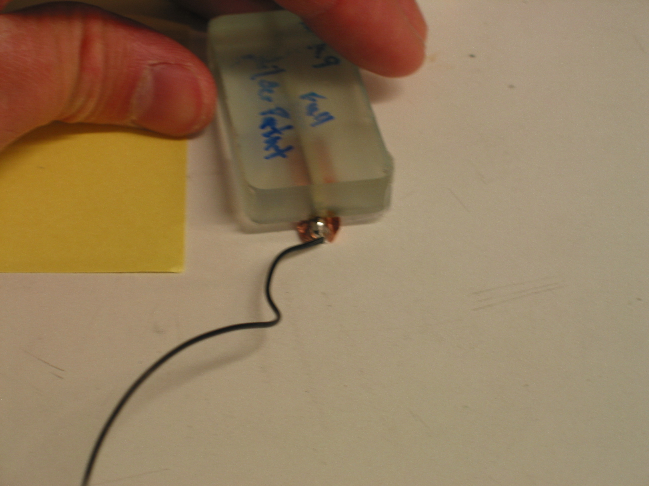
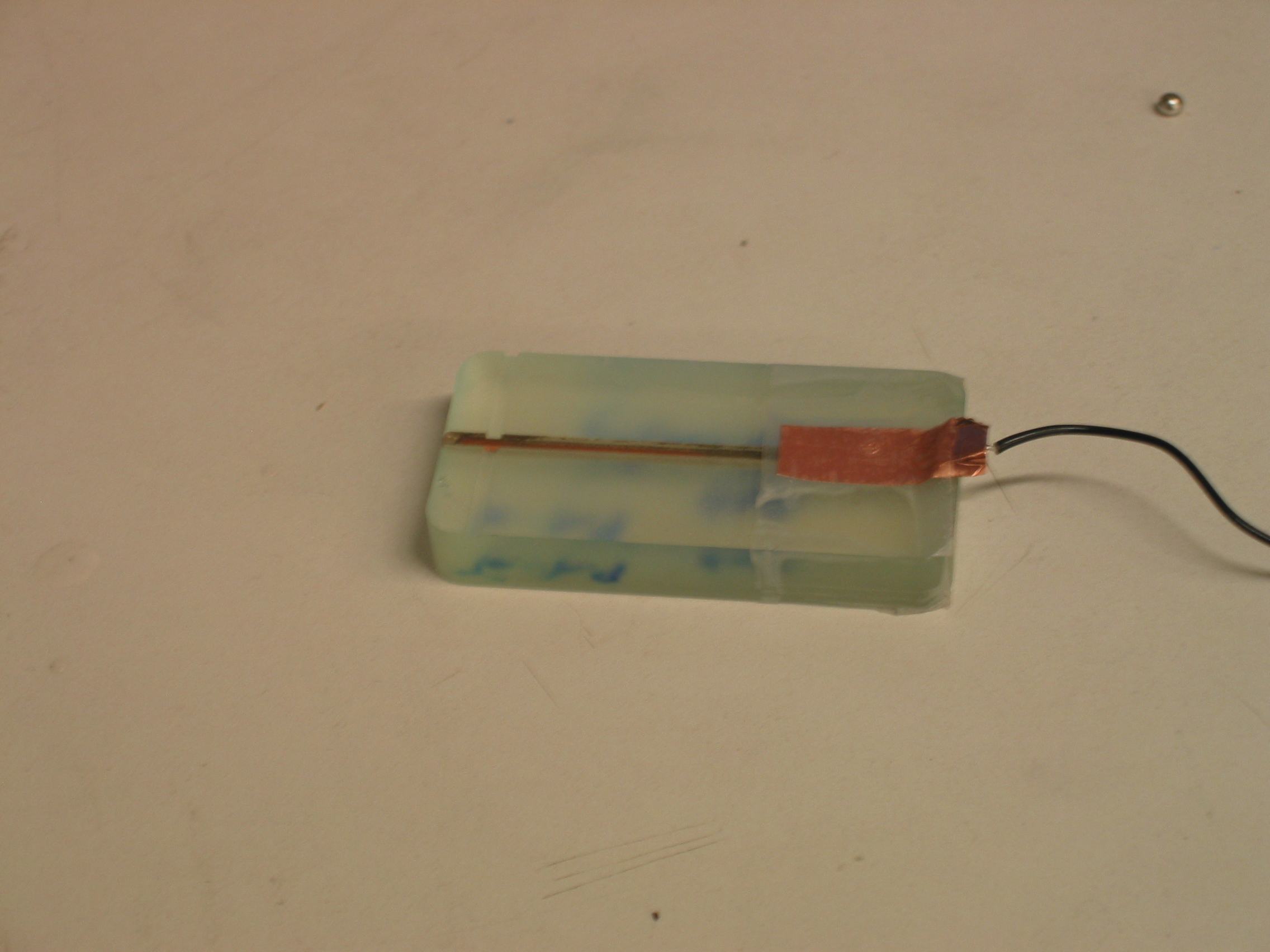
- Silver Print Sidewall:
| Name | Resistance 3/17/08 | Resistance 3/19/08 | Resistance 3/20/08 (post electroplate) |
|---|---|---|---|
| Conductive Epoxy (from Physics Store) | 0.8 | 0.6 | 0.3 |
| Nickel print (from Physics Store) | 4 | 5.2 | |
| Nickel Epoxy (from Epoxies etc) | No reading | No reading | |
| Nickel Epoxy Sample 2 (from Epoxies etc) | No reading | No reading | |
| Silver Epoxy (from Epoxies etc) | 4.5 | 8.5 | |
| Silver Epoxy Sample 2(from Epoxies etc) | Variable | Variable | |
| Silver Print (from Physics Store) | 0.5 | 0.5 | 0.3 |
| Silver Print Sample 2(from Physics Store) | 1.9 | 2.0 | |
Ideas, requests, problems regarding TWiki? Send feedback