Dual Mode Capaciflector and Tri-Slope Conversion
|
Contents:
|
 This page is under construction. To Do list: This page is under construction. To Do list:
- More on coupling section
- dual slope conversion picture/equation? (accuracy and time)
- picture of dual slope with switched capacitance (and equations?)
- Accuracy comparison for large and small steps
- Picture of full tri-slope conversion
- pictures of coupled simulations; not switching together, small C_cpl, large C_cpl (for two values of Cx), voltages and charge transfer
|
--
BarrettHeyneman - 05 Aug 2008
Technology Overview
Dual Mode Capaciflector
The capaciflector concept was first developed by NASA in the 1990s. Some references links are below.
- NASA Tech brief here.
- Old work in BDML by Neils Smaby here.
A typical, simple capacitive proximity sensor uses a single sided sensing plate. That plate is capacitively coupled to ground through the environment and as people or objects move around near the plate, the plate's capacitance changes. This change can come from two possible sources; change in dielectric constant near the plate or motion of conductive objects near the plate. In both cases, capacitance increases as objects get closer to the sensing plate.
|
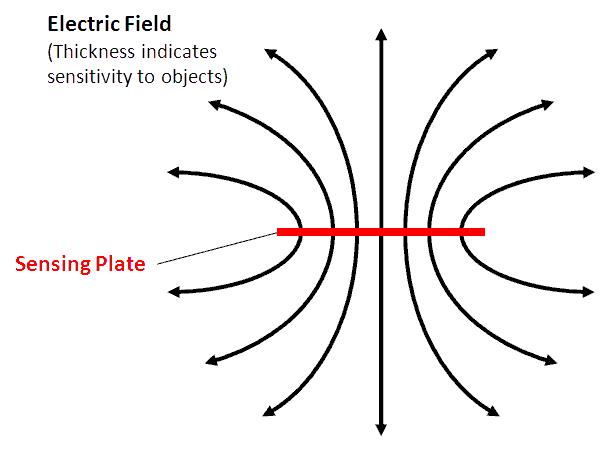
- Basic capacitive proximity sensor. It is sensitive to objects all around it.
|
Quite often, the capacitive proximity sensor has a ground plate on one side of the sensing plate to focus the sensitive region away from and shield the sensor from other circuitry and motion of the system. The drawback is that in order to get good shielding, the ground plate must be fairly close to the sensing plate, which increases base capacitance. Therefore, objects moving near the sensing plate create a much smaller percentage change in capacitance resulting in a less sensitive sensor.
|
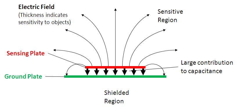
- A shielded capacitive proximity sensor. The sensitive region is reduced at the expense of decreased sensitivity (due to increased base capacitance).
|
A capaciflector uses a third, driven shielding plate between the sensing plate and ground. This driven shielding plate is electrically isolated from the shielding plate but is driven at the same potential. This serves to shield the sensing plate (as the ground plane did in the version above) but does not increase the base capacitance. Thus, smaller objects will produce a noticeable change in capacitance at larger distances.
|
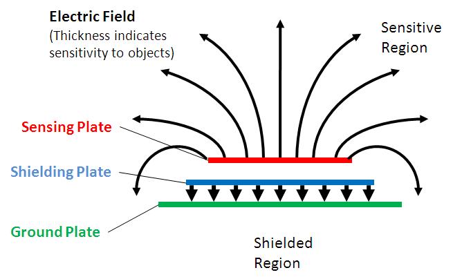
- The basic capaciflector concept. The increase in base capacitance is shifted to the shielding plate, while the sensing plate is still only sensitive on one side.
|
|
The Dual Mode Capaciflector seeks to use the shielding plate as a second, pressure sensor by sensing changes in capacitance between the shielding plate and ground. If a soft material is used to separate the shielding plate turned pressure sensing plate from the ground plate, applied force/pressure will cause the plates to come together, thus increasing the capacitance between them.
The pressure sensing plate still serves to shield the proximity sensing plate from everything below it (including circuitry and moving parts of the system). As an added bonus, the proximity sensing plate shields the pressure sensing plate from external objects; so the sensor have minimal crosstalk.
|
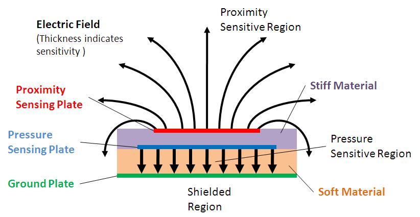
- Dual mode capaciflector in which a soft material allows pressure to change the capacitance of the shielding plate, now the pressure sensing plate.
|
Tri-Slope Conversion
|
One standard method of measuring capacitance of a single sided (or grounded) capacitor as is found in the capaciflector is dual-slope conversion. In dual-slope conversion, the sensing capacitor is used to pump charge onto a known storage capacitor which is connected in feedback in an op-amp circuit. This charge pumping is performed for a fixed time/number of cycles. The charge on the storage capacitor is then drained through a known resistance, and the drain time measured by looking at the output voltage of the op-amp. As the sensing cap's capacitance increases, more charge is transfered to the storage capacitor, and thus it takes longer to drain. More specifically; you determine the amount of charge stored on the storage capacitor by measuring the amount of time it takes to drain it, and then determine the amount of charge that must have been transferred per cycle when charging, which then allows you to calculate capacitance of the sensing cap.
|
Picture of dual slope
|
|
In a dual-slope conversion scheme the conversion accuracy is limited by timing accuracy. For a given timing accuracy, the relationship between the storage capacitor and sensing resistor controls both total conversion time and sensing accuracy. Unfortunately, time and accuracy are inversely proportional and more accurate conversions take increasingly more time (and larger sensing resistors and/or storage capacitors)
|
Capacitance and total time proportional equation
|
|
The first step changing from dual-slope to Tri-Slope conversion is to replace the sensing resistor with another switched capacitor. This third, drain capacitor pumps charge off of the storage capacitor in discrete amounts per cycle. By changing the switching speed and duty cycle, the amount of charge transfered per cycle (and therefore the effective drain current) can be controlled. Instead of timing how long it takes to drain the storage capacitor, you count the number of cycles it takes. From the number of drain cycles and the amount drained per cycle you can again calculate the amount of charge stored on the storage capacitor and from there the sensing cap's capacitance (as in the dual-slope method).
|
Picture of tri-slope (actually dual slope with switched capacitance draining)
|
|
While conversion accuracy was limited by timing accuracy in the dual-slope method, conversion accuracy is limited by the amount of charge drained per cycle in the tri-slope method. If that amount is large, it is possible to over-drain the storage capacitor by a large amount and the conversion will not be very accurate. However, if very small amounts of charge are drained per cycle, the storage capacitor will not be over-drained and the conversion can be very accurate.
|
Compare accuracy for large and small steps
|
|
The third slope in the Tri-Slope conversion is created by splitting the draining stage into two sections; a fast drain and a slow drain. The fast drain section pumps large amounts of charge off of the storage capacitor per cycle. If the conversion were to finish during this stage, the result would be a fast but very inaccurate conversion. Thus, as the storage capacitor gets close to being fully drained, the drain capacitor switches into slow drain mode and begins to move small amounts of charge off of the storage capacitor each cycle. This section of the conversion takes longer, but is more accurate.
When a conversion finishes, the total charge drained is calculated from the number of fast and slow drain cycles. This again allows for the amount of charge per charging cycle to be computed and from that the capacitance of the sensing capacitor.
|
Picture of full tri-slope
|
Technology Details
Most of the detailed work has gone into circuit design for the Tri-Slope conversion and working out how to calculate charge transfer and therefore measured capacitance from numbers of charging or drain cycles. Additionally, creating a dual-mode capaciflector node will introduce a large (or at least non-insignificant) capacitance between the two sensing plates which needs to be accounted for.
Switched Capacitor Charge Transfer
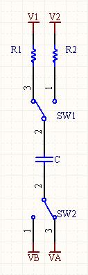
The most general version of a switched capacitor is shown to the right. The two leads of the capacitor are switched from V1 and VA to V2 and VB; these two configuration are called state 1 and state 2 respectively. The following quantities will be used in formulas below:
| Identifier |
Quantity |
| V1 |
Voltage source attached to side X of capacitor during state 1 |
| V2 |
Voltage source attached to side X of capacitor during state 2 |
| VA |
Voltage source attached to side Y of capacitor during state 1 |
| VB |
Voltage source attached to side Y of capacitor during state 2 |
| C |
value of switched capacitor |
| R1 |
series resistance in state 1 |
| R2 |
series resistance in state 2 |
| t1 |
time spent in state 1 |
| t2 |
time spent in state 2 |
|
|
If we assume steady state, meaning the charge on the capacitor when switched from state 1 to state 2 and vice versa is the same every cycle, then we can calculate the amount of charge sourced/sinked by each voltage source, as well as the effective or average current sourced/sinked and the maximum instantaneous current sourced/sinked. If we let


then we find that
| |
Charge Sourced |
Average Current Sourced |
Maximum Current Sourced |
| V1 |
Q |
I |
I_max1 |
| V2 |
-Q |
-I |
I_max2 |
| VA |
-Q |
-I |
-I_max1 |
| VB |
Q |
I |
-I_max2 |
Stray Capacitance Sensitivity
We needed to investigate how stray capacitance could affect the charge transfered in various stages of the conversion. Because those stray capacitances will be unknown (and likely changing) we would like to eliminate their effect if possible.
|
To that end a general switched capacitor with stray capacitances was analyzed (circuit to the right). The effect of stray capacitance is summarized in the table below.
|
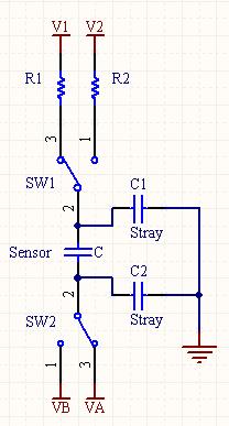
|
If we assume that node V1 is the node draining charge from the storage cap, then we see that setting V1 and V1 to the same value will eliminate the effect of stray capacitance on the amount of charge drained from the storage cap per cycle.
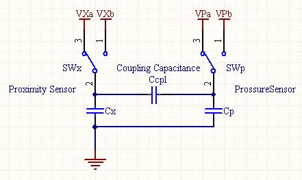
Proximity and Pressure Coupling
THIS SECTION NEEDS WORK
|
The tri-slope conversion technique relies on accurately determining the amount of charge transfered on/off of various capacitors. The benefit of the shielding plate in a capaciflector is that it shields without increasing the base capacitance; that is a direct result of the shielding plate and sensing plate being at the same potential. When we physically build a dual-mode capaciflector cell we will introduce a non-negligible coupling capacitance between the two sensing plates as indicated to the right. We need to determine the effect this will have on the working of the circuit.
The closed form solution for this particular configuration is complicated and not particularly helpful. However, we can simulate with various configurations of R's and C's to determine what properties we might want. Some sample simulations of the voltage on each sensing plate are shown below.
|
|
Pictures of simulations
The simulation gives us a few insights. To begin with, we will have the best luck keeping the two sensing plates at the same voltage if we switch the two sensing plates at the same time. This way both are charging/discharging in sync.
Secondly, as C_cpl approaches 0, the circuits operate more independently. This means that the voltage on the two plates is only a function of the sensing capacitance and the series resistance. We could pick the series resistance such that plates charge in unison (RxCx = RpCp), keeping the plates at the same potential, but as soon as one of the capacitances changes the two plates will charge at different rates and
On the other hand, if we increase C_cpl,
Current Implementation
One prototype (breadboard) version of a single cell dual-mode capaciflector has been built. In order to interface with multiple cells, analog multiplexers need to be added to connect to the sensing plates of the different cells. This will require additional digital output lines on the microcontroller.
Hardware
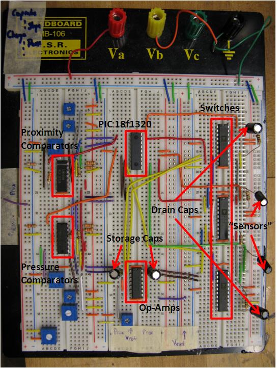
- First prototype circuit for the Dual Mode Capaciflector
The circuitry is implemented using a PIC18f1320 microcontroller. This PIC is sufficient for a single cell, but does not have any extra output pins for adding multiplexers (in the simplest configuration; see
Notes for ways to reduce pins). The comparators used are LM339s. The switches are
ADG333A? quad-SPDT analog switches. These were chosen for their low charge injection. Again, because the circuit relies on accurately accounting for charge transfer, any charge introduced due to the switches turning on/off will either need to be accounted for (more work in software) or introduce error to the conversion. The complete circuit diagram is below and found
here.
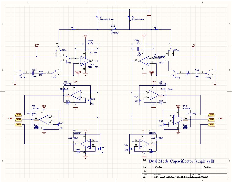
There are two tri-slope converters, one for proximity sensing and one for pressure. Each tri-slope converter has 5 switches (two which are linked,
SW3A? and
SW3B? ) to control charge transfer. SW1 controls charging and discharging the sensing plate, SW2 changes from charging mode to drain mode, SW3 controls the draining of the storage capacitor, and SW4 is used to exactly discharge the storage capacitor (to account for over-draining).
The PIC has 6 output lines dedicated to controlling the switches. One line controls both
SW1X? and
SW1P? so that the sensing plates are charged in unison.
SW2X? and
SW2P? are also controlled together so that when one storage cap is fully charged both sensors begin draining their storage caps. The 4 remaining lines control
SW3AX? and
SW3BX? ,
SW3AP? and
SW3BP? ,
SW4X? , and
SW4P? . This allows the two tri-slope conversion circuits to discharge their storage caps at different rates and allows them to finish conversions at different times. The outputs for a typical switching sequence are shown below, with the states indicated for each converter.
There are 6 comparators (with hysteresis) used to indicate when each converter has reached 3 important states; fully charged storage capacitor (start fast drain), mostly drained storage capacitor (switch from fast to slow drain), and storage capacitor fully drained (conversion done). The op-amp voltage output from each converter is used as the inverting input for 3 of the comparators. The output of these 6 comparators are used as digital input signals to the PIC to control transitions between different modes.
All signals for a complete conversion are shown below including modes for each of the two converters.
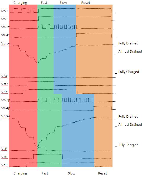
- In this example, the pressure circuit finished fully charging before the proximity circuit.
Software
The software is written in C. Two interrupt-driven timers are used to control the switches for each tri-slope converter. The timer which controls the proximity sensor also controls the pressure sensor during charging of the storage capacitor. In addition, simple interrupt-driven serial communication transmits the latest conversion results continuously. Source code can be found here. %x%
ADD LINK
Communication
The communication code is located in
serial.h and
serial.c Right now the serial communication is extremely simple. The serial line is 9600 baud, 8 data bits, no parity, 1 stop bit, and no flow control. The PIC does not accept commands. It continually transmits the latest conversion results in the following 7-byte packet:
| Byte # |
Description |
| 0 |
Start - 0x00 The data bytes will always be non-zero |
| 1 |
Prox Charge Count - Number of charging cycles for the prox circuit (equal to byte 4) |
| 2 |
Prox Fast Count - Number of fast drain cycles for the prox circuit |
| 3 |
Prox Slow Count - Number of slow drain cycles for the prox circuit |
| 4 |
Pres Charge Count - Number of charging cycles for the pres circuit (equal to byte 1) |
| 5 |
Pres Fast Count - Number of fast drain cycles for the pres circuit |
| 6 |
Pres Slow Count - Number of slow drain cycles for the pres circuit |
All calculation is for the moment off loaded to wherever the PIC sends the data.
Switching
The code for control of the tri-slope conversion is located in
sensing.h and
sensing.c. The switching is controlled based on timer overflow interrupts, which have been given high priority. Nothing else (including the serial communications) should be given high priority since the switching times are critical and need to be able to interrupt anything else.
For clarity, each step in the conversion process has been given a name in the code, which are explained here.
| Step |
Description |
| CHARGING |
SW1 connects the sensing plate to V+ and it is charging |
| DISCHARGING |
SW1 and SW2 connect the sensing plate to the op-amp. Charge is moving from sensing plate to storage cap. |
| FAST_SIPHON |
SW2 and SW3s connect the drain cap to the op-amp and to ground. A large amount of charge is moving from storage cap to drain cap. |
| FAST_DRAIN |
SW3s connect the drain cap to V_ref and V+ and charge moves off of the drain cap. |
| SLOW_SIPHON |
SW2 and SW3s connect the drain cap to the op-amp and to ground. A small amount of charge is moving from storage cap to drain cap. |
| SLOW_DRAIN |
SW3s connect the drain cap to V_ref and V+ and charge moves off of the drain cap. |
| RESETTING |
SW4 connects to remove any charge on either side of the storage cap, resetting for the next conversion. |
| DONE |
SW4 has been connected long enough to reset the storage cap. The next conversion can begin. |
The interrupt for timer 0 (charging/discharging for both, all control for proximity) looks roughly like:
- Timer 0 overflows -> Check current timer 0 mode
- CHARGING -> Change mode to DISCHARGING, flip switches, reset timer value.
- DISCHARGING -> increment the charge count
- If either storage cap is full -> Change both timer modes to FAST_SIPHON, flip switches, reset both timers' values.
- Otherwise -> Change mode to CHARGING, flip switches, reset timer value.
- FAST_SIPHON -> Change mode to FAST_DRAIN, flip switches, reset timer value.
- FAST_DRAIN -> increment proximity fast drain count.
- If prox storage cap is almost drained -> Change timer mode to SLOW_SIPHON, flip switches, reset timer value.
- Otherwise -> Change mode to FAST_SIPHON, flip switches, reset timer value.
- SLOW_SIPHON -> Change mode to SLOW_DRAIN, flip switches, reset timer value.
- SLOW_DRAIN -> increment proximity slow drain count.
- If prox storage cap is fully drained -> change timer mode to RESETTING, flip switches, reset timer value.
- Otherwise -> Change mode to SLOW_SIPHON, flip switches, reset timer value.
- RESETTING
- If pressure circuit is DONE (timer 1) -> send conversion data over serial, change mode to CHARGING, flip switches, reset timer value.
- Otherwise -> change mode to DONE, disable timer 0 interrupts.
The interrupt for timer 1 (draining and resetting control for pressure circuit) looks like:
- Timer 1 overflows -> Check current timer 1 mode
- FAST_SIPHON -> Change mode to FAST_DRAIN, flip switches, reset timer value.
- FAST_DRAIN -> increment proximity fast drain count.
- If pres storage cap is almost drained -> Change timer mode to SLOW_SIPHON, flip switches, reset timer value.
- Otherwise -> Change mode to FAST_SIPHON, flip switches, reset timer value.
- SLOW_SIPHON -> Change mode to SLOW_DRAIN, flip switches, reset timer value.
- SLOW_DRAIN -> increment proximity slow drain count.
- If pres storage cap is fully drained -> change timer mode to RESETTING, flip switches, reset timer value.
- Otherwise -> Change mode to SLOW_SIPHON, flip switches, reset timer value.
- RESETTING -> disable timer 1 interrupts.
- If prox circuit (timer 0) is DONE -> send conversion data, change timer 0 mode to Charging, flip switches, reset timer 0 value, enable timer 0 interrupts.
- Otherwise -> change mode to DONE
Notes for Future Work
- SW4 does not need to be a "good" analog switch with very low charge injection.
- To save pins, SW4X? and SW4P? could be linked, since after one conversion is done that capacitor does not need to be reset immediately; it could wait until right before the next conversion is ready to start.
- A single input pin could be saved by creating a window comparator out of the two "storage cap charged" comparators.
- Ideally, a microcontroller with two built-in comparators and two independent, internally controlled references could be used to eliminate the external comparators and reduce the number of input lines from 6 to 2.
- When multiplexing is added we will require N additional output lines to sample from 2^N cells.
- Multiplexing for the proximity sensor could be handled differently to create some interesting effects, though the implementation hasn't yet been worked out.
- If all the proximity plates were used at the same time (and all shielded correctly) the range/sensitivity for proximity could be drastically increased.
- A sensing scheme could be: sense with all proximity plates linked until something gets close enough. Then switch to 4 subgroups of sensing plates to see which quadrant the object is in. Continue further divisions to refine location as the object gets closer, until finally each sensing plate is operating individually.
- Speed - for the sensing capacitances I expect (~100s of pF) a single conversion can take as little as 1ms. However that requires switching speeds of ~1GHz or higher.
- We could get a much faster processor (most PICs max out at 40MHz).
- We could use a PWM channel to control switches and count the number of pulses in code. This would require at least 2 PWM channels (one per conversion circuit), though 4 would be better, and 2 counter inputs (again 4 would be better).
- We would also need to find analog switches which can handle those frequencies; I don't think the ADG333A? can
- The first step in adding comm functionality would be to send commands from PC to PIC to change the times spent in all the switch configurations. This would allow us to easily modify the behavior as we change capacitances.
 HSPrivate Web>HumanSafeRobot > SkinDesign>DualModeCapaciflector (07 Aug 2008, BarrettHeyneman)


