SummerBlogs August 20th
August 17th
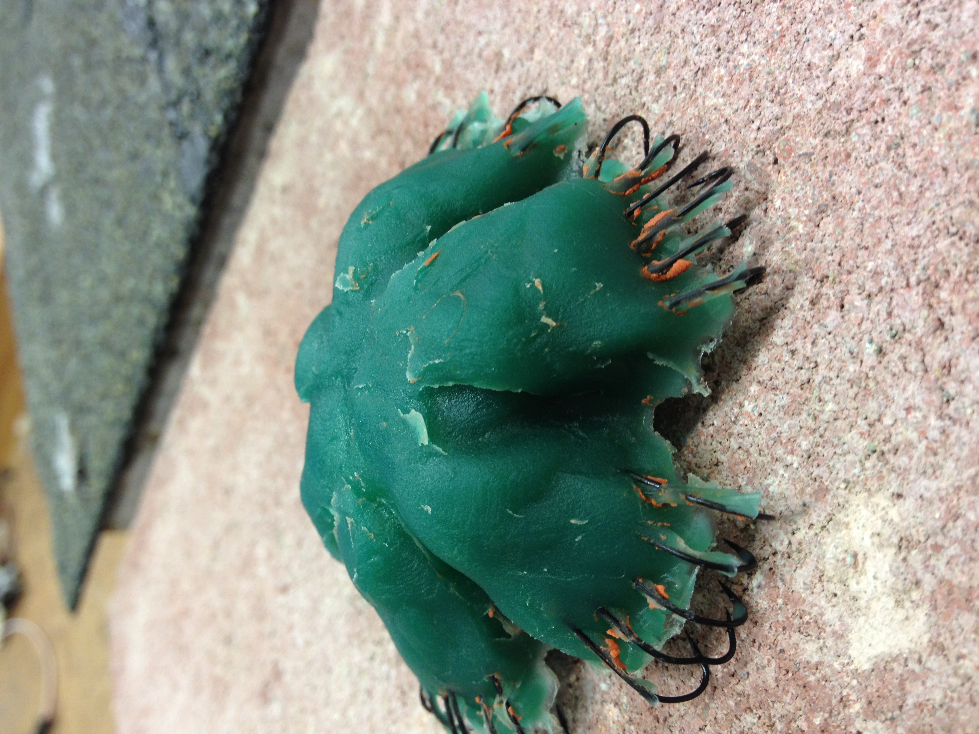
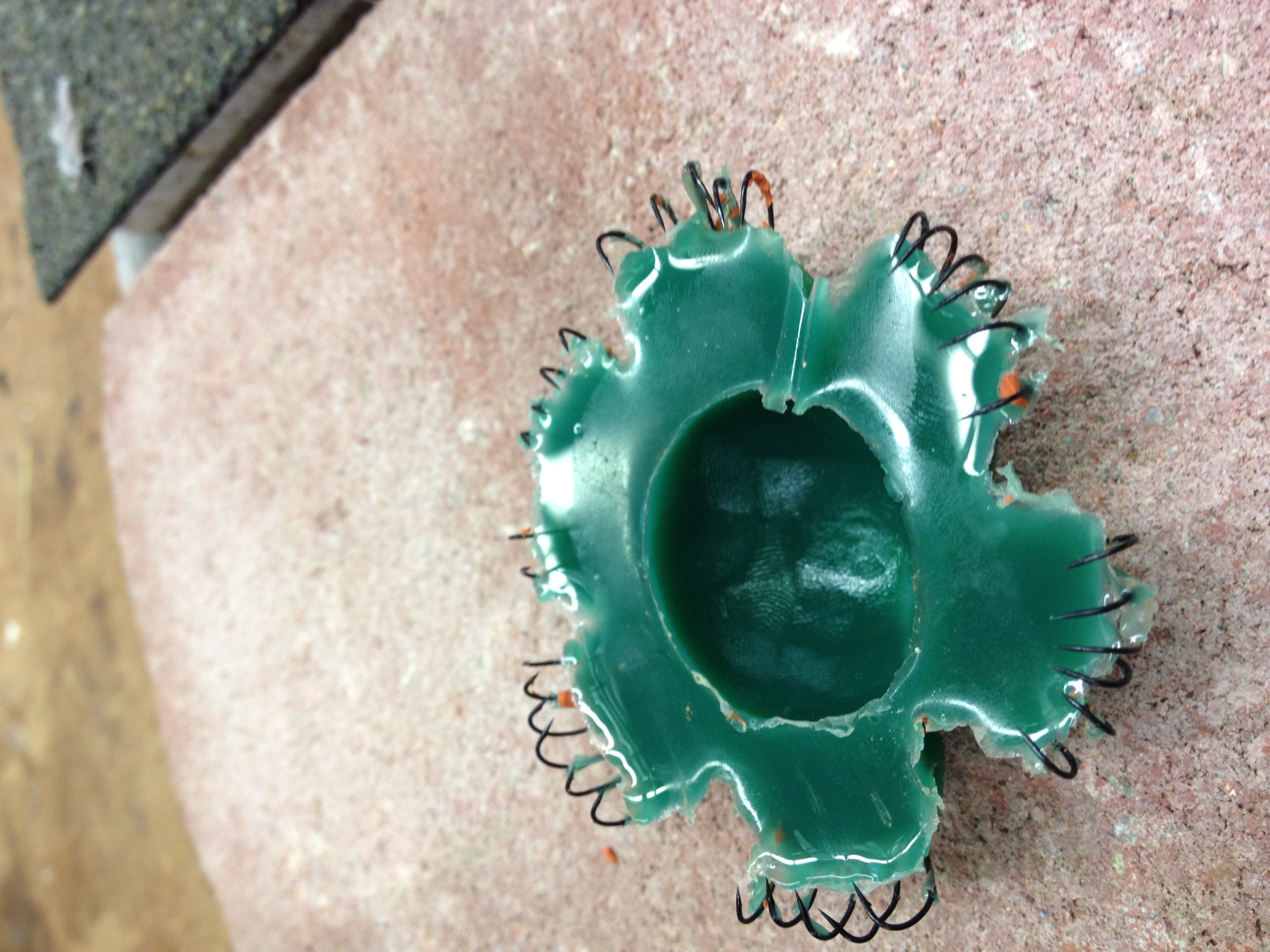
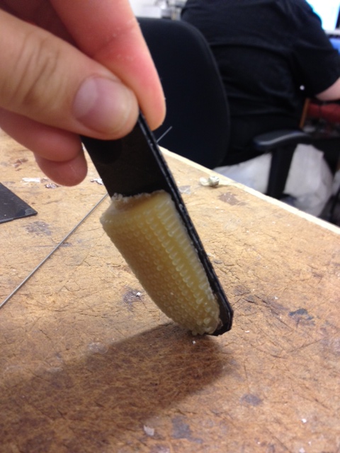
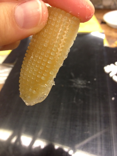
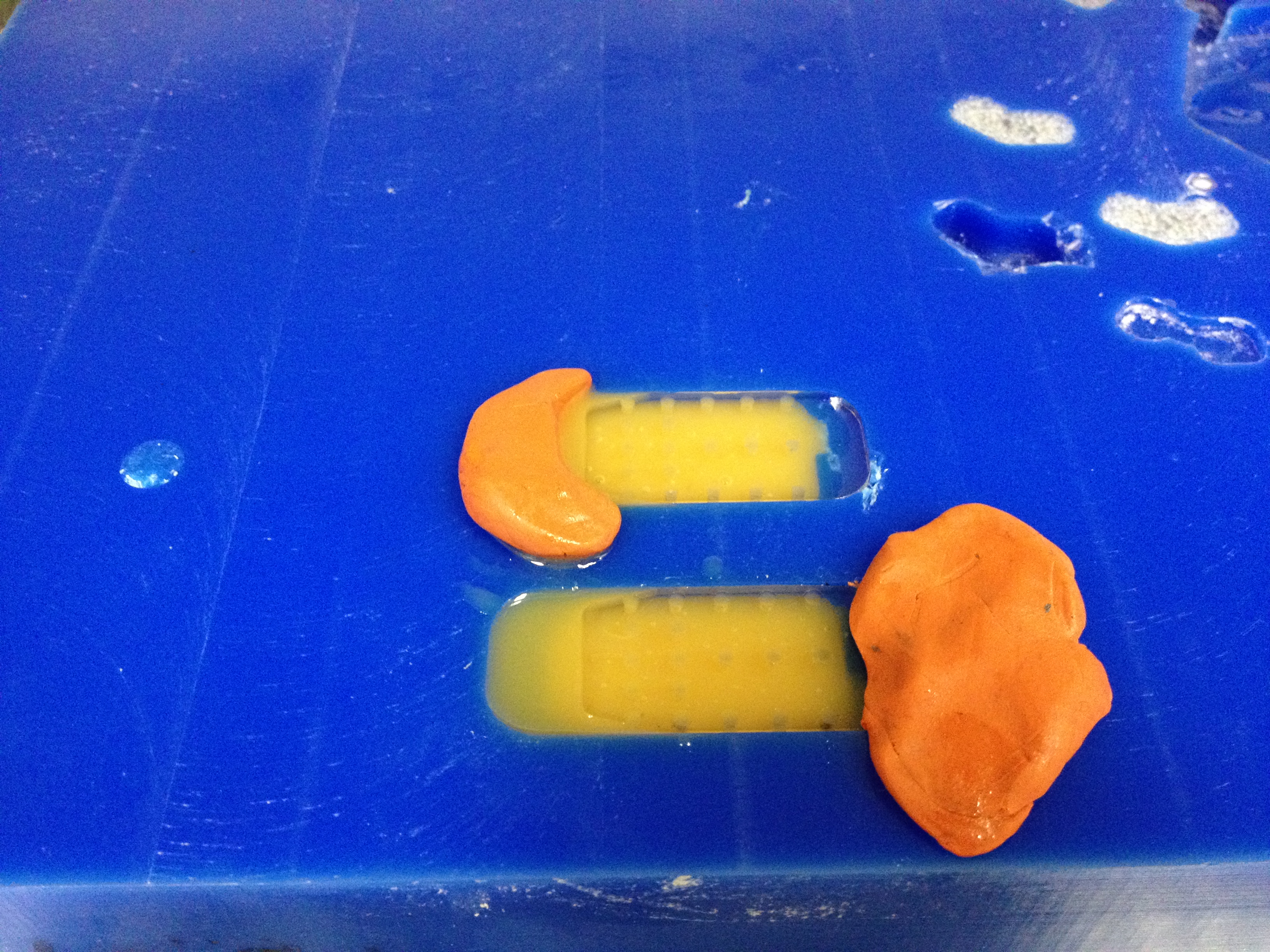
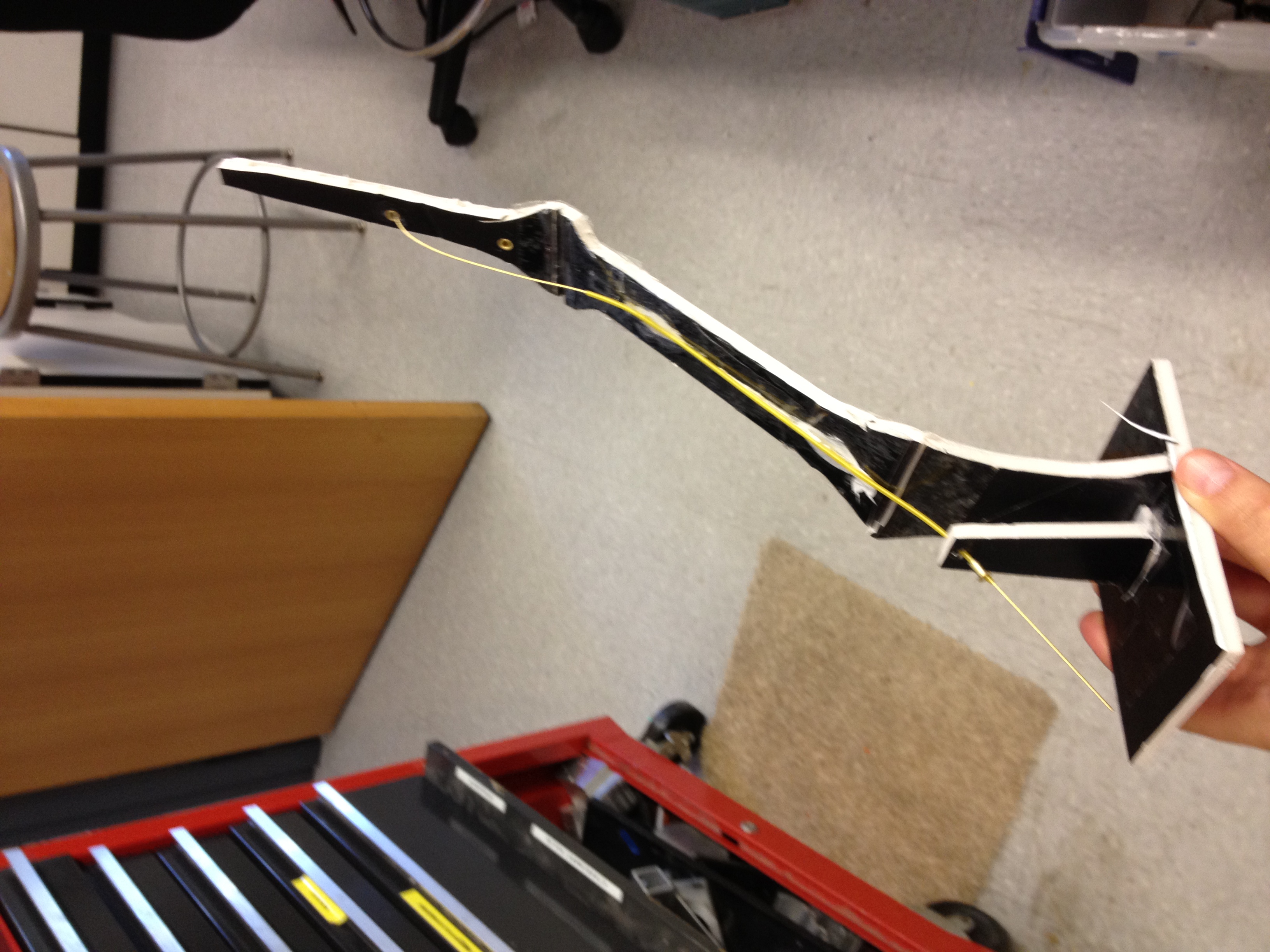
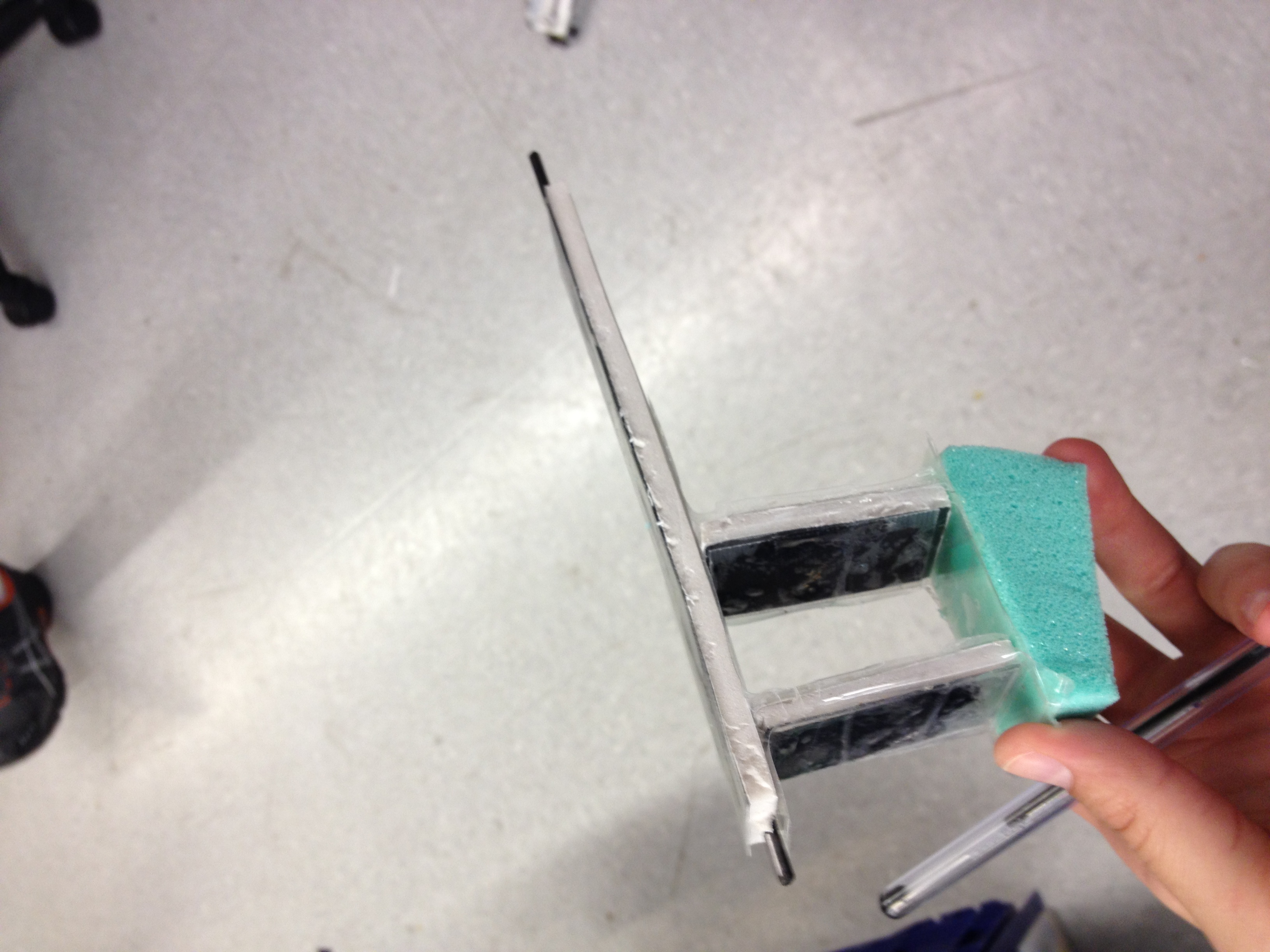
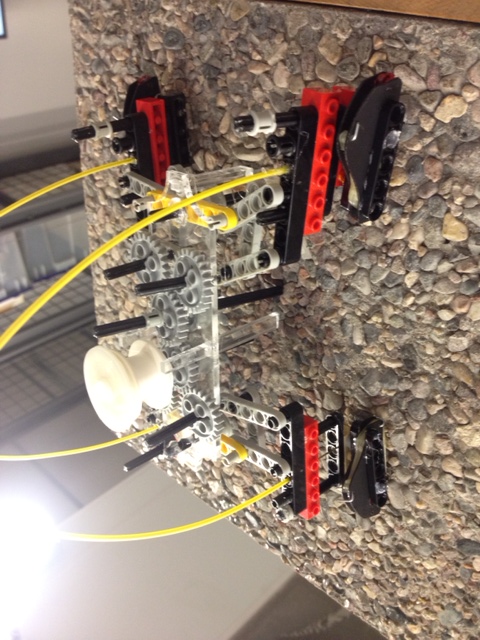
My squishy is released from the mold and it works. Surprisingly sticks to a cinderblock with little effort.
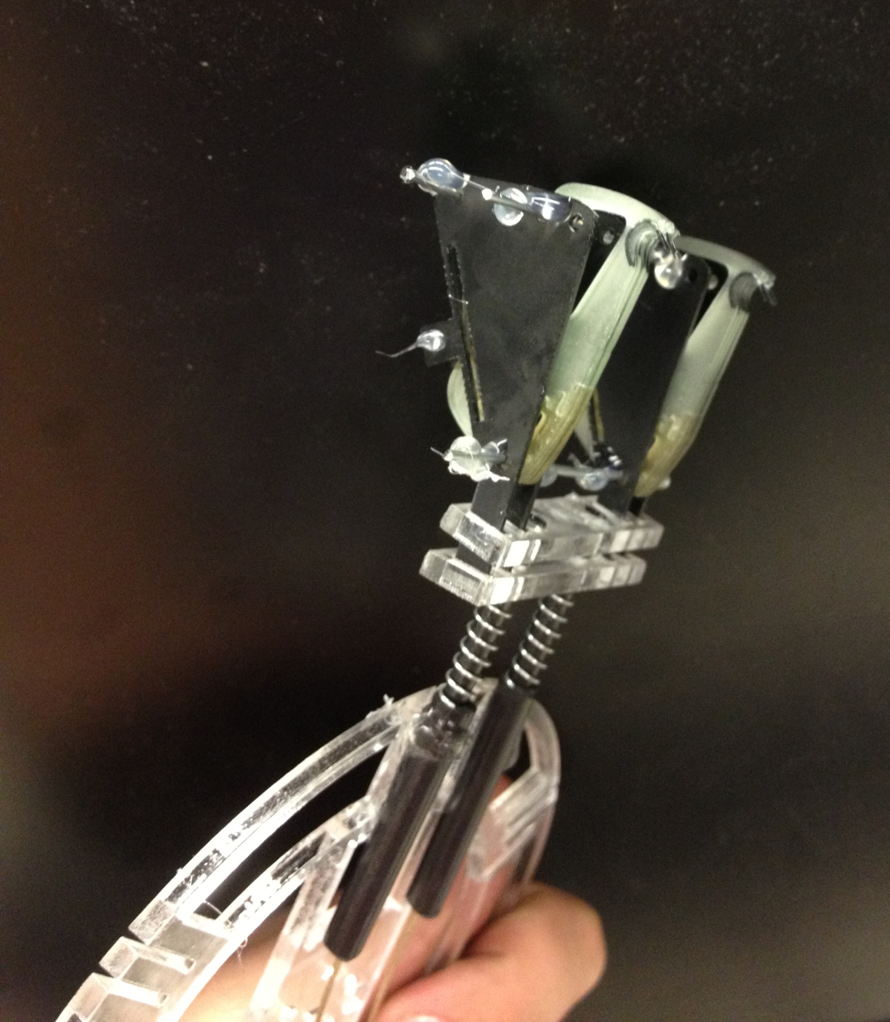
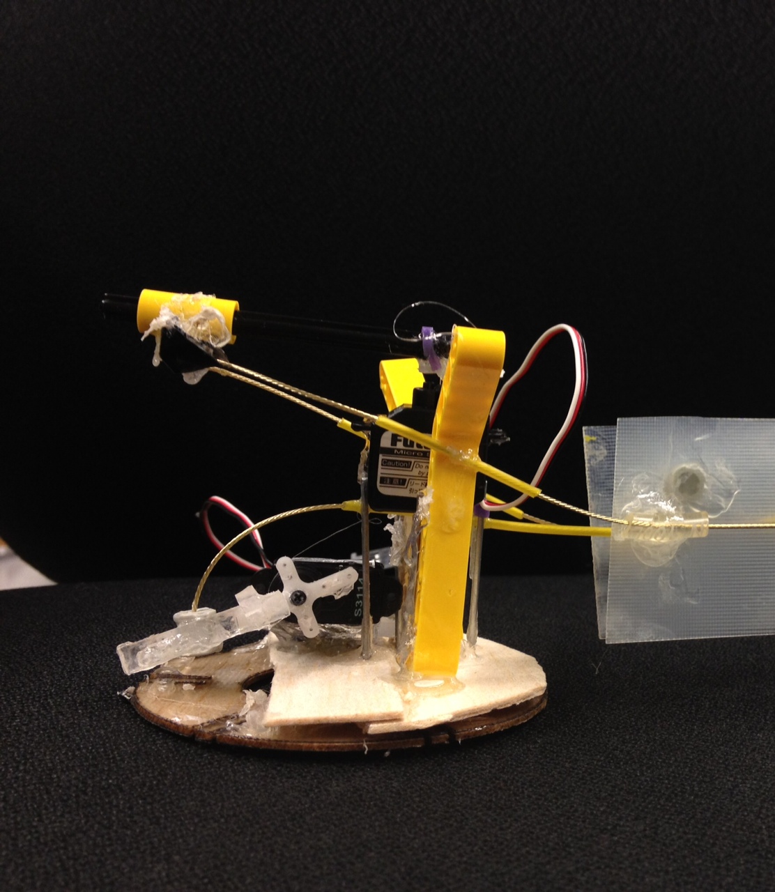
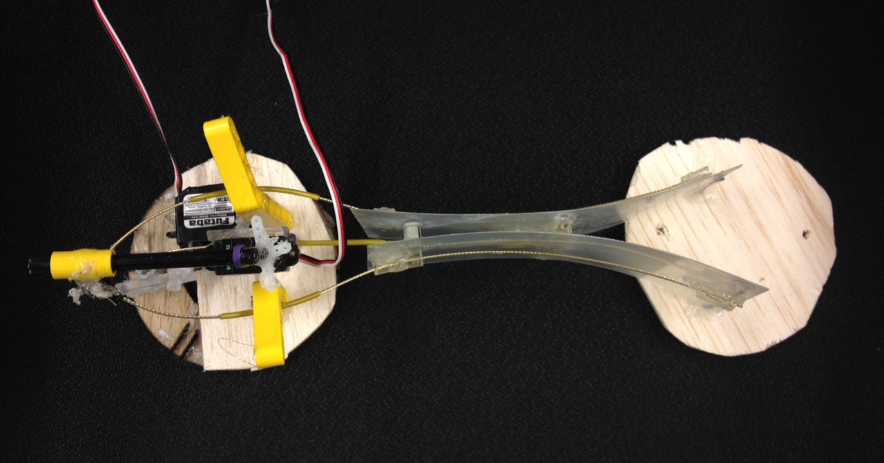
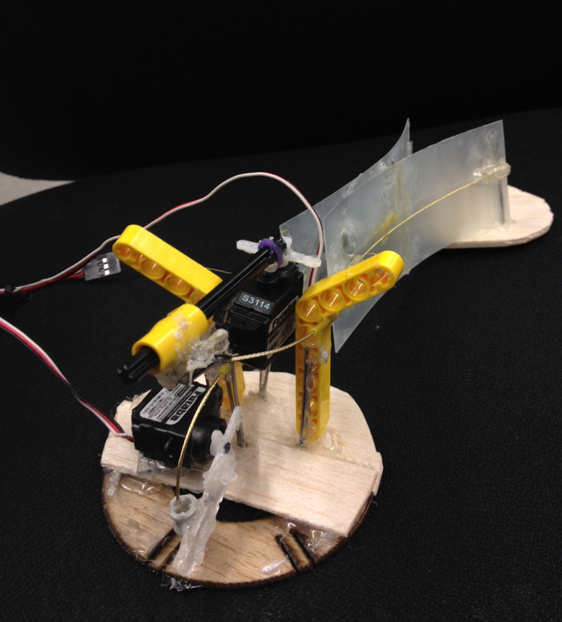
Assembly of the latest design.
August 16th
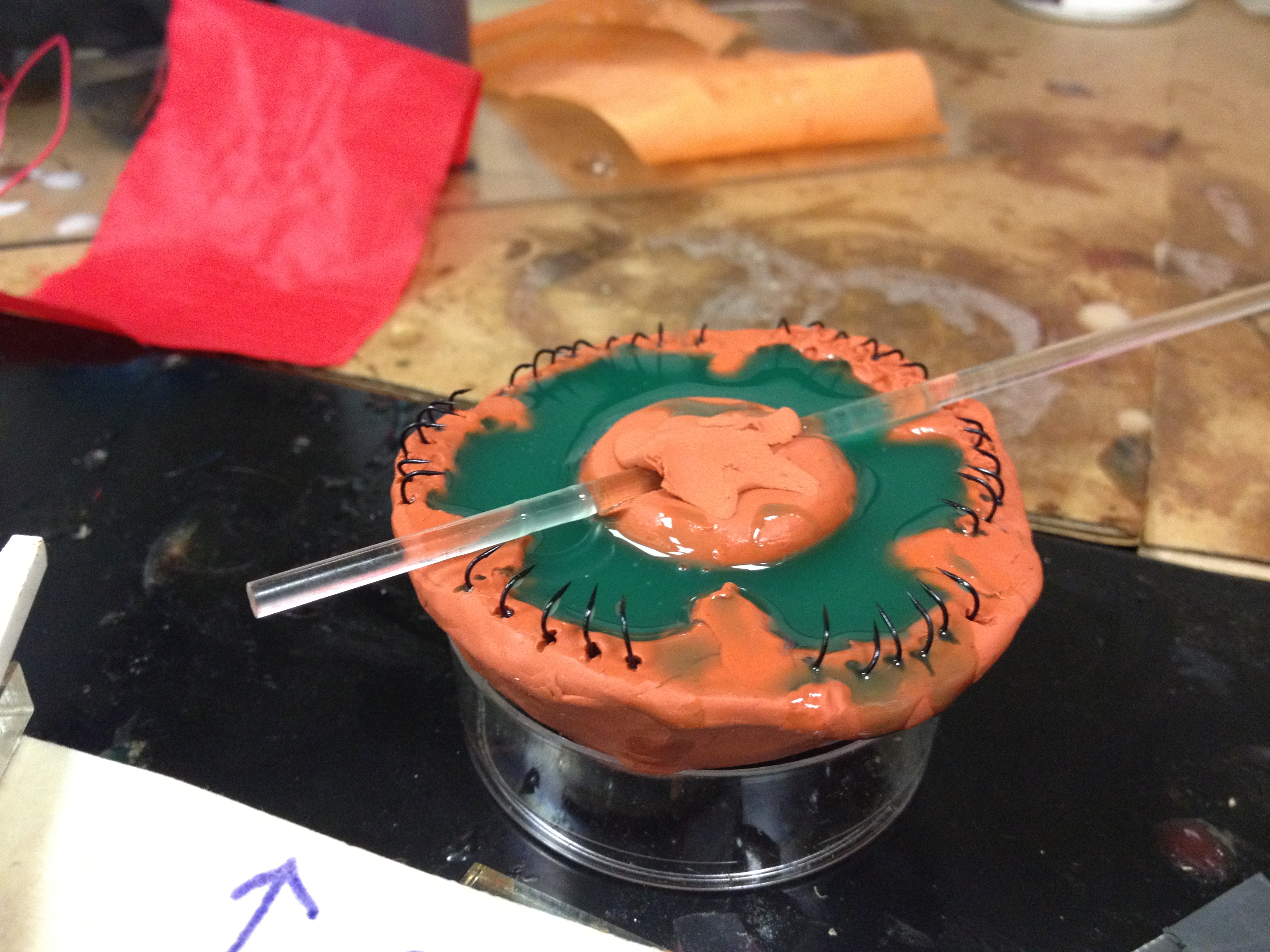
Meanwhile...I couldn't control my urge to make something squishy, so I made a mold out of modeling clay. So fun!
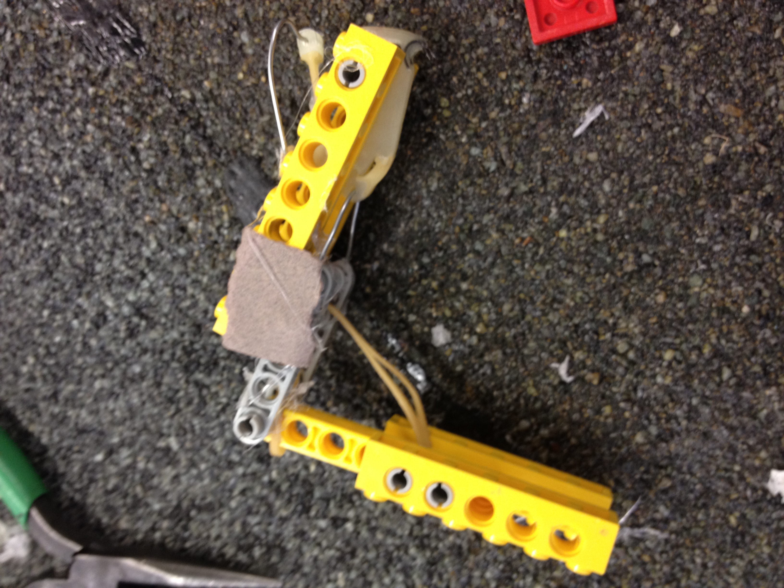
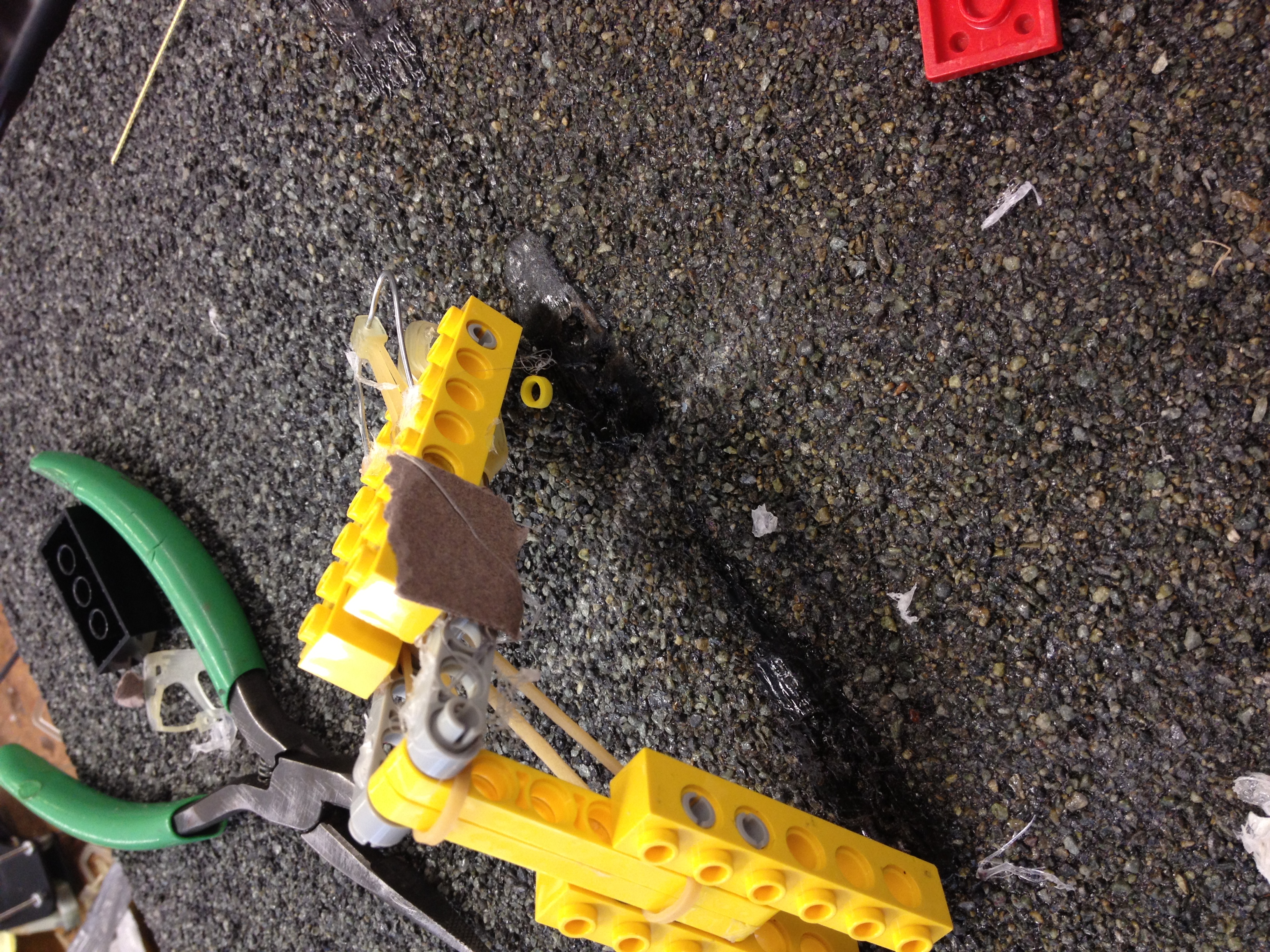
We went back to the drawing board and redesigned the feet--the force on the foot needed to be horizonal.
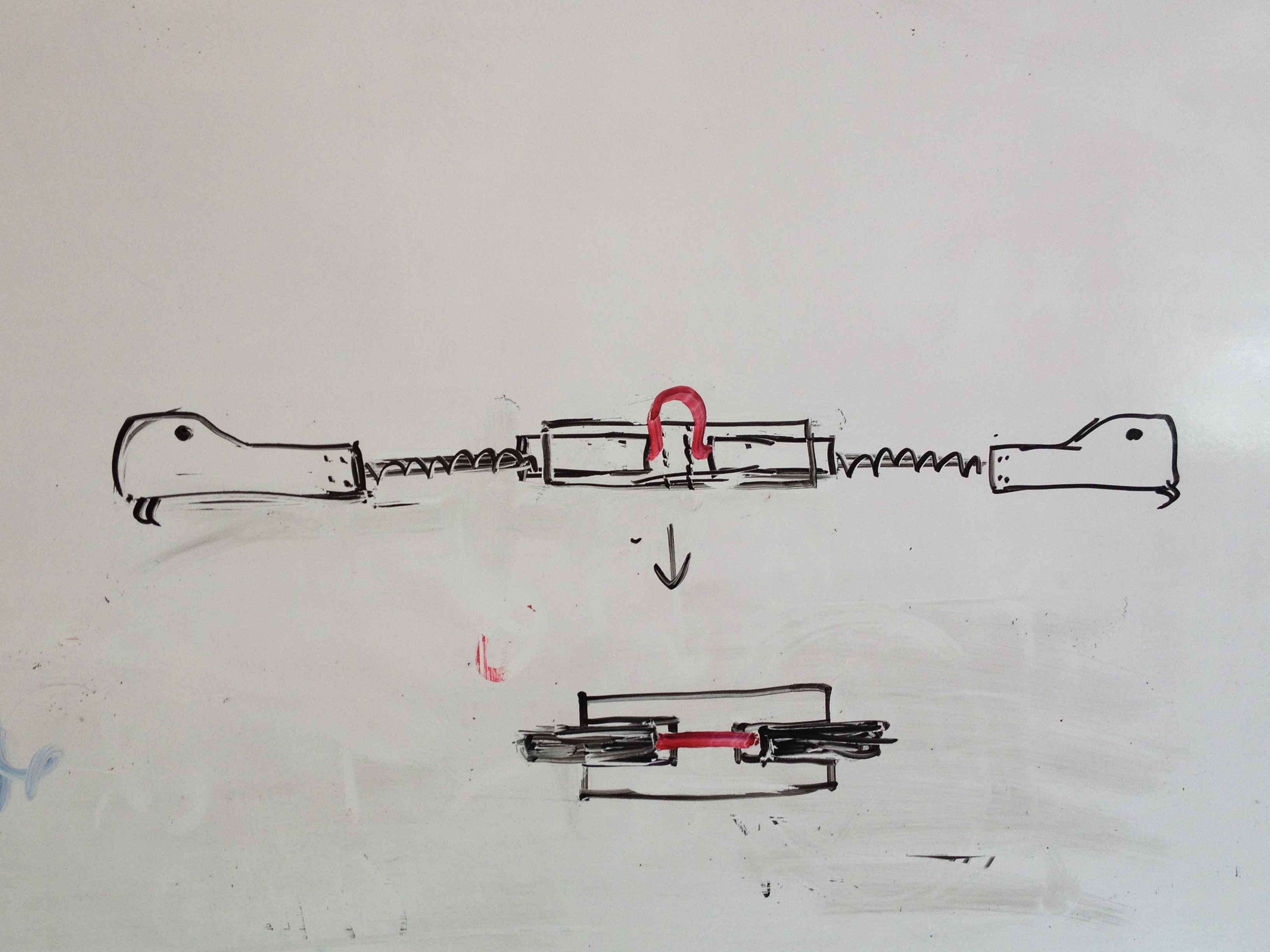
The feet in our previous designs "stuck" with the help of rotational motion (so there's a vertical force component at the end).
August 15th
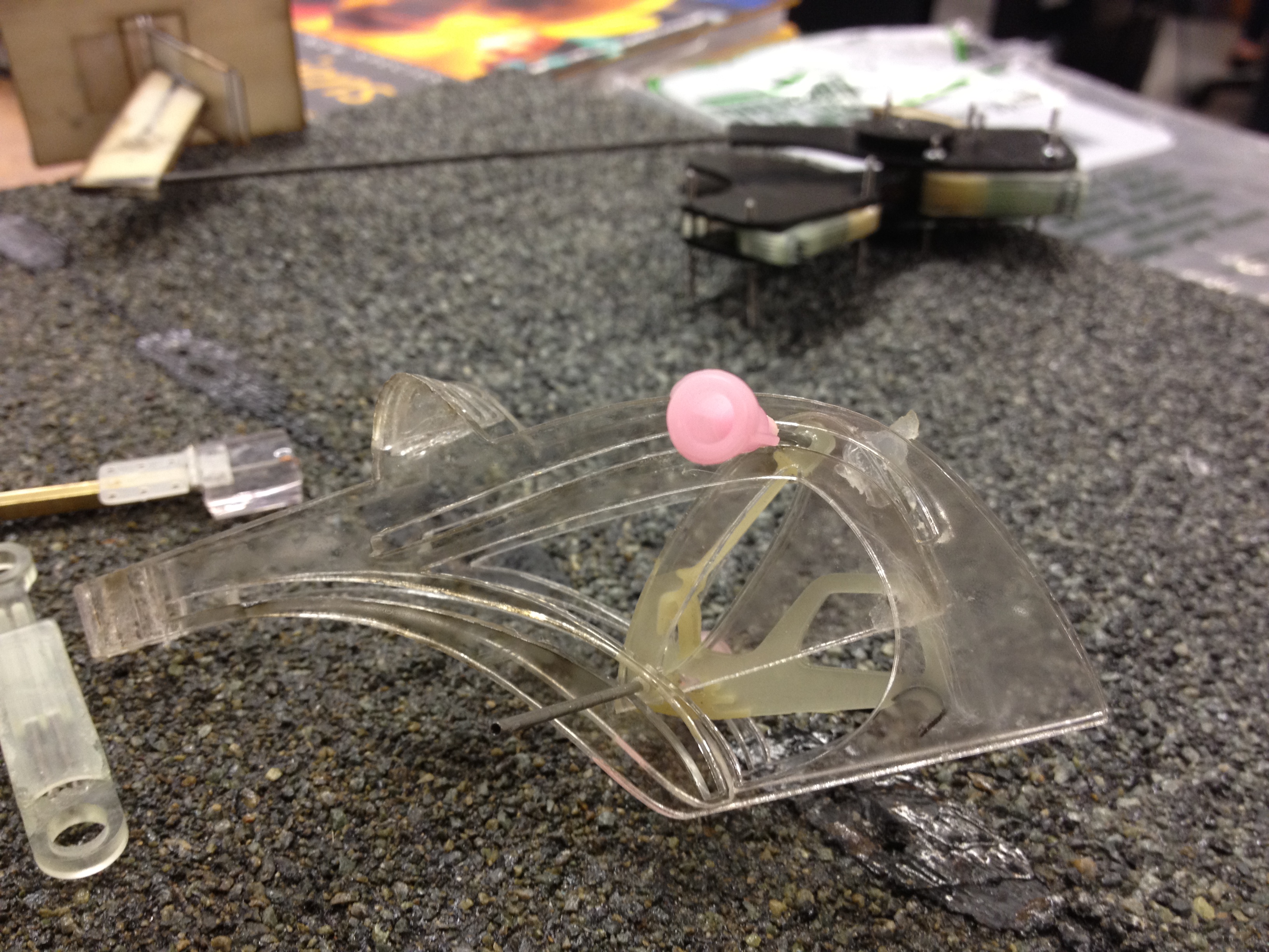
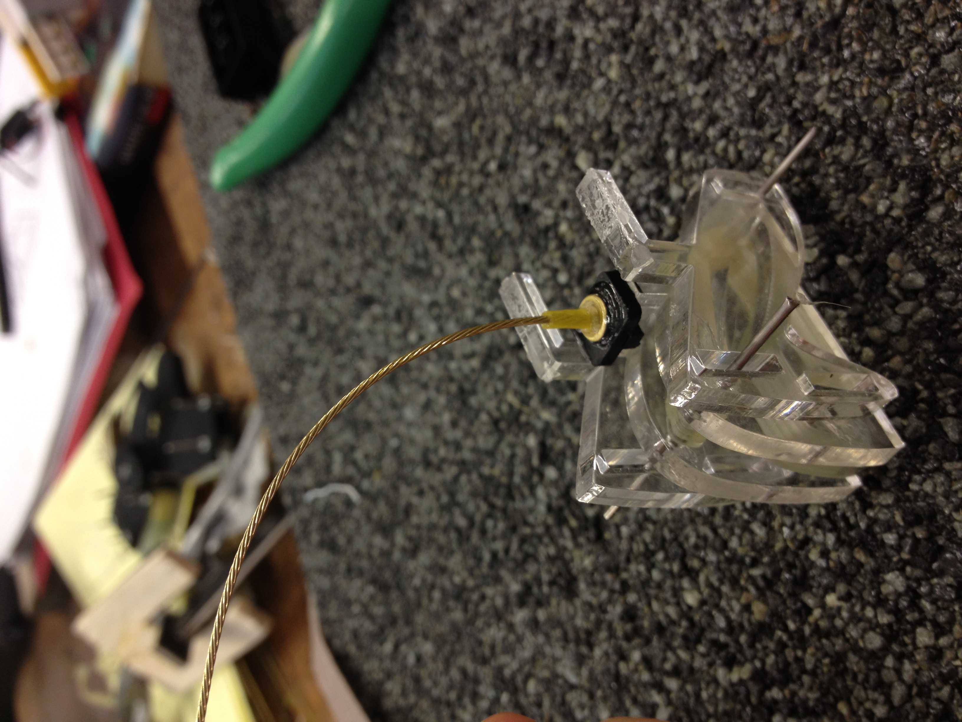
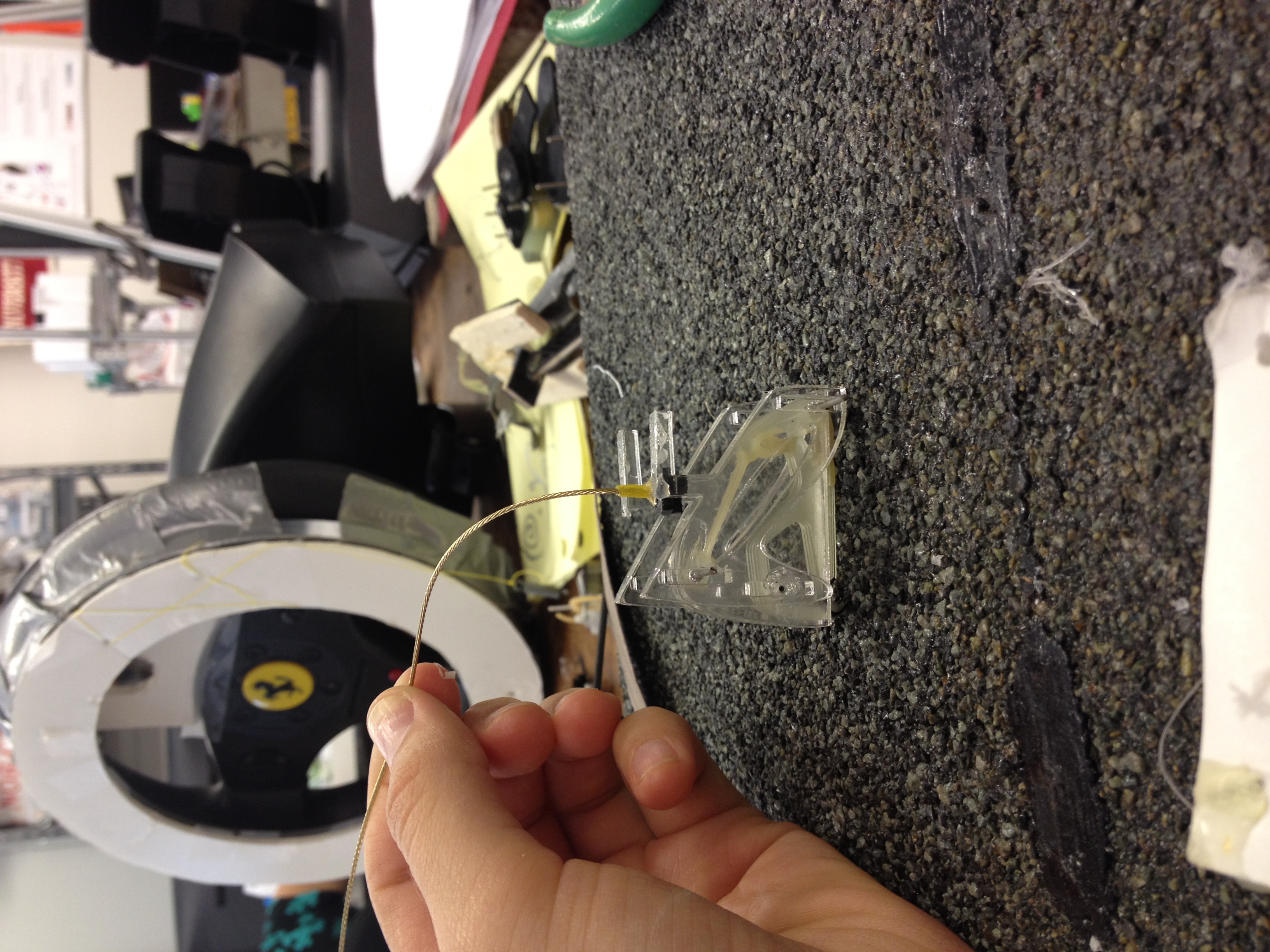
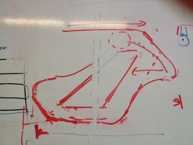
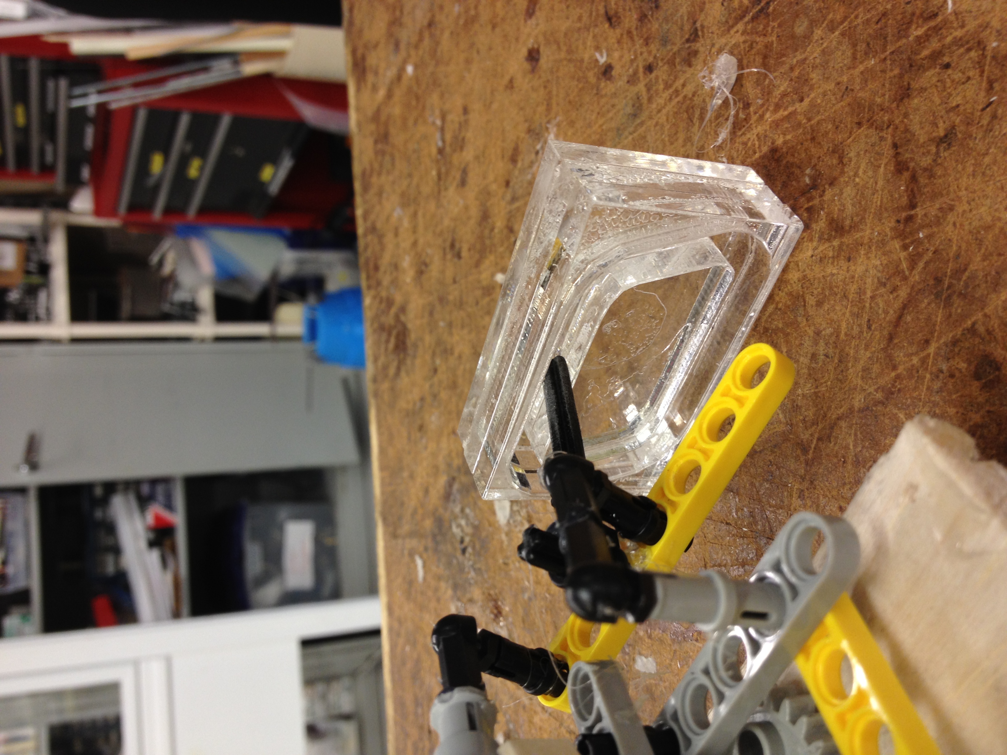
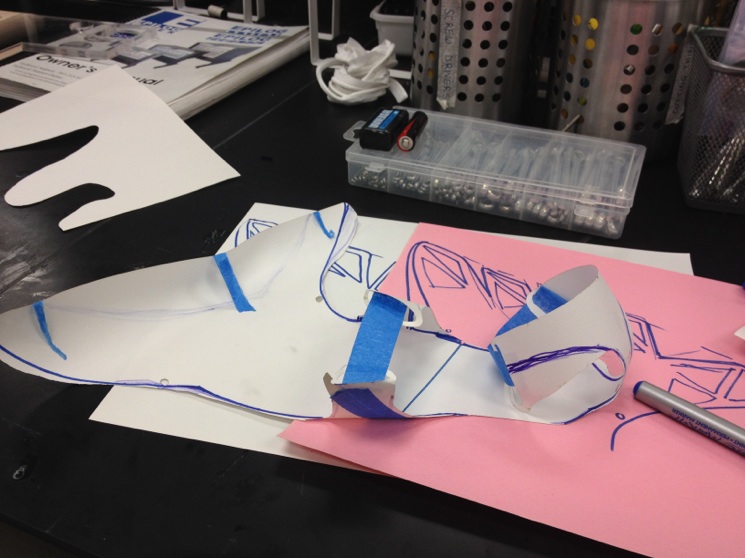
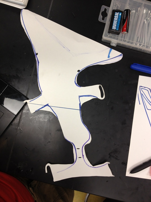
Mark helped Forest and me figure out the ideal trajectory for the toe (around a cm of nearly-horizonal travel). To do this we chose various points and rotated the hook on a piece of transparency film.
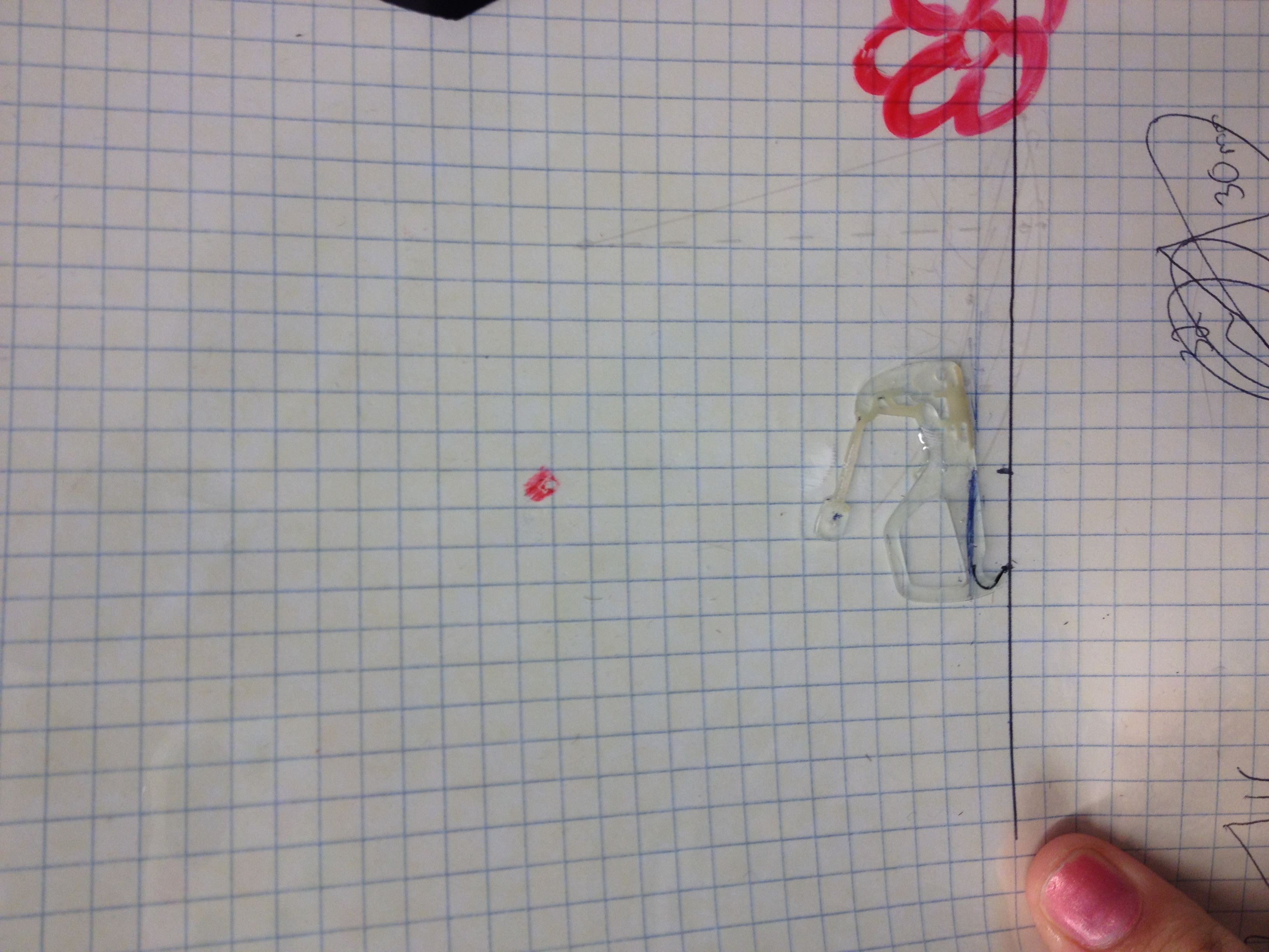
The ideal rotation point was relatively far away from the "ground," and so our new foot design sports an extension
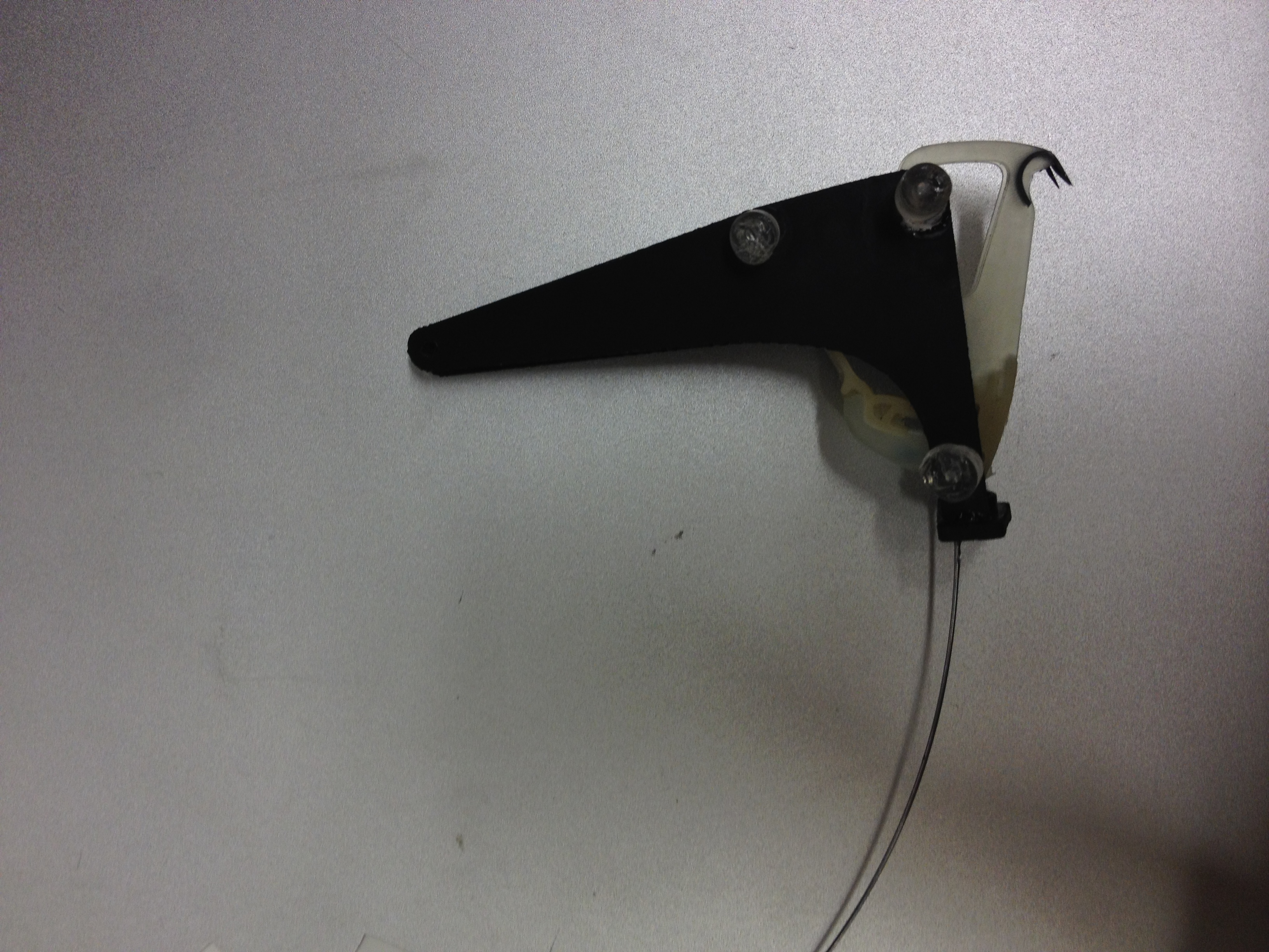
Once again, the gripping was less than great. We tried to change the point of rotation (you can see the wire) once again, but that didn't help too much.
August 14th
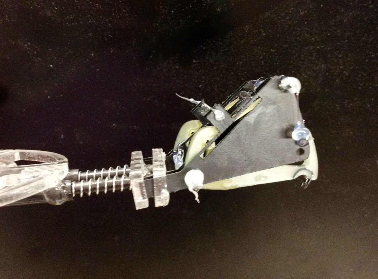
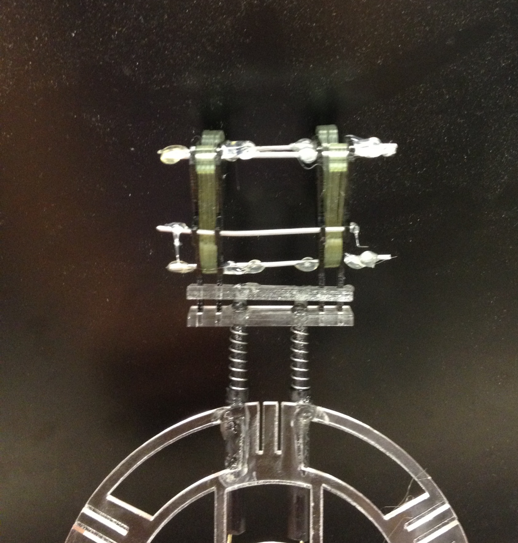
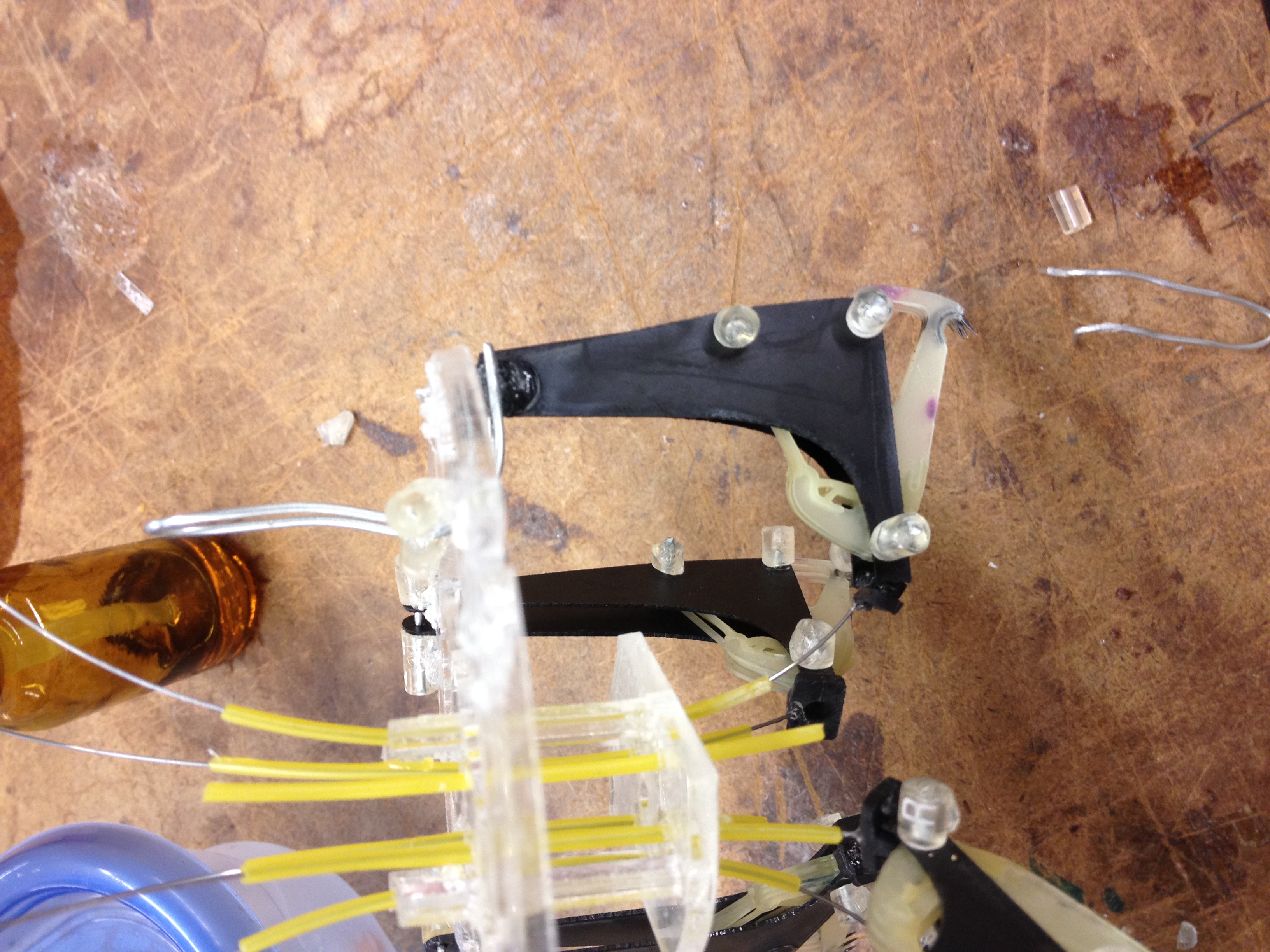
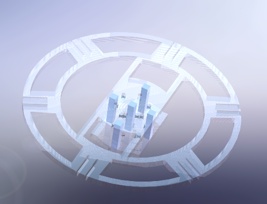
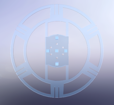
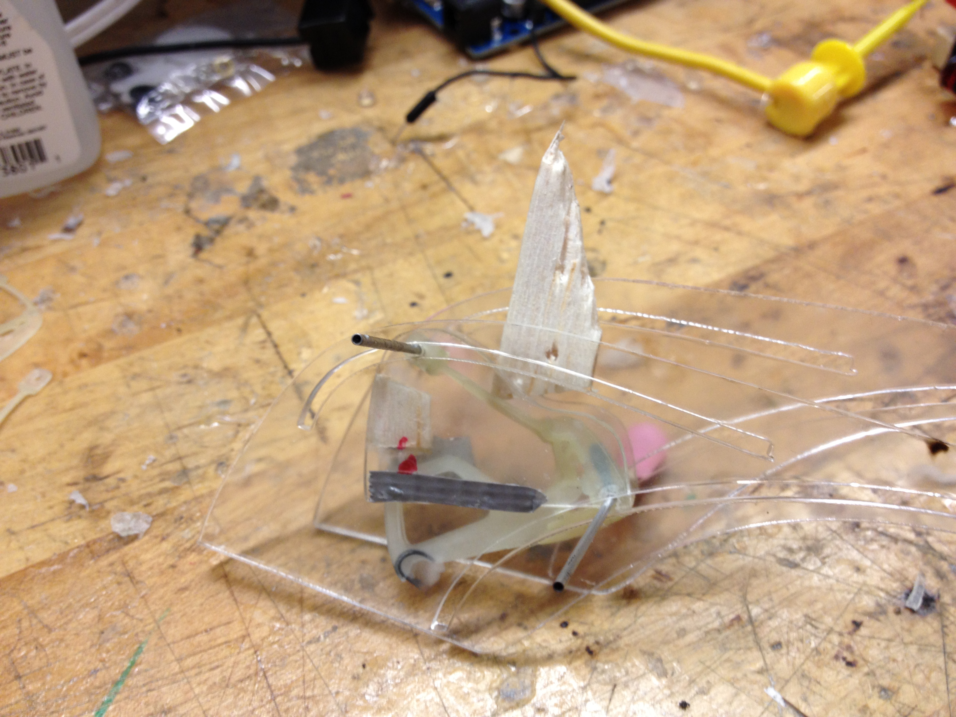
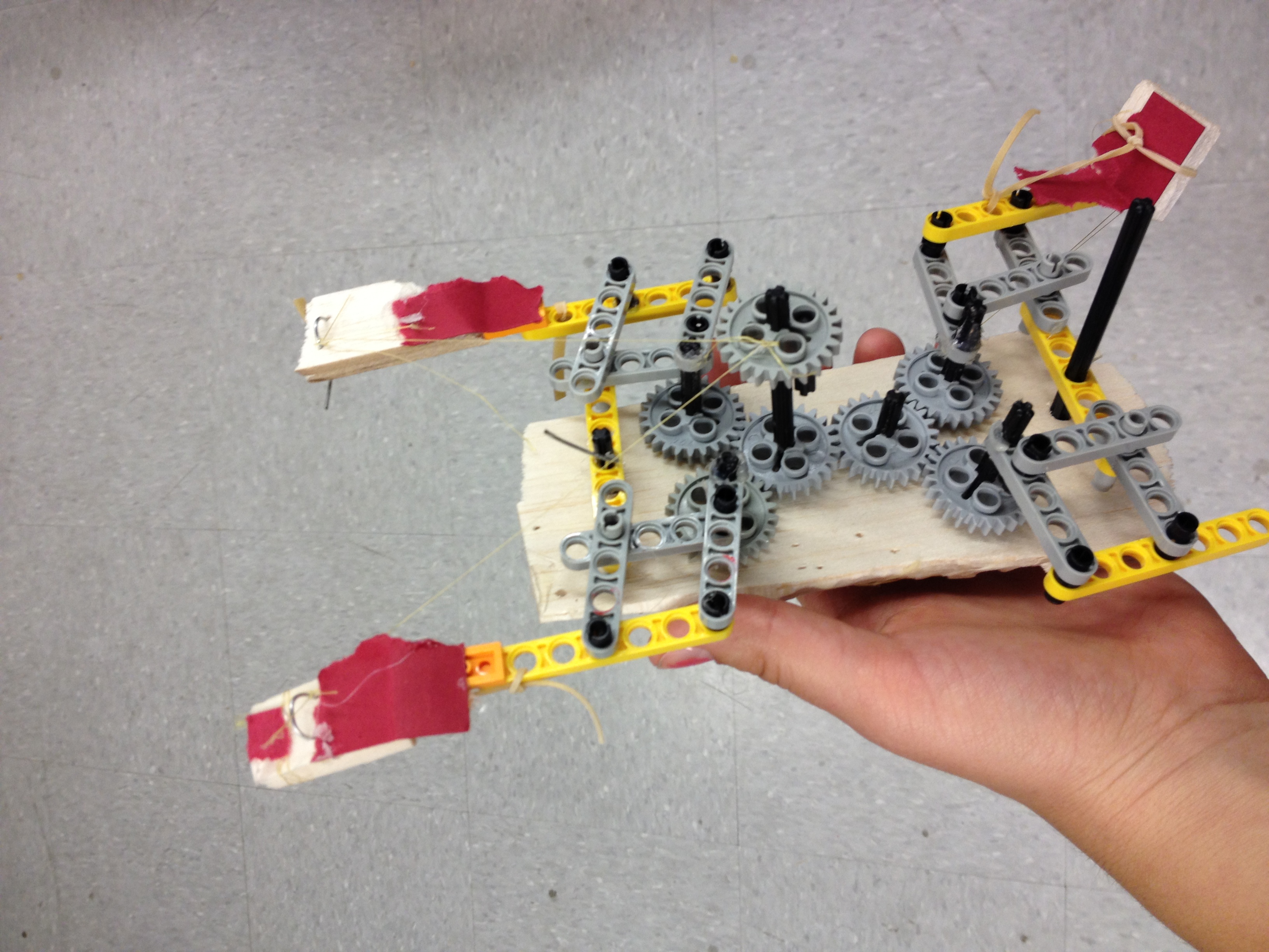
The assembled design closely resembles the CAD models.
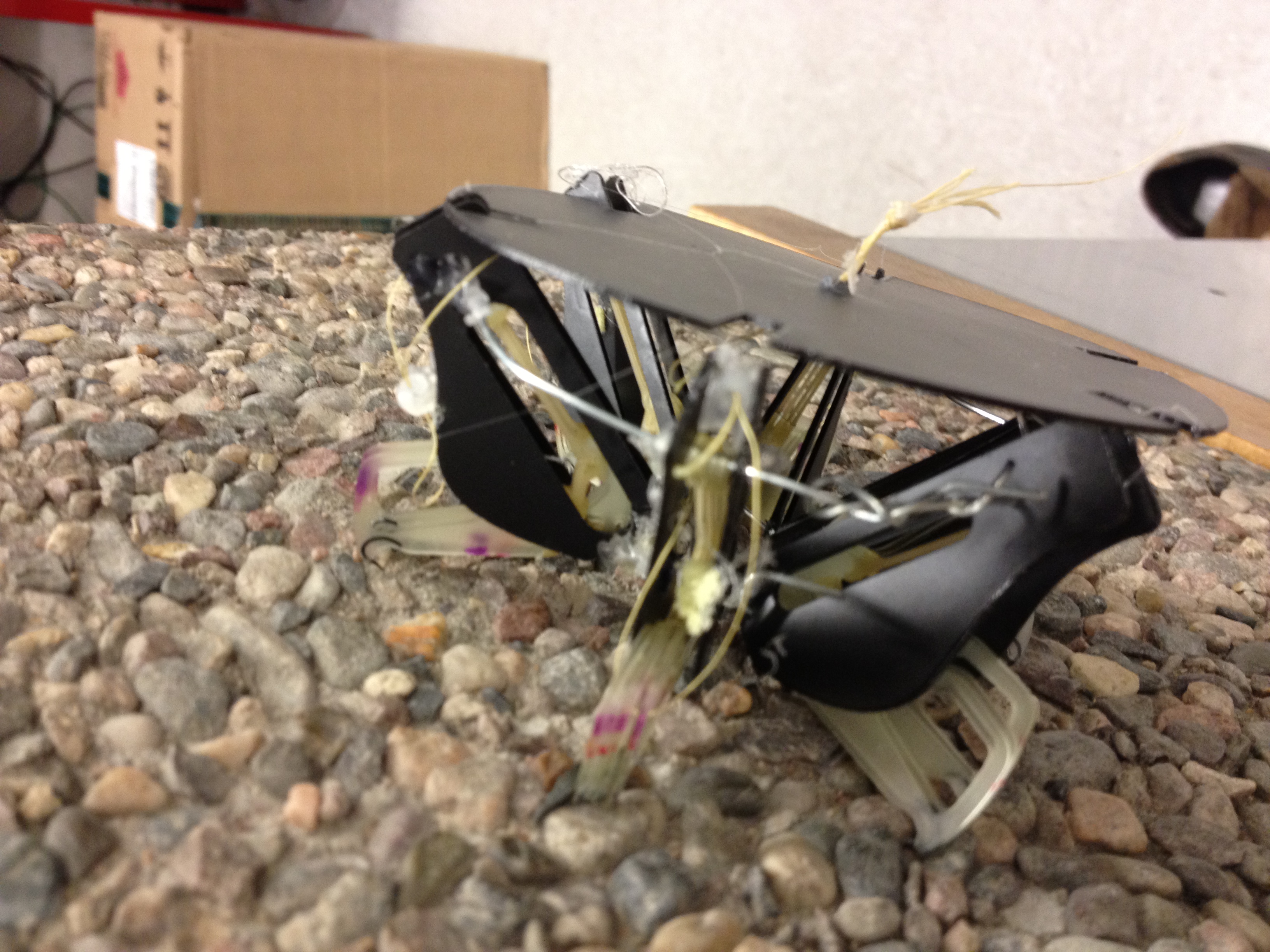
From the side you can see how the wire curves in towards the center, then is guided vertically by the tubing. One challenge may be synching all six wires together.
This design turns out not to grip as well as we thought it would. Our guess is that the hook trajectory is not ideal.
August 13th
Glued the gripper onto the body for inspiration this morning. It sticks easily onto the trunk.
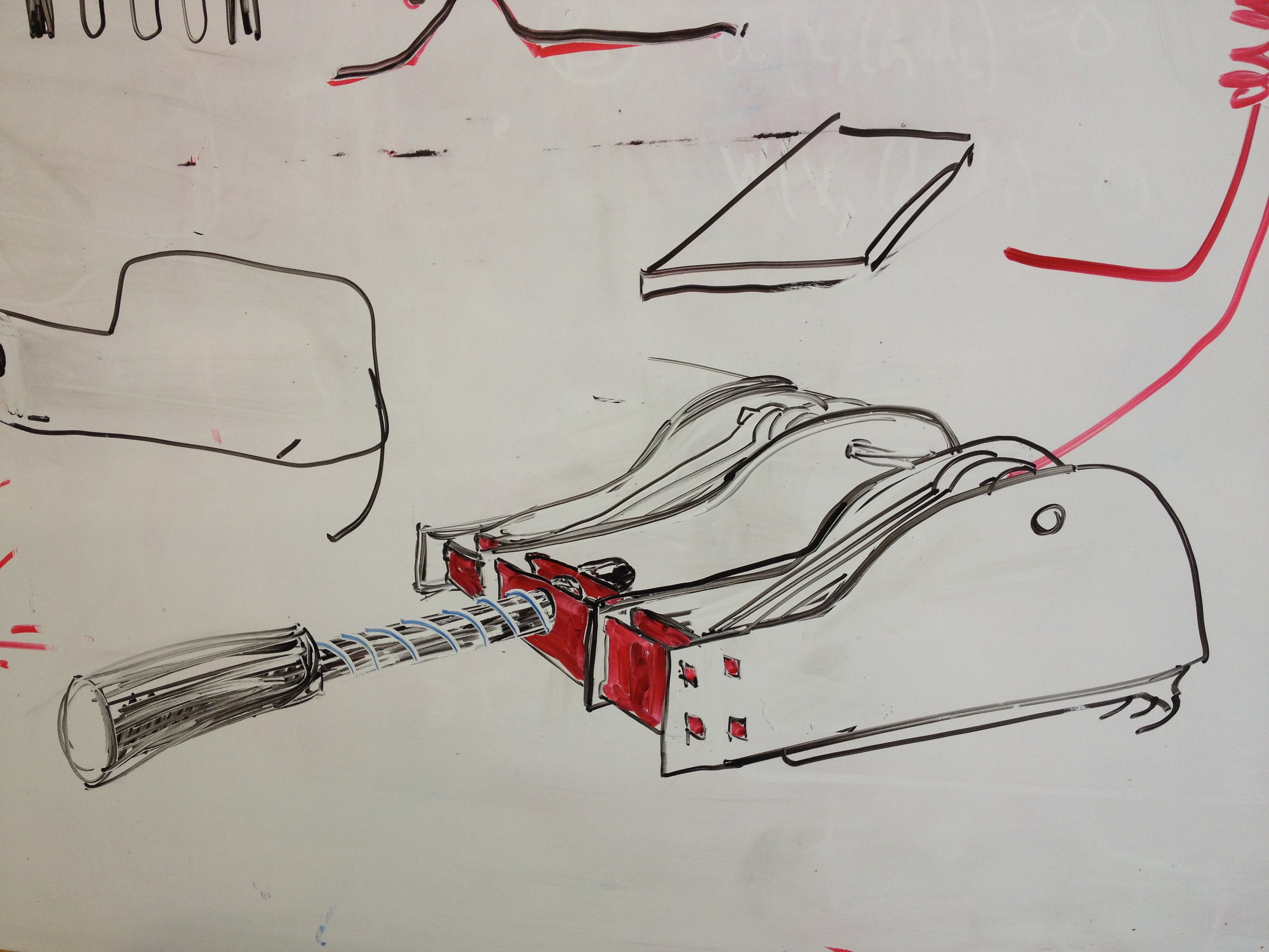
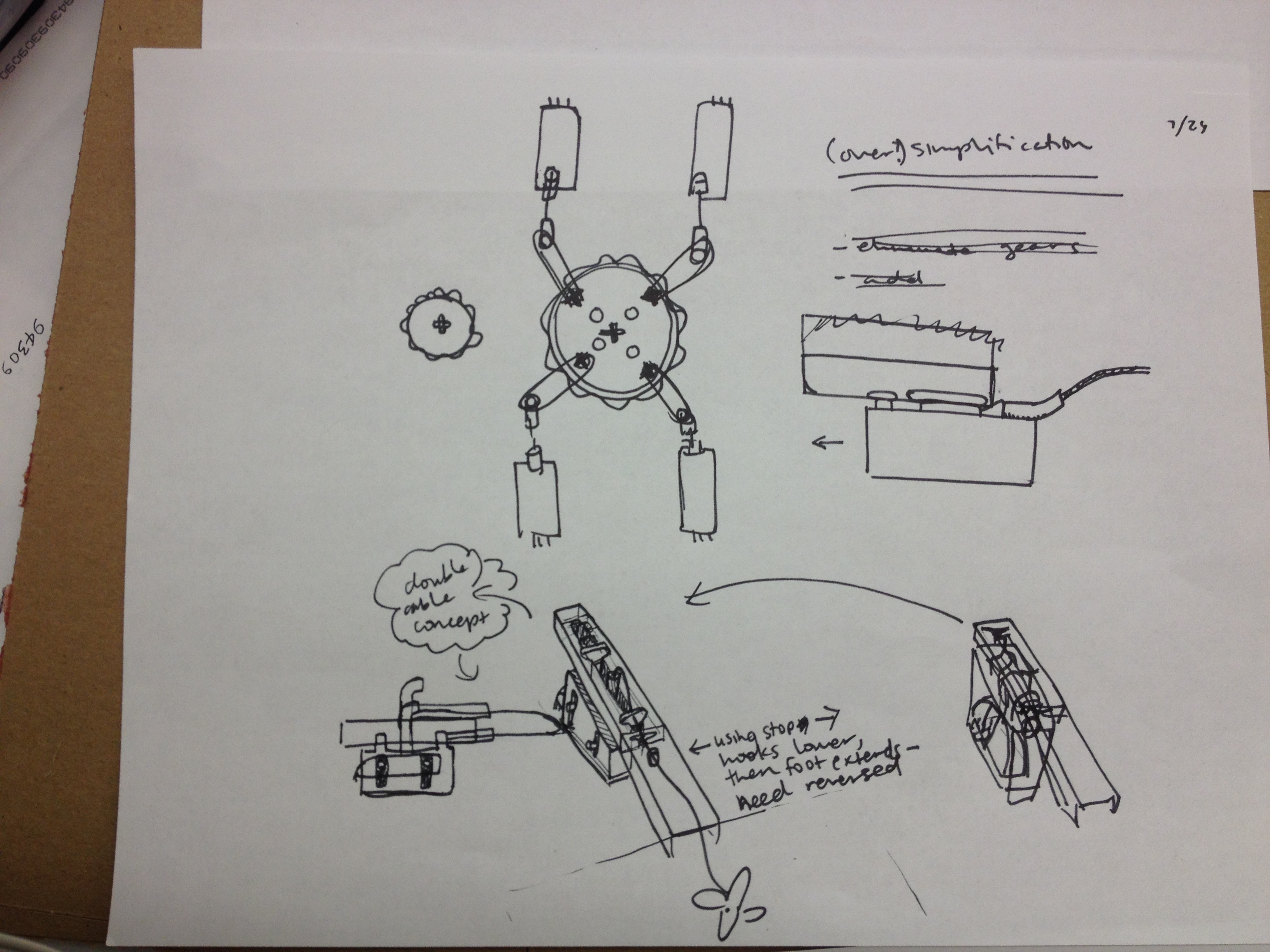
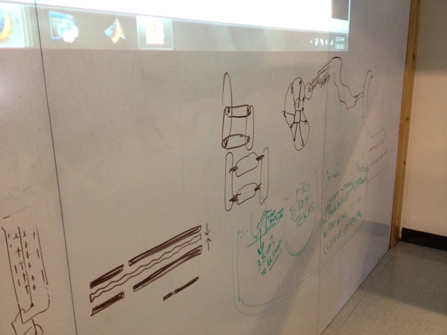
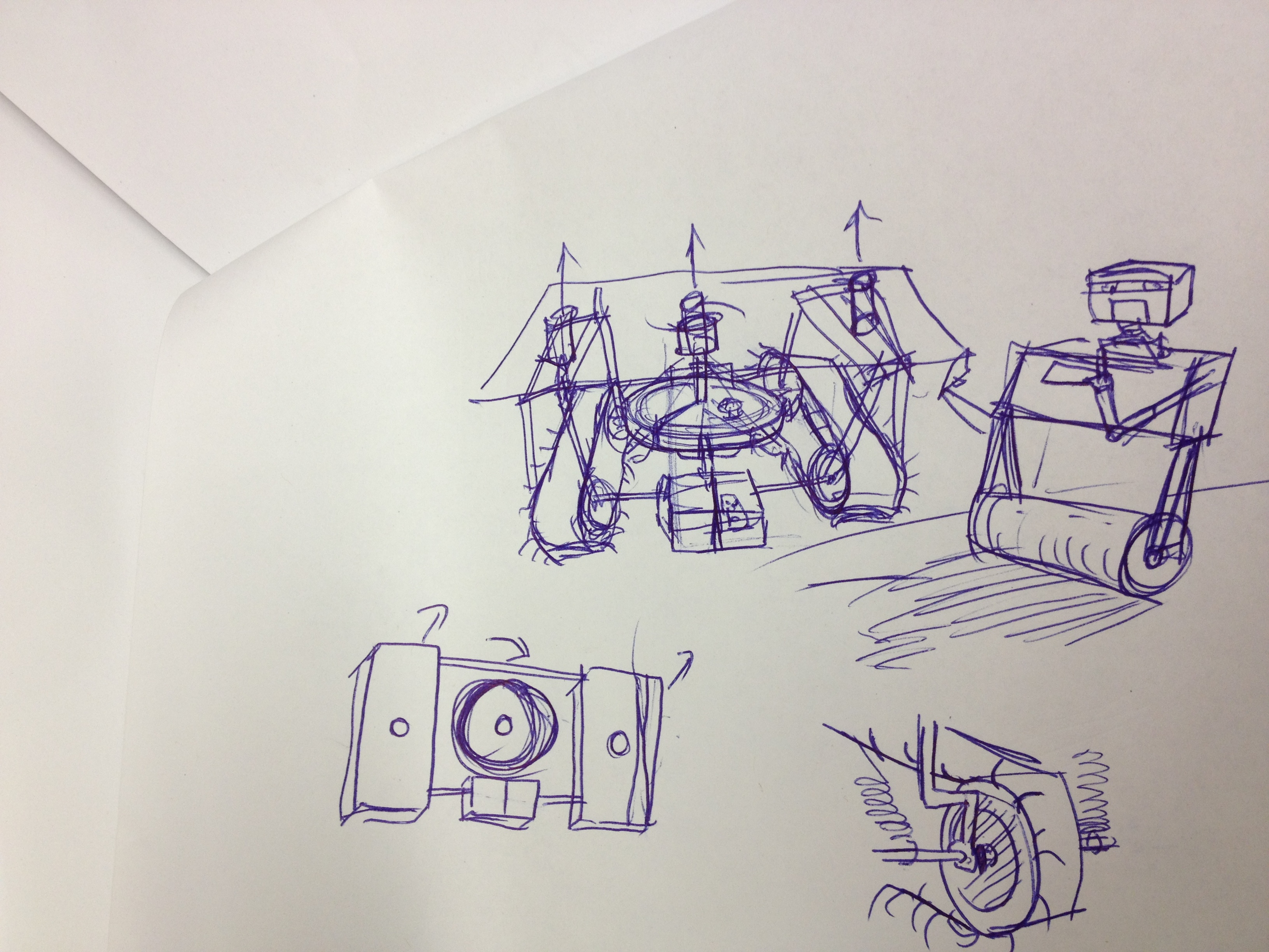
Went back to the drawing board. Needed to control the way that the cables are pulled, and guide them. My first attempt, is the concept without the guides.
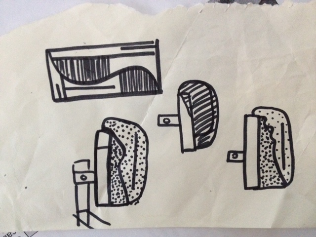
And the paper/pen solution.
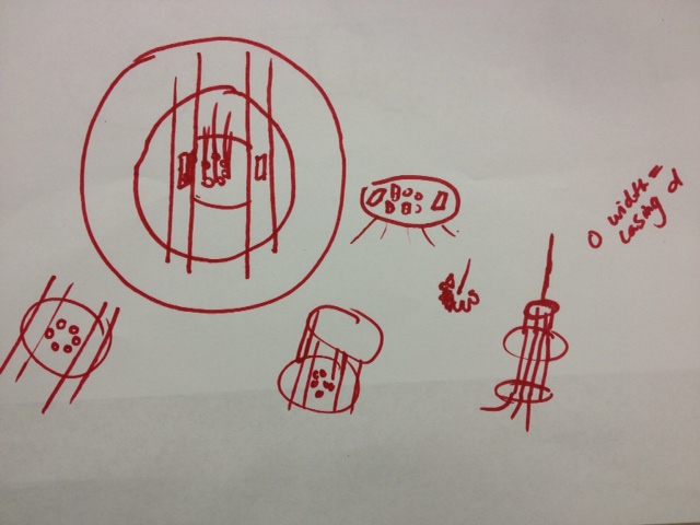
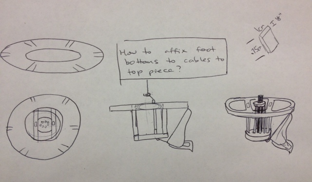
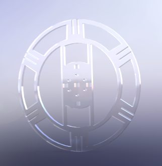
New Solidworks designs based on cable guide concept.
Also, continued hand paper readings.
To do:
Order of motion: Expand, attach front, detach back, contract, detach front, repeat.
Finished steps: expand, contract.
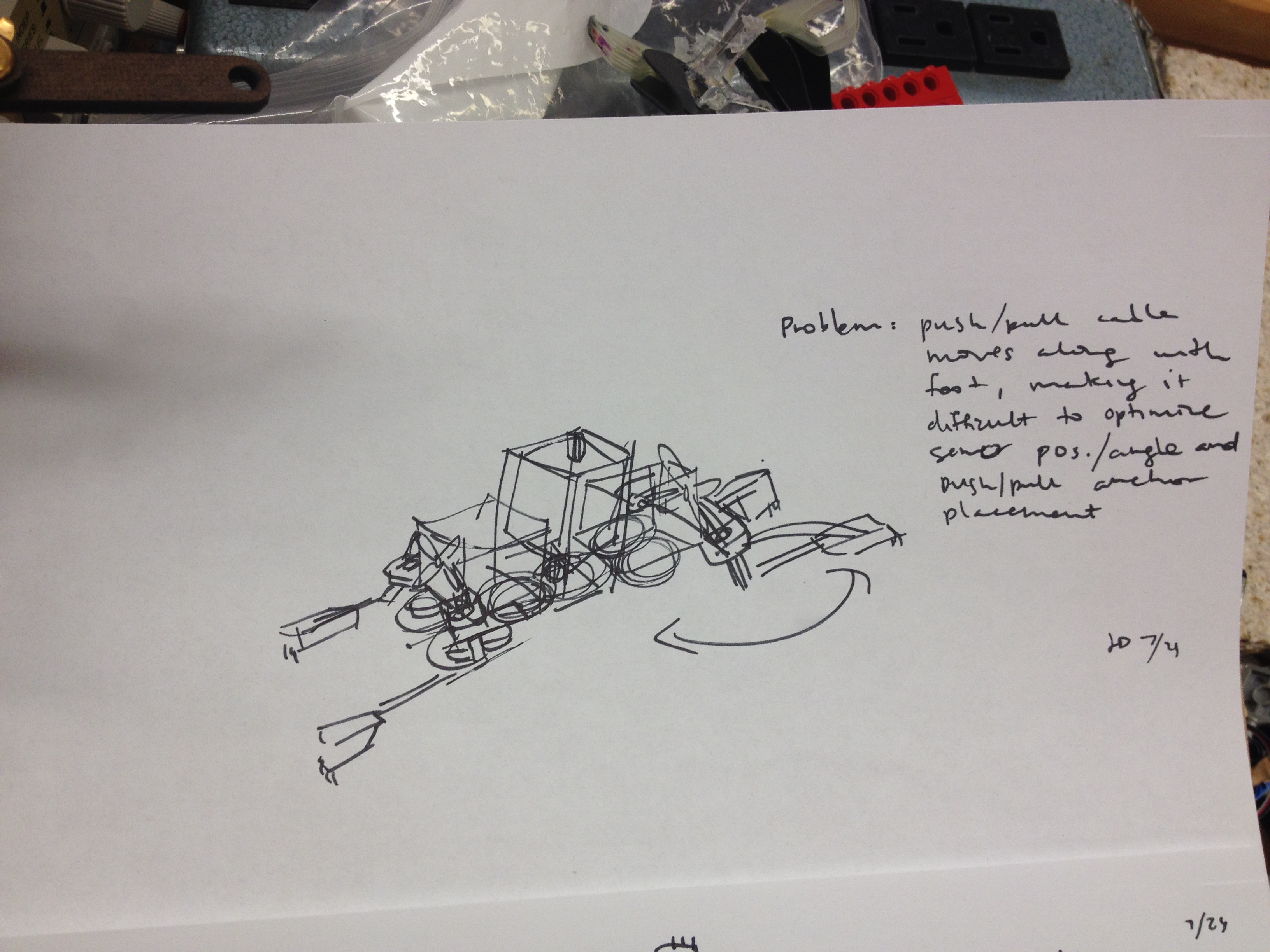
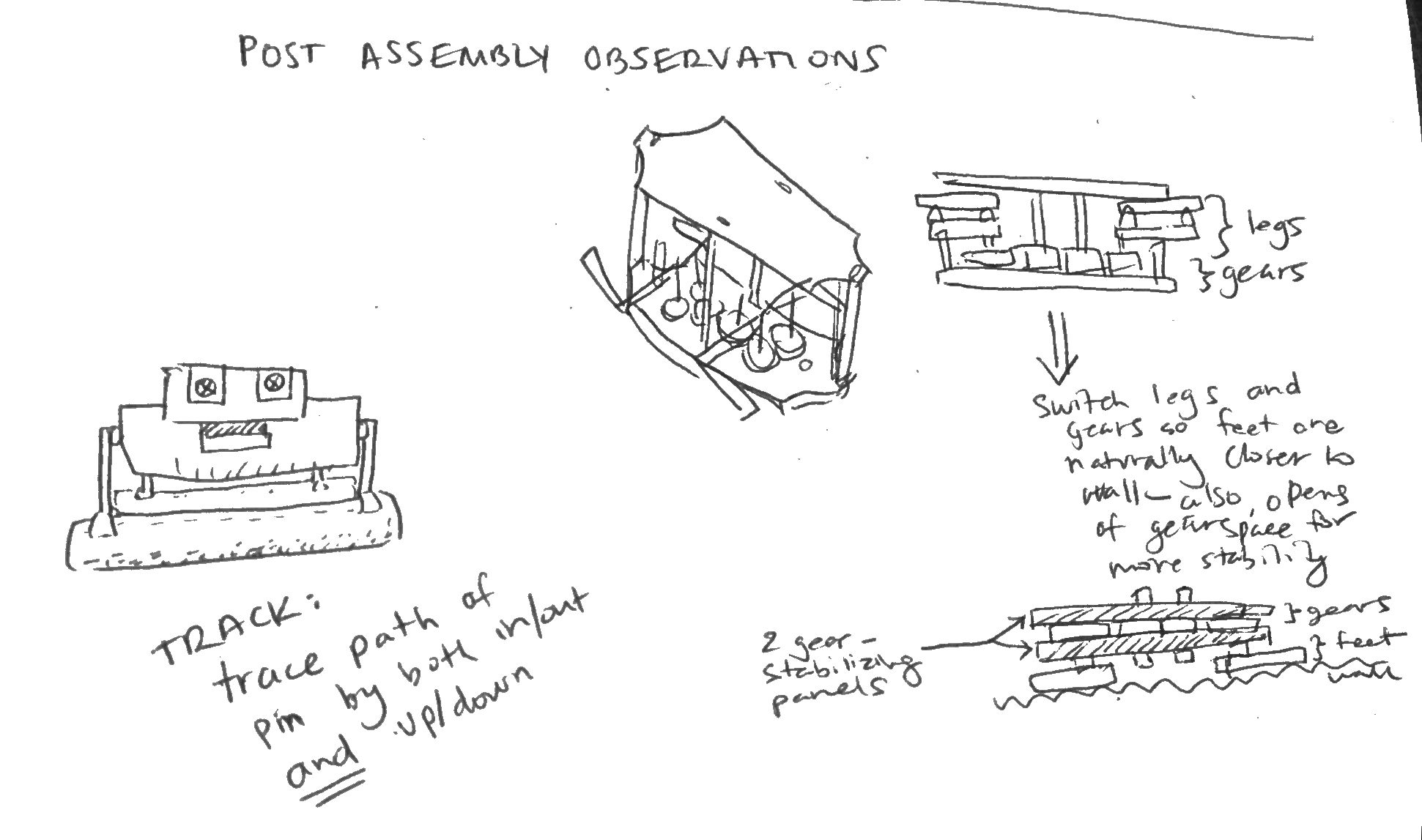
Regarding attach/detach front/back: current design prevents equal force push pull on hooks; also, hooks shouldn't move out and up but in and down.
August 10th
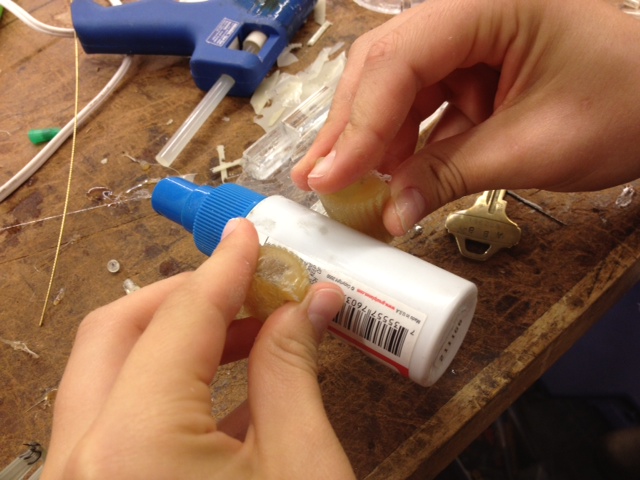
It was a little floppy so I added a plastic backing, and let it extend a bit beyond the tip for a fingernail effect. The fingernail was a bit too aggressive.
Instead, I spread out a thick layer of superglue and sprayed accelerant on. This quickly reinforced the back, and coated the previously weak fingertip to make a minimal fingernail.
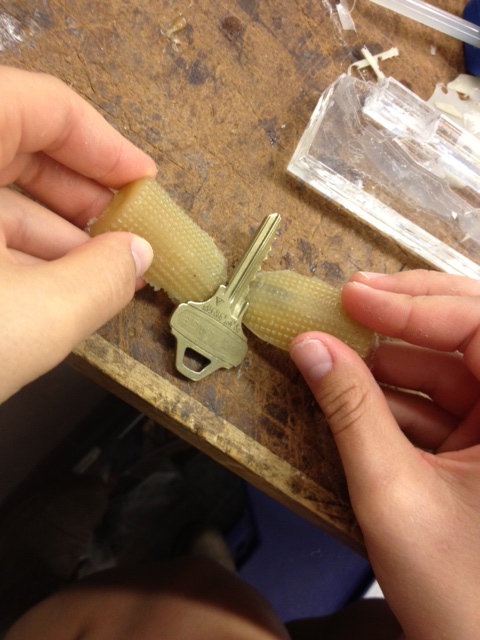
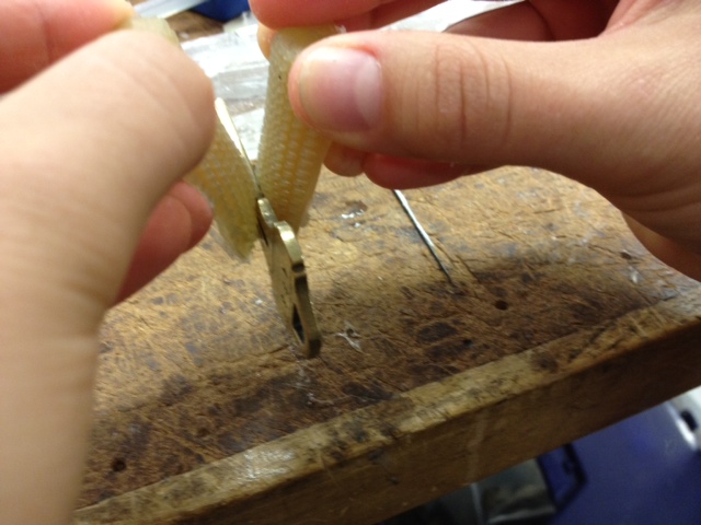
The fingertips (when I operate them), can pick up a key, or a bottle.
Thinking about another iteration. It's unclear to me how well the bone geometry is affecting the tips' ability to grasp smaller objects, so I'll need to think about that a bit. Could the entire thing work better at half scale?
---
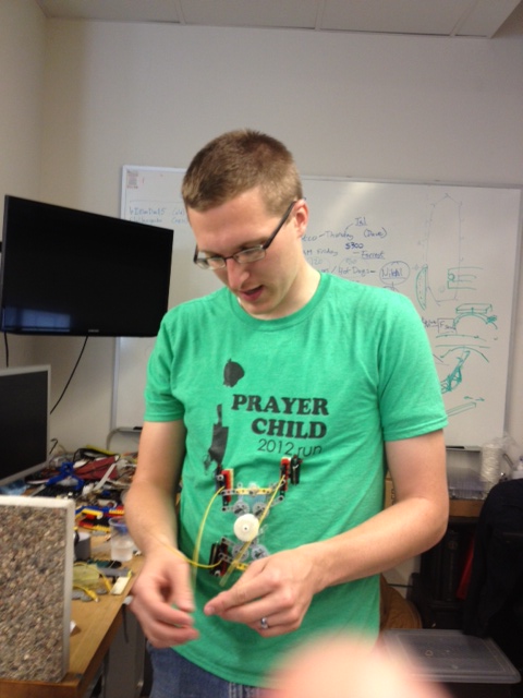
Tried to finish this in one hour...took a little longer than that but the result is a baby bot that can inch forward and turn left or right with the help of two servos.
August 9th
I am really excited to read the Meshworm Paper (A Peristaltic Soft Robot With Antagonistic Nickel Titanium Coil Actuators).
Okay, so halfway through the first page I realized I don't know what the real difference between IPMC, EAP, NiTi SMA is, much less peristaltic! So I think I owe it to myself to do some background reading.
First off, peristaltic. According to Wikipedia: "Peristalsis is a radially symmetrical contraction and relaxation of muscles which propagates in a wave down the muscular tube, in an anterograde fashion." Ok, so I actually knew that motion, just forgot the word.
IPMC: "synthetic composite materials that display artificial muscle behaviour under an applied voltage. Other limitations include the requirement to maintain ion mobility through hydration or other fluids." Sounds like it would be good for water dwelling robot creatures?
EAP: "are polymers that exhibit a change in size or shape when stimulated by an electric field. The most common applications of this type of material are in actuators and sensors. A typical characteristic property of an EAP is that they will undergo a large amount of deformation while sustaining large forces...The field of EAPs emerged back in 1880, when Wilhelm R�ntgen designed an experiment in which he tested the effect of an electrical current on the mechanical properties of a rubber band.[2] The rubber band was fixed at one end and was attached to a mass at the other. It was then charged and discharged to study the change in length with electrical current."
NiTi SMA: found a SMA training tutorial
http://www-personal.umich.edu/~btrease/share/SMA-Shape-Training-Tutorial.pdf
Excerpted from Tutorial:
"1. If the design needs more force than the original specification, what should be changed in the spring design?
Answer: Wire thickness can be increased, coil diameter can be decreased, and number of coils can be decreased.
2. If there were more coils than what was originally designed for, what could that change?
Answer: Deflection could be increased.
3. If the wire diameter were smaller or larger, how would that affect the design specifications?
Answer: If all else is the same, force could be increased with larger diameter wire and vice versa.
4. If the transformation temperature needed to be higher or lower, what would need to change about the shape-training process?
Answer: If the transformation temperature needed to be higher, the shape training temperature should be increased. If only a few degrees increase in transformation temperature was necessary, the shape training time could be increased instead."
---
Spent the afternoon modifying solidcam processes so that the outside component of the finger would cut properly, Eric's knowledge of the program helped out a lot.
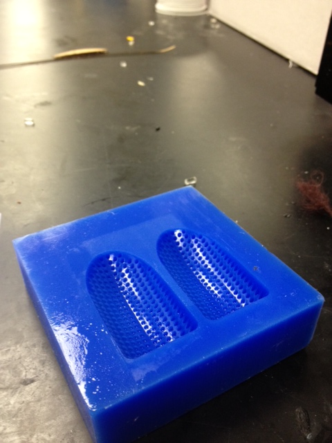
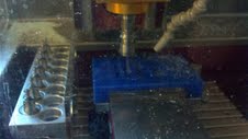
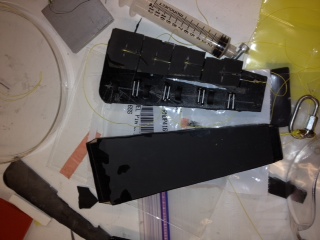
Here's the mold--it turned out really well.
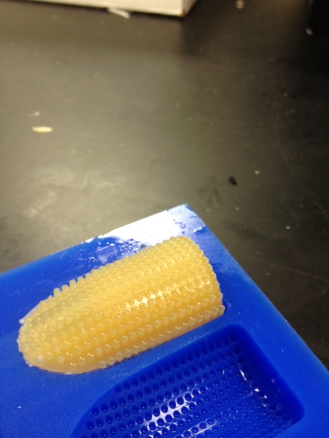
And the cured result (In many cases, the plastic did not fill the dimples entirely, but this problem can be solved by vacuuming post pour.
August 8th
It seems that dear Raoul is more prolific that I'd ever imagined.
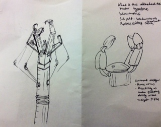
Modified gripper for push-pull activation/release.
Notes (Robotic Grasping and Fine Manipulation, Cutkosky): " --Grasping requires strength and control only in closing the gripper; very rarely is power or precision needed in opening. --when we pick up objects with our own hands the grip we choose often depends more on what we intend to do with the object than on its shape or surface properties -- "
Machined wax for bone, and cast with 3 plastic. Sturdy and easy to remove from mold.
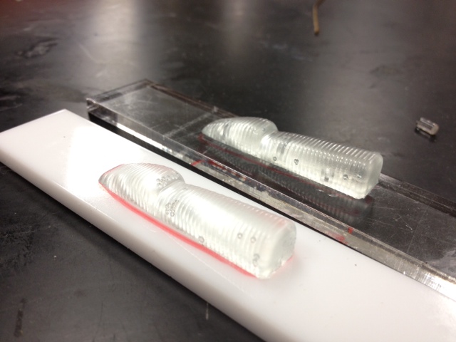
The bones are attached to acrylic so they don't sink into the uncured soft plastic. Next time, I can machine out a slot for the bone to sit snugly in.
August 7th
Trying to look into finger number/positioning this morning.
About to read: The thumb: Guidelines for a robotic design Maxime Chalon, Markus Grebenstein, Thomas Wimb�ock, Gerd Hirzinger Institute of Robotics and Mechatronics, German Aerospace Center (DLR), Wessling, Germany.
Notes: The wise words of John Napier "the hand without a thumb is at worst nothing but an animated spatula and at best a pair of forceps whose points don't meet properly."

MRC: That is a different John Napier. The one with the thumb quote is: https://www.nytimes.com/1981/01/11/books/the-thumb-is-the-hero.html
Quotes:
--the Twendy-one hand, the Shadow hand, the Gifu hand
--the objective of the designer is to obtain a functional thumb, and not a mechanical copy of a biological system...Indeed, observing the great diversity of thumb sizes and shapes, it can be hypothesized that the exact values of the mechanical properties of the thumb are not the key of a functional design
--Table 1, Distance Ratios between the Phalanxes Lengths
--The Metacarpal-Proximal joint has a trochlear type with an important lateral and rotational (twist) degree of freedom. This under-actuated twist motion augments the contact surface during power grasps and improves the fingertip pulp orientation during pinch grasp.
--Several prosthesis have been developed to replace the trapezoid/metarcarpal joint. They mostly consist either in a simple spherical joint or a ellipsoidal insert
--2)The opposition motino is provided by the TM joint and is the most important joint [lowermost dof joint]
--4) The TM twist motion improves the fingertip pulp orientation during the power grasp
--6) A large opening angle between thumb and index improves reachability but can degrade maximum applicable forces
--The mobility or the immobility of the DIP joint has almost no influence on the score
--The fourth degree of freedom improves the fine manipulation capabilities
--The TM joint has 2 DOFs and can be implemented as a spherical joint
--The twist actuation appears to be too complex with respect to its benefits
--In order to provide a maximum contact surface between the finger phalanxes and the objects, the ratio of the length of the bones should follow an anthropomorphic scale
On another note: Continuous Wave Peristaltic Motion research serves as inspiration for an active gripping method for the gripper device that we've been working on for a while. Researchers use a crank mounted on a custom printed piece that alternately contracts and releases wires in a way that causes the structure to undulate.
http://biorobots.cwru.edu/projects/softworm/
In the afternoon, Hannah and I go to the TLT and I witness Hannah's first solo CNC Levil run. Go Hannah! I read the tech sheets and decided to use the 3 instead of the 9, because it cures faster and is white--pretty superficial reasons, but the physical/behavioral properties are similar enough anyways. We'll cast the hard plastic tomorrow morning.
August 6th
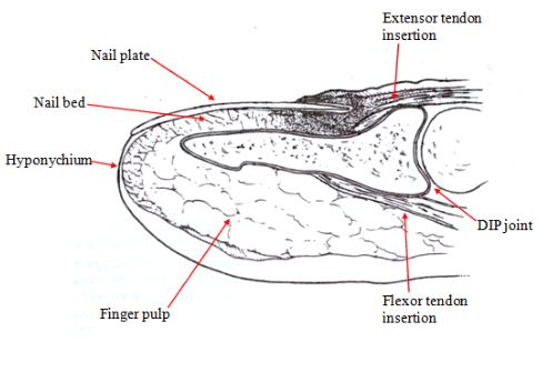
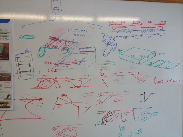
Last week, I looked at illustrations of, and read about, finger anatomy. I observed that the bone is hooked at the tip, and a soft, round tissue surrounds this bone; there is also a fingernail.
I'd like to incorporate texture to the finger, but I haven't decided whether this should belong to the interior, hard structure, or the exterior, soft structure.
I believe I may model the bone in a hard plastic, slightly exaggerating the hook and valley in the bone; then I'll have a rounded finger-like surface in the softest plastic, with tiny textures for gripping friction; I've noted that a fingernail is important for tipping objects up, so I'd like to put a thin aluminum fingernail on fingertip to prototype optimal nail shape.
Hopefully Barrett or Hannah can help me use the Levill to make my first models.
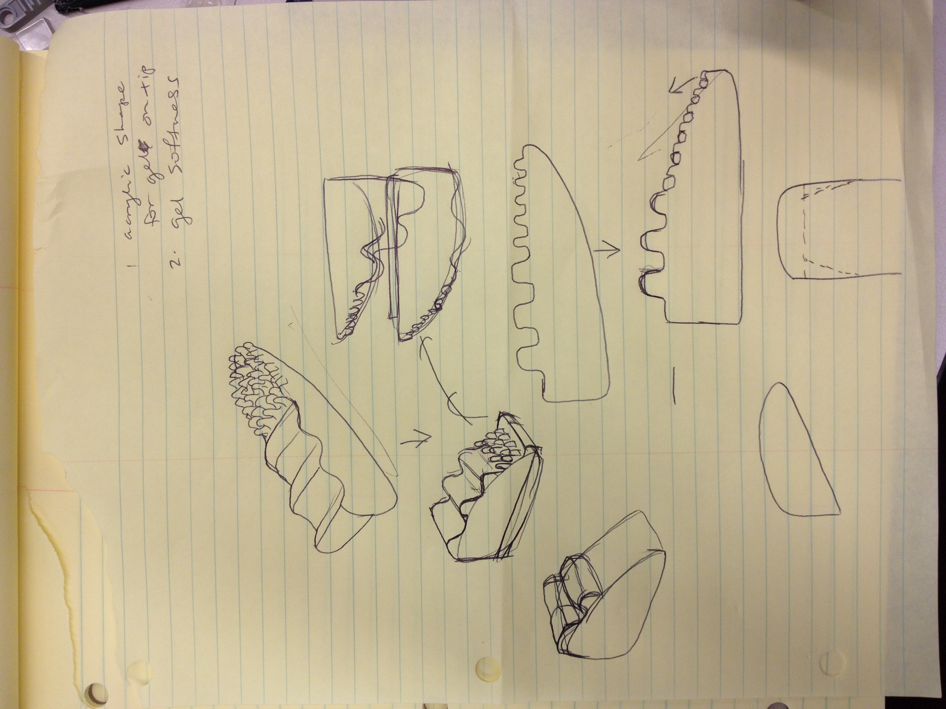
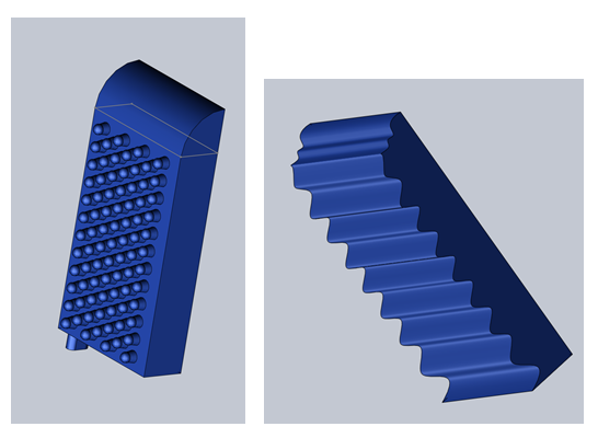
I learned about fingertip anatomy, and here is my fingertip model response.
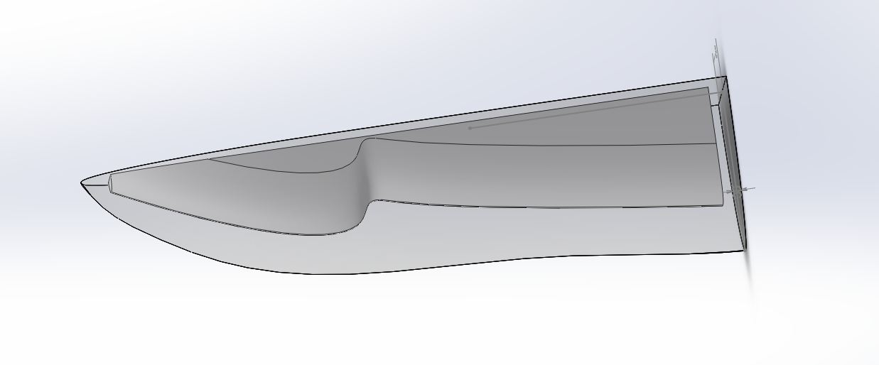
I'm having trouble making a model for the exterior that has the texture that I want, that can be machined, and that can be rendered in AutoCAD. I'm trying different variations of Sketch Circle/Boss-Extrude/Offset from Surface.
There are a few design aspects to remember as we move forward with integrating the sensor and the tip.
Wire stress relief: because the sheet will be in multiple strips, and each strip will have two wires, the finger tip must make physical accommodations for the wire in a way that will reduce stress. Possible solutions include post-machining a hole into the hard plastic of the interior element, feeding the wire through the hole, and allowing the soft gel to seep into the hole during casting; including a flat reinforcement surface normal to the direction the wire may be pulled in; a knob that follows the wire out of the finger; etc.
Bending: the sheet bends in one direction, should it bend in the x or y direction? also, keep in mind that it will eventually be cut into strips and not be a solid strip, which will diversify bending options. How does the curve/texture of the outside fingertip component affect the sensor's ability to detect pressure/etc?
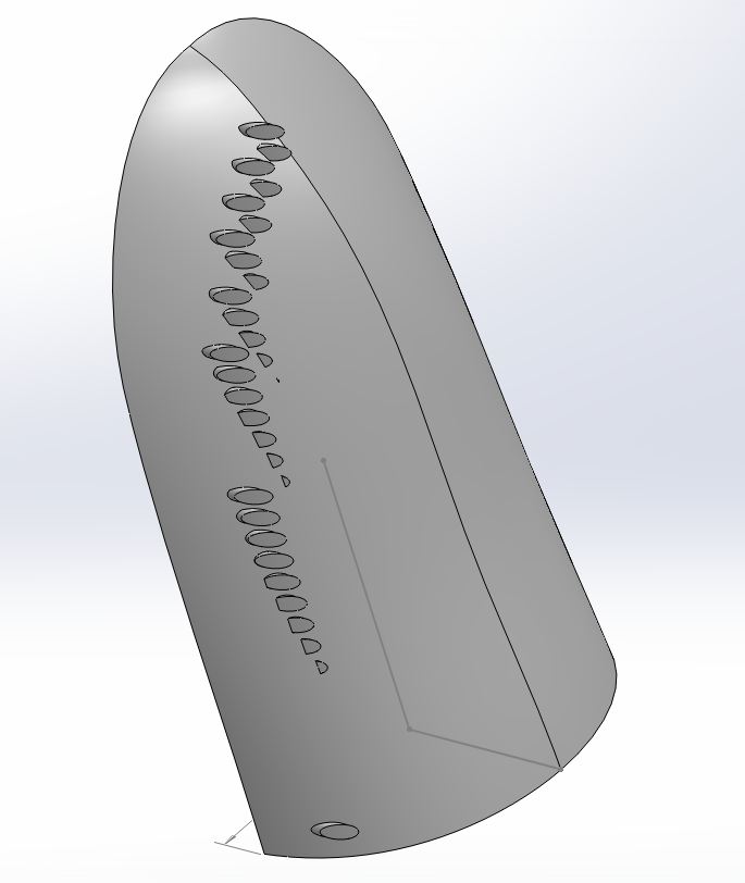
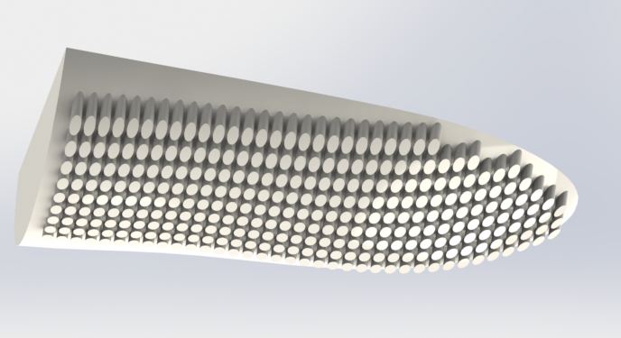
Finally, a few hours later I finished modeling the texture.
August 3rd
Began AutoCAD modeling of fingertip in response to the findings that Hannah presented at lab meeting.
Lab cleanup--lots of Lego organization and table razor blading.
August 2nd
Attended the GEM annual meeting and attended Grad LAB, an initiative to increase graduate school attendance by minorities in STEM fields. Lots of fun! Solidified my conviction to go to grad school.
August 1st
Fingertips exploration with Hannah.
One observation I had is that, when a finger presses against a table, the front and side of the finger compress much like the pad does. In the prototype, there was no compression at the tip, because the tip ended with acrylic. So Hannah showed me how the CAD model worked, as well as how to cast the tips, and we tried out a new design that allowed gel to seep around the front and side of the finger tip. I learned how to mix the two gel components and how to vacuum the mixture to decrease the amount and size of bubbles. That tip works best so far. It uses the softest plastic (10) and a rounded mould.
Until July 31st
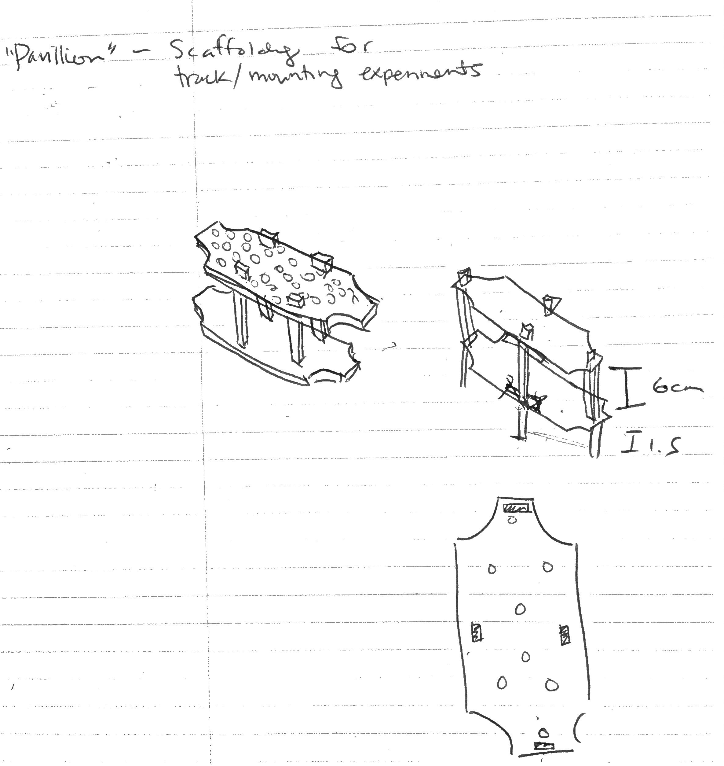
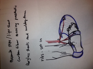
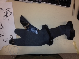
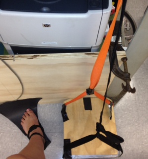
Planned a simplified foot mechanism to attach to sticky bot fusion.
Cut and built the first version of this simplified foot. Here, I was trying to create an extension motion with the foot, but the track turned out to be too complex for the action needed.
Here I've made a tinier foot that works very well, although it does weigh a bit. I discuss some of the lab's earlier lightweight foot mechanisms. One such foot used tiny rubber bands to change the motion on the way out and in.
This is the inspiration for the next foot that I built. It inches forward by extending against the pull of the rubber band. Once it hooks into the wall, it's back end is allowed to spring forward (inchworm-like motion).
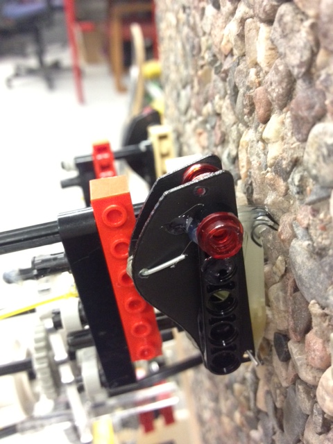
Next, branching off of Marks idea to use a modified plane for the entire robot to decrease weight and complexity, I built a few feet that mimic the feet currently affixed to the plane, with the difference being that the hooks are no longer fixed--they can contract and grip the wall when hooks are placed in opposition on the tail end of the plane.
July 23
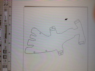
I'm trying to figure out a way to make SbF out of 2d cutouts. Here are my first CorelDraw images.
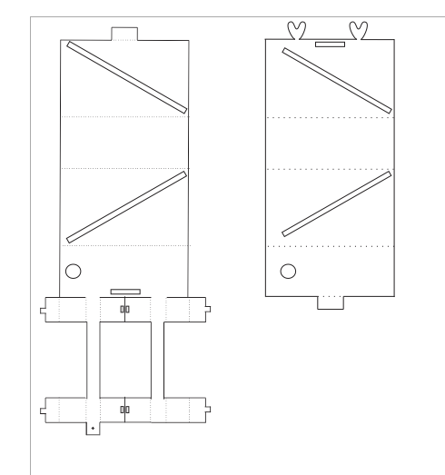
Tried using a medium thickness polycarb--it fell apart at the dashed lines. Might need to make multiple passes at different settings.
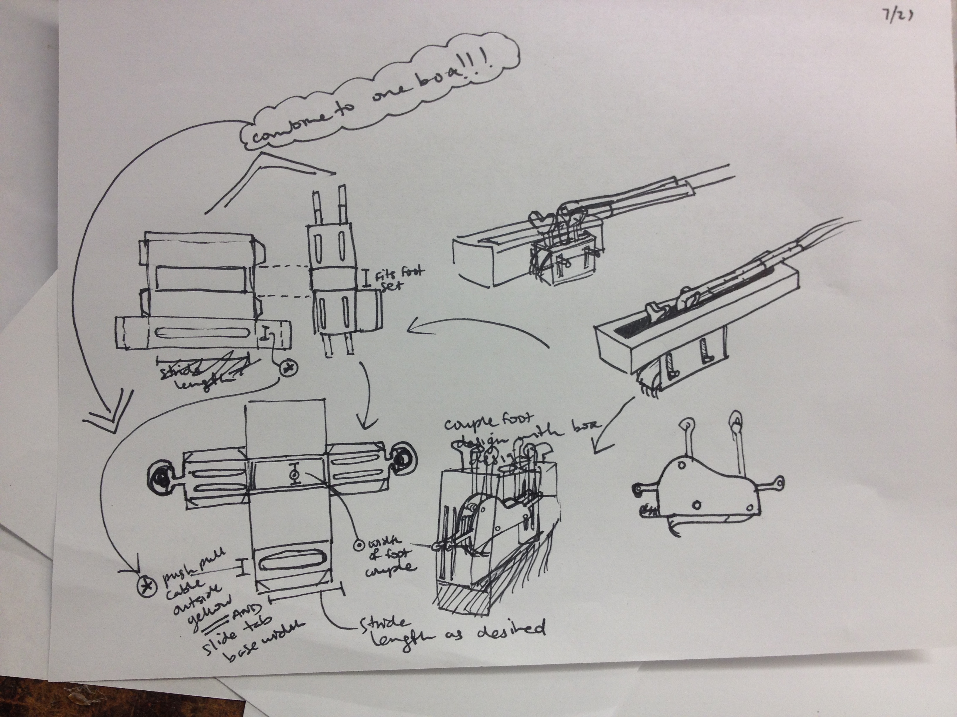
July 20
Prepared slides for presentation with Forrest.
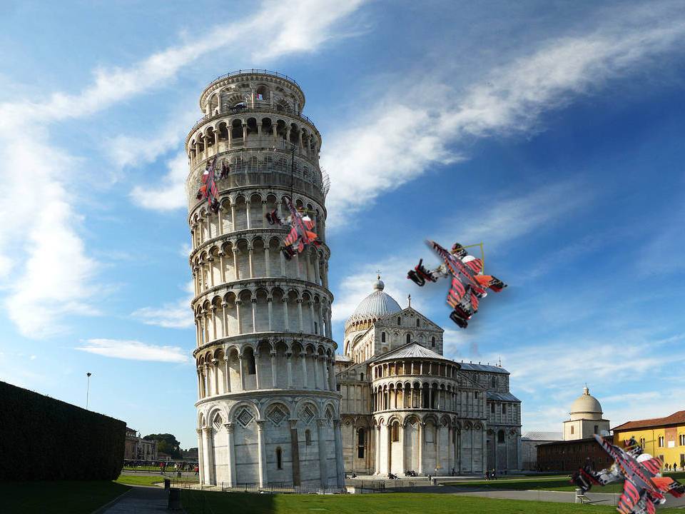
I hatched brilliant "Final Destiny" plan. Stickybot base and fighter jet modeled top. Obviously.
Talked with John about a method of making 3d robots from 2d layered, multi-material cutouts. Sounds like fun.
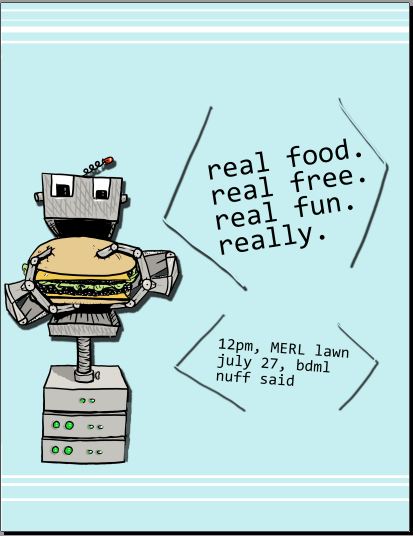
Made BBQ poster for next week. Hopefully lots of people will show up or I'll feel slightly responsible.
July 16-19
Looked at robot and pondered [life, robots, moving robots, life, killer robots].
Morgan calls the robot we're working on StickybotFusion. I'm not sure whether the robot is a fusion of sticky and bot or something else... I may call it SbF from now on.
Learned about how to make things move--thanks to Dave the mysterious "servos" and "arduinos" are becoming disappointingly less mysterious.
We decide to ditch the track idea and go back to push-pull cables. Dave has cool foot drop idea and we go for it.
Classic case of the youth not taking expert professor's advice to start with push-pull cables :)
Morgan, Dave, Forrest and I sit down and casually whip this out in an afternoon. No big.
Still trying to crack the foot motion challenge...
The robot as assembled using the acrylic cutouts.

Helped Forrest record the historical/epic jumpglide test--total 8" flight. Yes.
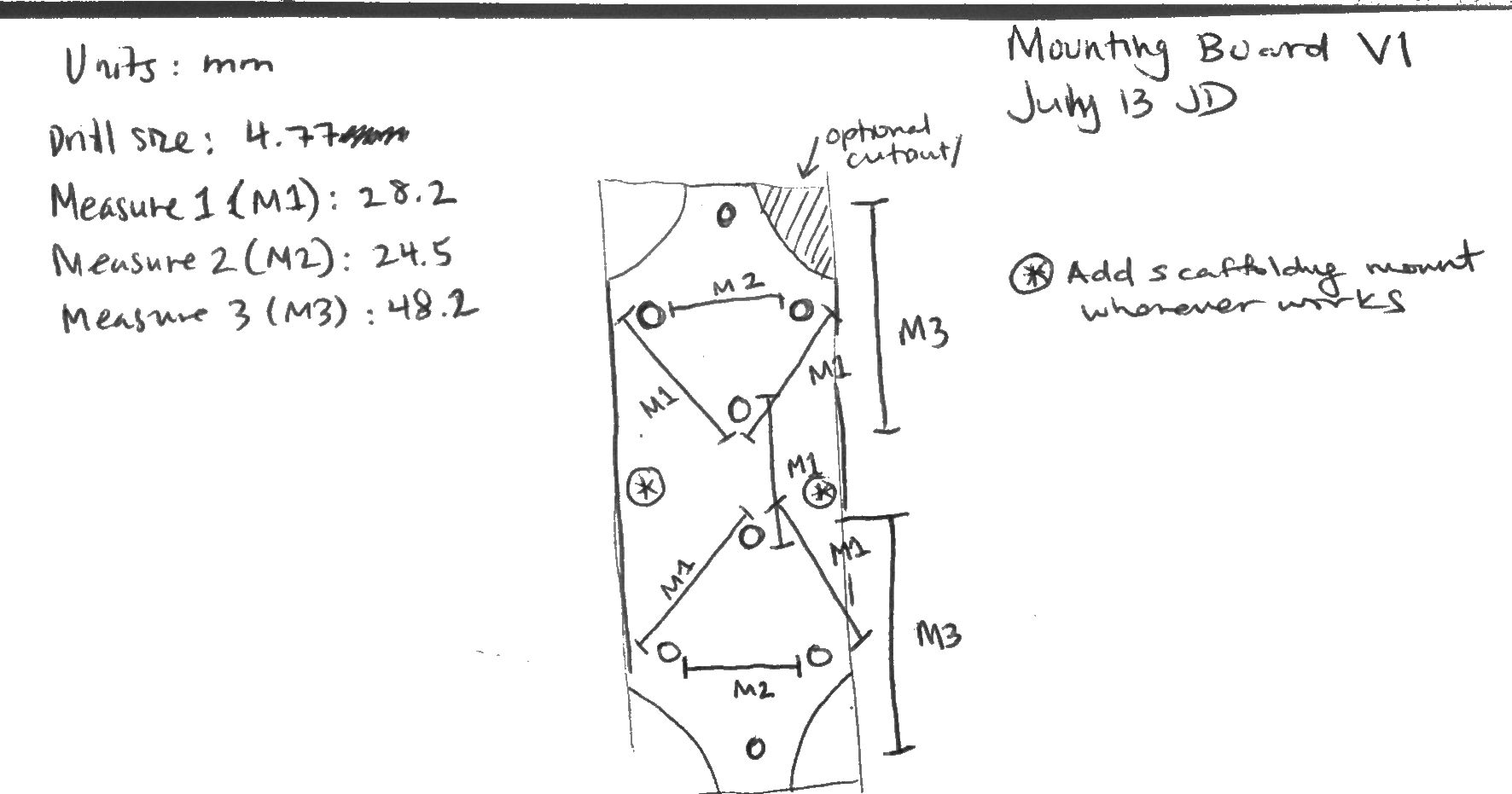
July 13 Updated blog. Yay! Lab lunch meeting.
Made my first in-practice "engineering drawing." Handed it off to Forrest--he did a great job of using my drawing to make the pieces in SolidWorks. Go teamwork that works!
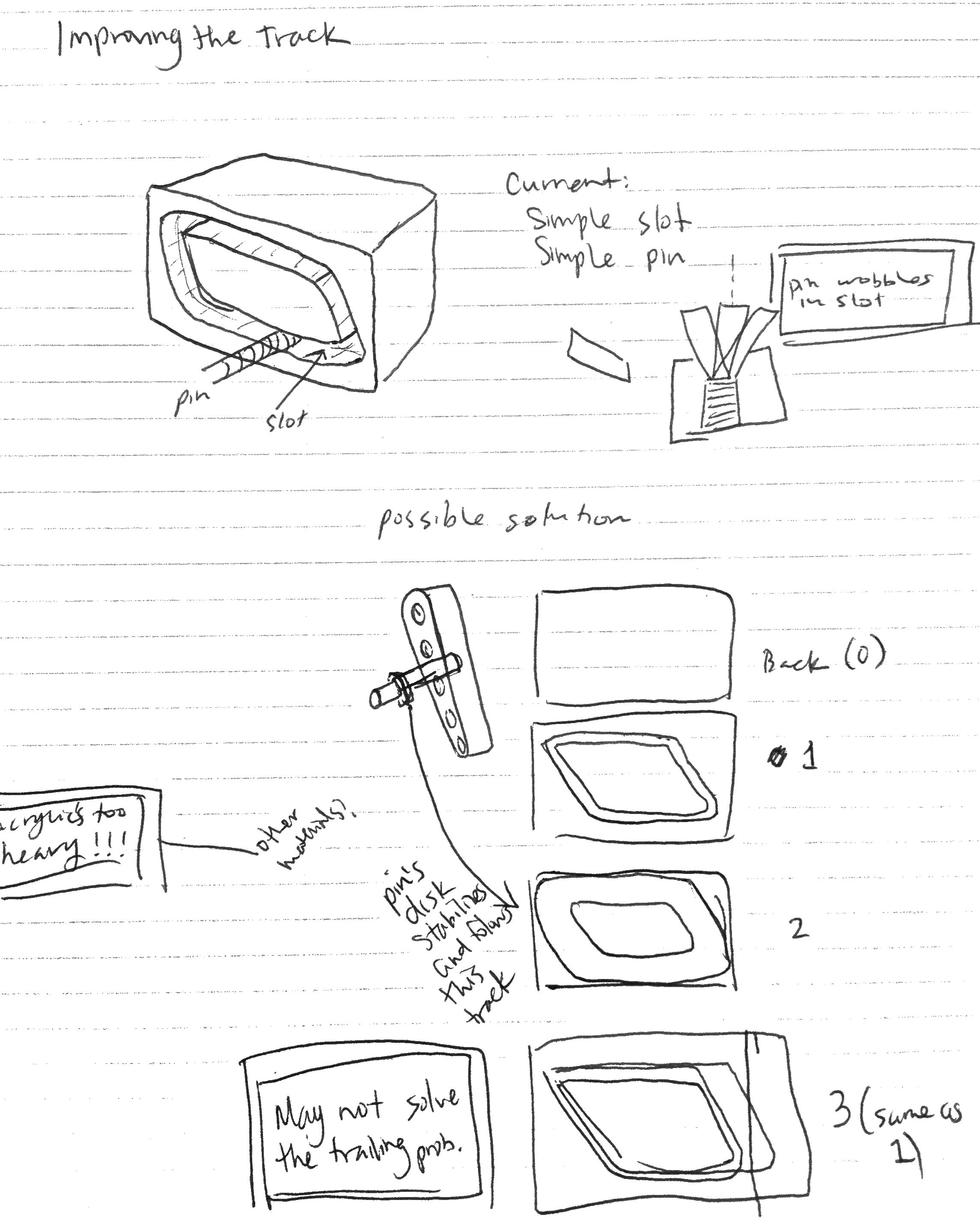
July 12 Made foot mechanism. Wanted to make a track for the foot to run along. Instead of giving the foot a lot of slop, I suggested ball and socket joints to give the foot a large range of motion. Concept wise, this was good, but as soon as Forrest and I went to cut out a track, we realized that we'd be left with a hole, unless we made a support. I solved the problem by observing that, if the track were placed on the outside, we would only need to track one motion (the path of the foot; instead of being on the inside, where there would need to be a track guide for the path of two legs). Built the track out of acrylic. It doesn't work too well so far, but I think it'll get there.
You can see the pin on the foot.
My PD side attacks--I use acrylic scraps from the track to make "necklaces."
Testing the concept; the track.
July 10/11 Prototyped and drew different perwling configurations.
July 9 Corrected gripper braces on Solidworks. Changed number of leg sets from eight to ten, and made a spacing disk.
July 6 Worked on mechanisms to get motion of the foot right.
July 5 Worked on mechanisms to get motion of the foot right, including four bar mechanisms, wire track, and push-pull cables. Played with the gripper and tried to get the furthest distance (added tail and washers).
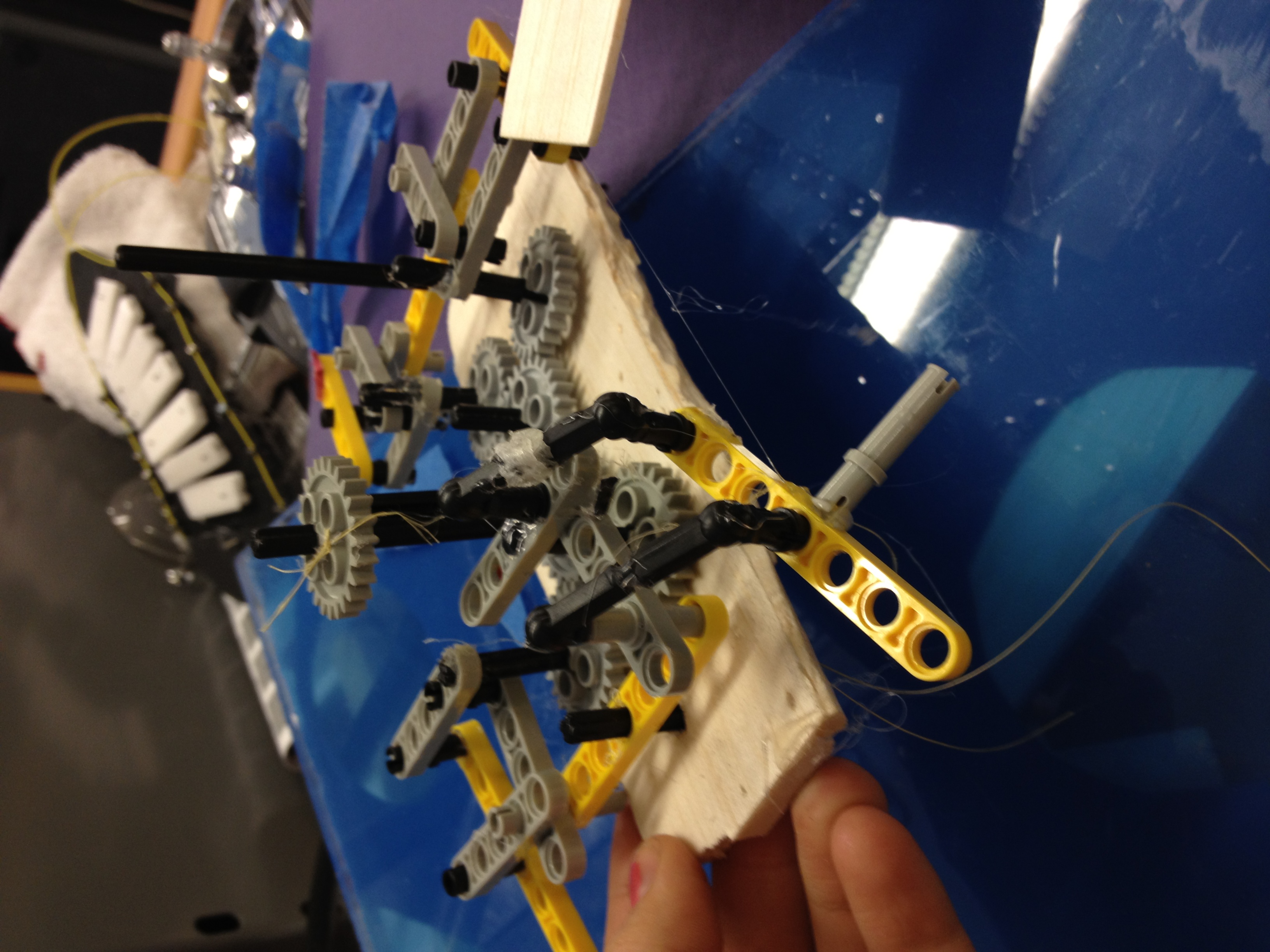
July 3 Learned that instead of one large central gear, there should be two gears. Reassembled the walker.
July 2
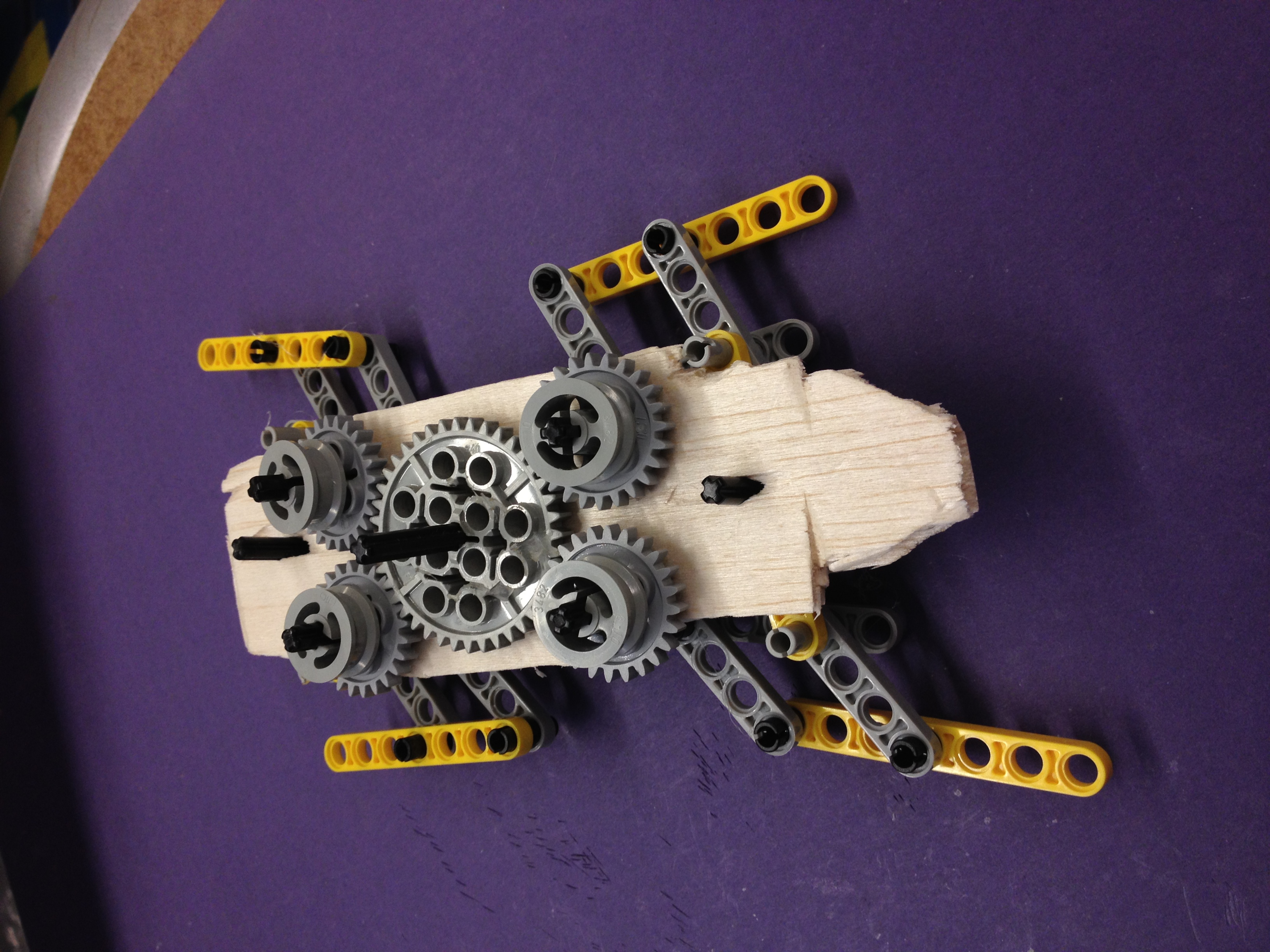
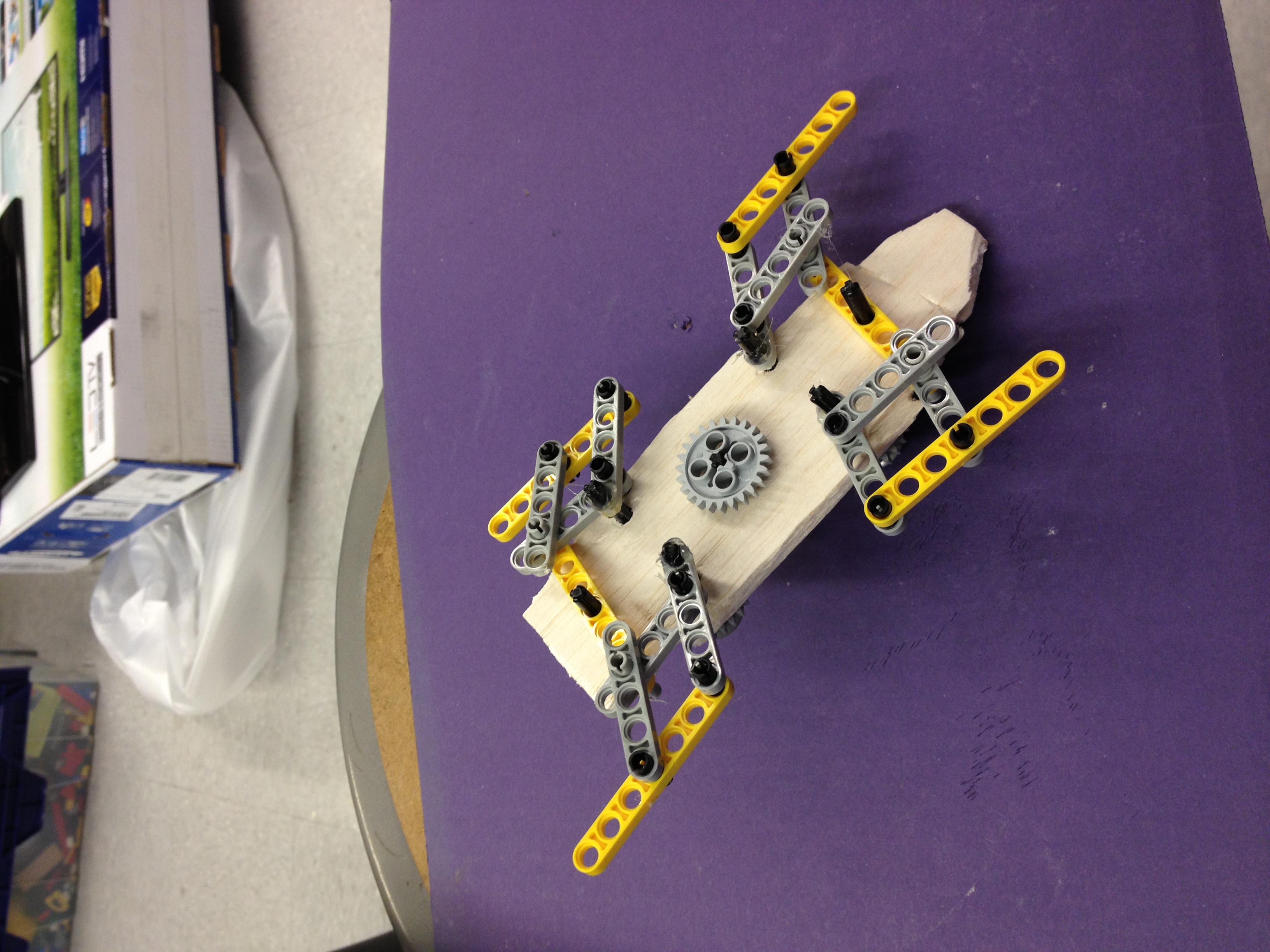
Put together the walker for the first time.
June 29 Lab meeting, Morgan and Forrest reported on gliders.
Played with Dan's climber prototype and thought about gears/cranks and other moving mechanisms.
I learned how to upload photos to a gallery. These cover the last three days. JuliasFirstGallery
June 28 Today I laser cut a side brace to replace the foamcore brace on the first iteration of the gripper. At first it didn't stick because the weight of the "spoke" on the brace was tipping the gripper away from the wall. So, I snipped the spokes off, and added a washer to the inside rung closer to the wall. This should keep the momentum going towards the wall instead of away. Then it stuck better.
I assembled Dan's climber prototype with brackets. Talked about ways to get the foot to lift up and the feet to move efficiently.
June 27 I made a circular gripper that holds onto the wall well--a good passive attachment device that is pretty reliable.
We played around with it a lot. Morgan even attached it to the tip off a glider, and it landed on the wall.
June 26
The return of the foot:
I used a tablet from Meyer to refine the foot file, and printed a test sheet on the laser cutter; "assembled" the shoe and made refinements in marker, then flattened the structure so that I could incorporate the refinements in the Corel file.
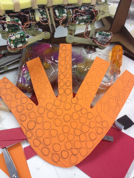
Next,thought about the fin edge of the shoe and decided to eliminate a toe-like structure in favor of circles that may complement the hand (if we choose to go in the circles instead of squares direction). But it still looks like a shark :)
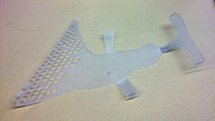
The Poly was a little stubborn and melty but it is an ok stand-in for the more versatile fiberglass sheet that we'll be using later on in the process. This iteration has holes for the third string that run vertically on the heel strap.
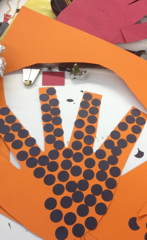
I'd like to develop the shape of the shoe further: arch molding, comfort straps, toe grips? Does this mean I should mold my foot and do a casting? An opaque black dotted sheet could be layered with a colored solid sheet to create the appearance of colored dots.
Barrett took the lab on an afternoon field trip to the TLT for a little bit of light Levil instruction. Note: use arrows and Page U/D keys, not UI buttons (the buttons move by the wrong increment); E-Stop is broken.
Levil-related links: http://bdml.stanford.edu/twiki/bin/view/Manufacturing/LevilCNC.html, http://bdml.stanford.edu/twiki/bin/view/Manufacturing/ManufacturingHome.html, and http://bdml.stanford.edu/twiki/bin/view/Manufacturing/SDMUsingPolymers.html#Multi_Polymer_Curing_and_Bonding
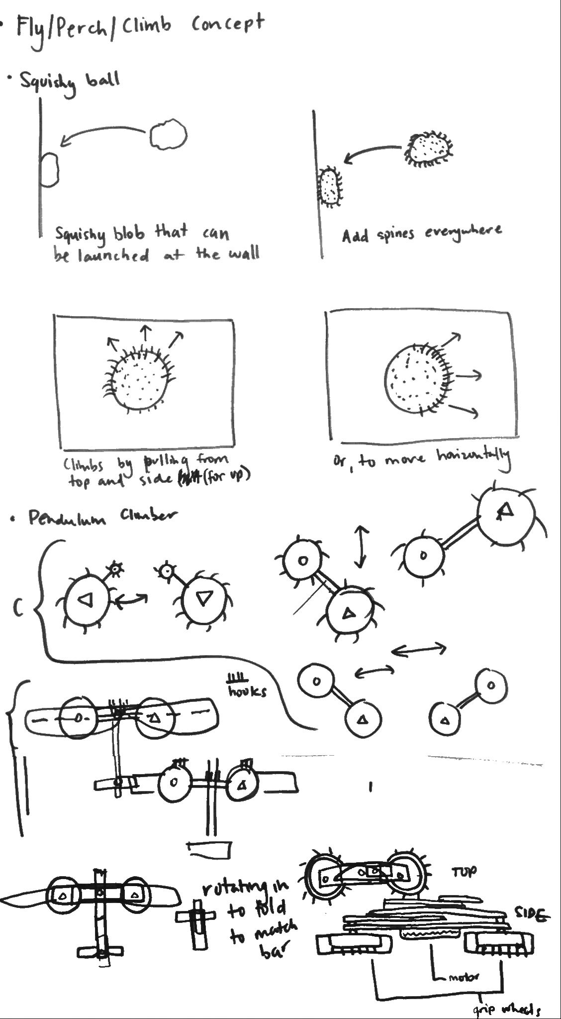
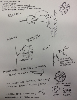
Fly/Perch/Climb:
Wingsuit Basejumping rocks: [[http://www.youtube.com/watch?v=9ATikkZPHck&feature=related ]]
Squirrel Aerodynamics 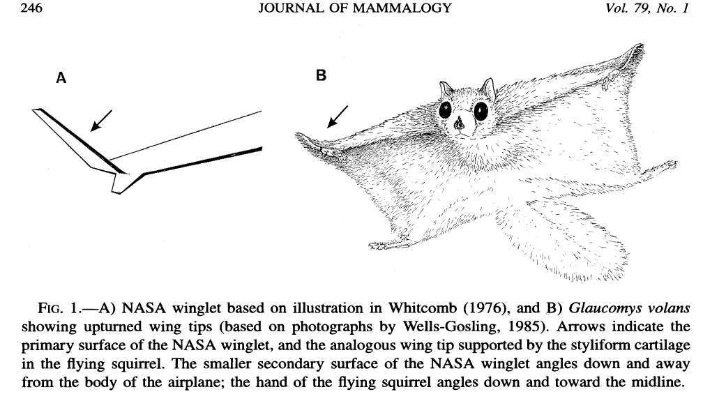
June 25
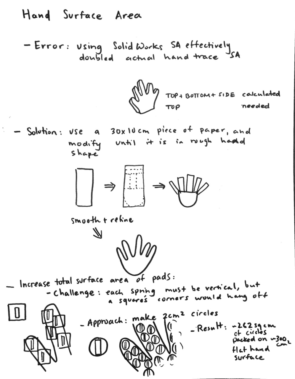
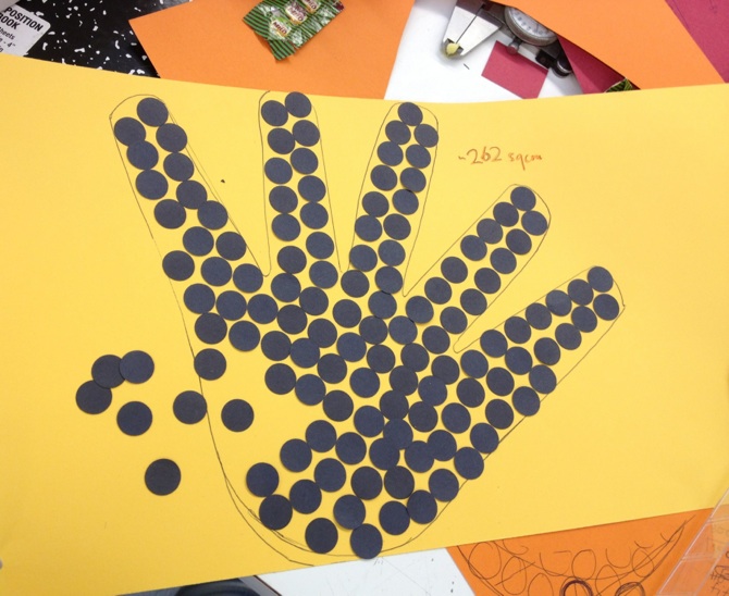
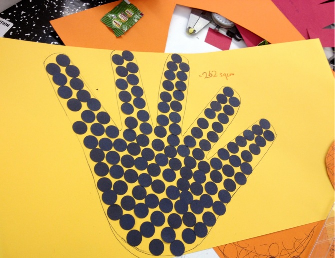
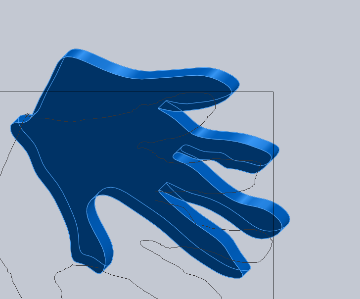
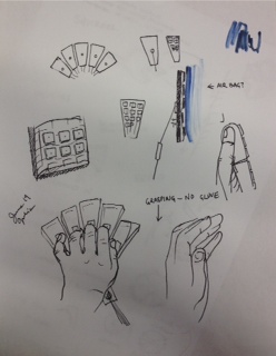
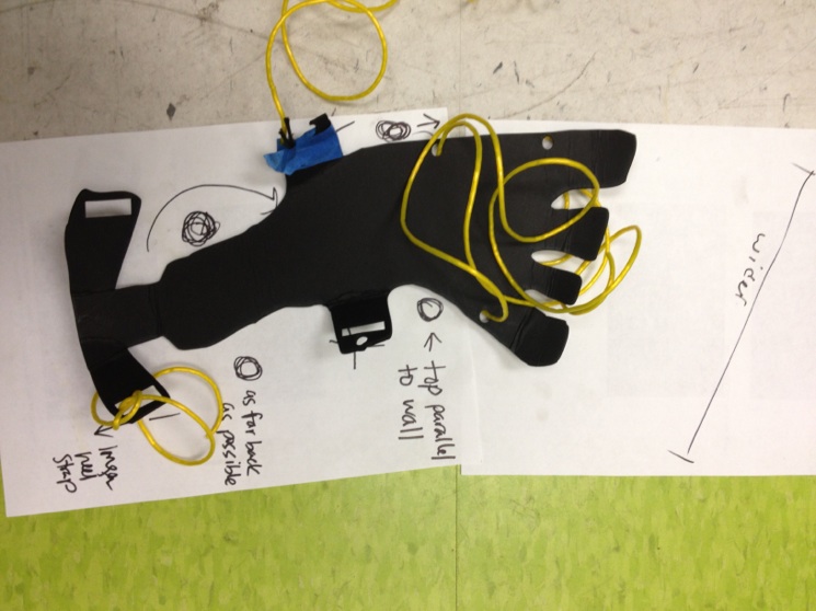
First try at using the 30x10cm piece of paper to make a hand.
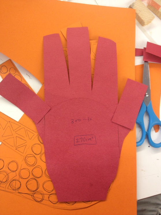
Second try at using the 30x10cm piece of paper to make a hand. Also, starting to consider the possibility of using different shapes of sticky sheet (hex, circle, etc).
Whipping out the big kid math. I tried to calculate the radius needed to make a 2sqcm circle. If this is wrong, let me know!please! I'll be sad for a little then very appreciative for the rest of the day.
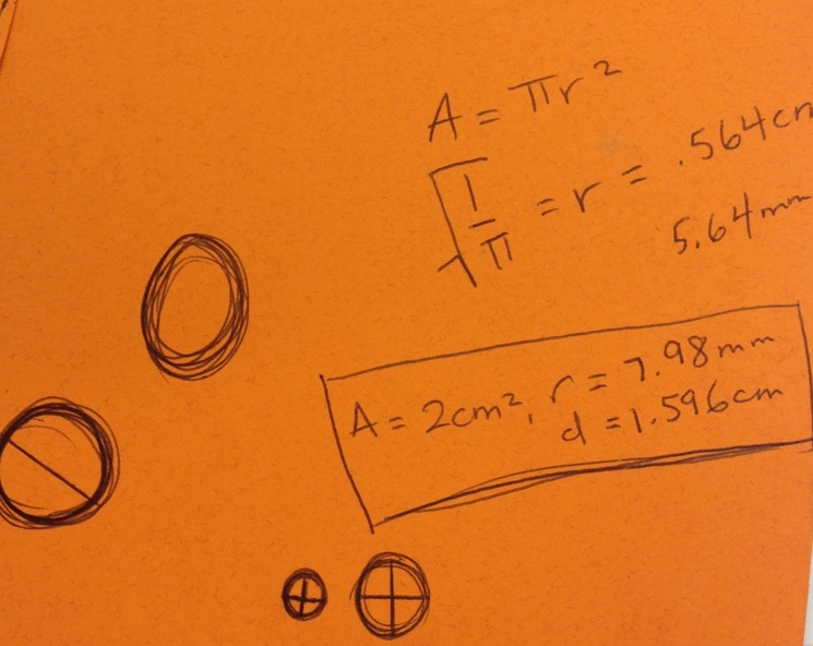
Playing with circle dots. So much fun.
Note: Choco Milo Energy Cube in last three photos.
June 22
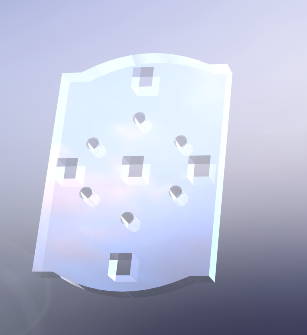
Learned objectives for underwater finger skin. Goal: embed three sensing sheets inside of a skin with a textured outside; optimize gripping texture; practice and refine mold filling process with the placement of the sensing sheets in mind.
Here are some practice finger textures made in SolidWorks.
Lunch time lab meeting to talk about flying climbing. Cutkosky reminded us to use the working, dynamic hooks when making prototypes. I want to follow the centipede design more by using hooks with springs on them.
Measured area of hands (cmsq)-- Current finger flaps: 300 Mine:371 Tal's:367 Elliot's:465
Note: maybe not super accurate considering Tal's hand is larger than mine (or maybe I have fatter fingers...). But either way, hands have more sa than fingerflaps! yay!
June 21 Lab tours.
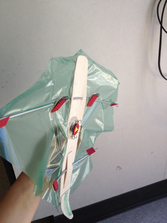
Made another prototype for tomorrow's flying/climbing meeting.
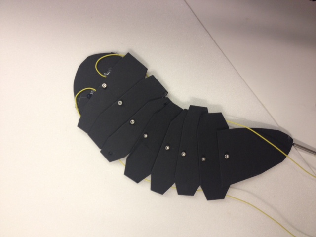
Each scale rotates. When thrown, the body hooks in the middle and the head bends back. If both chords are pulled at the same time, the body rights itself (the chords act like contracting stomach muscles). The body can be steered by contracting one chord more/less than the other. The pairs hooks that run along the inside pull inward, allowing for vertical and horizontal climbing.
"June 20"
9am sharp lab cleanup begins.
Made landing/climbing prototype for Friday's meeting. Wings; tail curved downward; four limbs; center hooks that grab and a screw that allows the entire piece to rotate; hooks oriented for hanging and for pulling motion.
 Attach 13.jpg
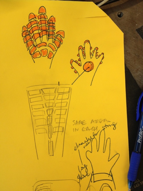
I want the hand climbing piece to be contained on a single rigid hand-shaped piece (or with adjustable fingers). This would allow for the pulley system to be eliminated. One string could be attached to the back of the hand, instead of one to each finger.
June 19
Thought a bit more about the hand.
Barrett and Dan demoed how to run the ARM-H hand. Learned about its unique features (under actuation in tendons, joint sensors) and grabbing challenges (slipping while grabbing some cylindrical objects.
Went with Tal to the TLT. She worked on the Coreldraw model for the glass-climbing spring mold and showed me how it works.
Joined lab for the perching/climbing idea workshop.
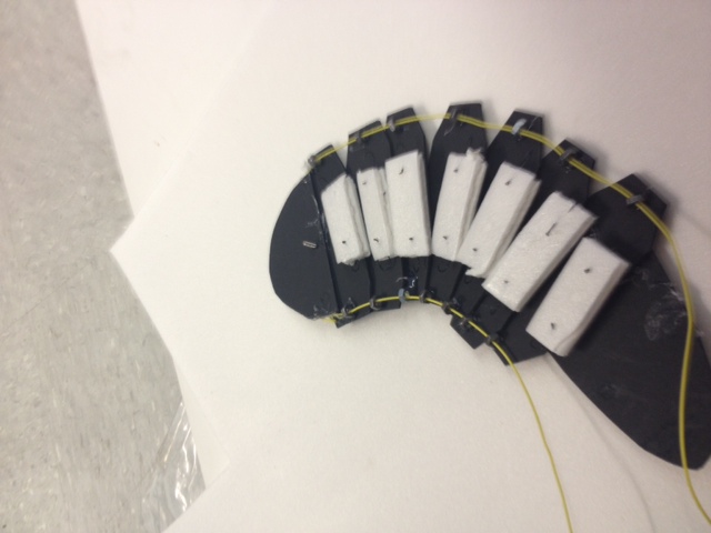
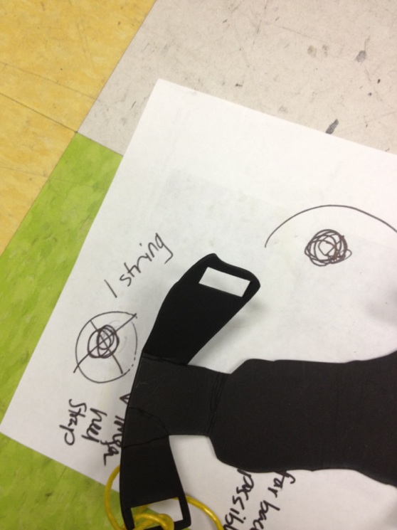
TLT to cut sheet piece for the glass climbing foot piece. Tested for good string placement.
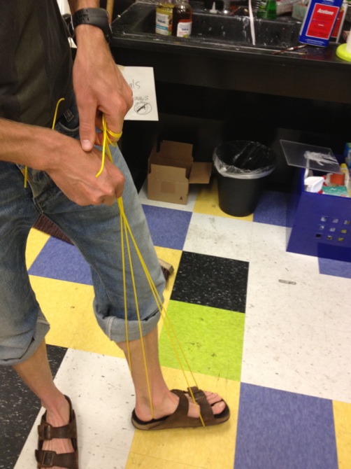
Realized it could simplify from four to three strings if the back string was placed at heel.
The front strings should be parallel to the wall. Toe tip needs to be widened for increased stability.
June 18 We set up summer accounts. I had a little trouble with typing in my password.
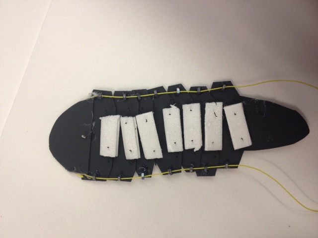
Discussed the glass climbing glove with Elliot and Tal. Talked about how force is dispersed in each finger paddle (even/uneven?), the spring mechanism, the benefits of splitting up the solid piece of sticky paper into smaller spring-loaded pieces that can adjust to rest on potentially uneven glass surfaces.
Went to a joint meeting with CS/haptics people to set summer goals for underwater grasping hand.
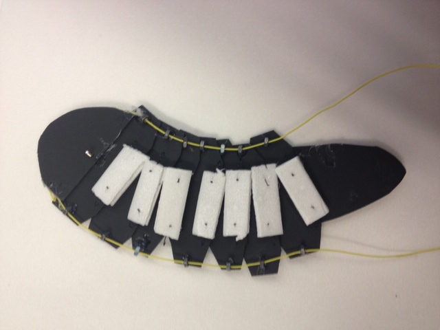
I explored ways to improve the glass climbing foot piece. Elliot helped me test the min amount that the foot should be kept away from the wall (and the min angle that the foot should rest in respect to the wall) so that the climber feels most balanced.
Made a Coreldraw model of the foot.