new web: http://bdml.stanford.edu/pmwiki
TWiki > Manufacturing Web>ManufacturingHome > ManufacturingEquipment>LevilCNC (01 Jun 2011, BarrettHeyneman)
| Contents: |
Levil Status
| User | Status | Estimated finish date/time |
|---|---|---|
Using the Levil
Turning on the Machine
- Make sure the machine is plugged in and is connected via USB to the computer. (USB Connection)
- Set the Emergency STOP button up by rotating it counter clockwise until it pops out. Know where this button is as it is the best way to quickly kill all power to the machine should something go wrong. (Emergency STOP)
- Turn on the compressed air for the tool changer and spindle cooling. (image)
- Flip the power switch, the light will turn on. (Power Switch)
- Open the Levil software by double clicking on the "LV10-MC-Shortcut" icon on the computer's desktop. (Levil Icon)
- The background of the GUI will be a bright green to show the machine is not connected to the computer. Click on the "Connect" button. The background should change to a teal (like this).
Working the Control Panel
General
When you open the software, there will be two windows that open, the (Control Panel) and the (Offsets Window). We'll talk about the Offsets Window later, for now let's start with the Control Panel (Shown Below):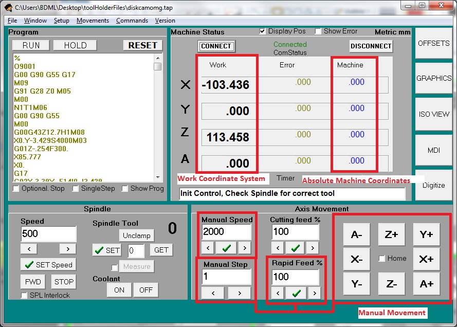 The Control Panel is split into four main sections. The upper right gives information about the machines positioning and current state. The highlighted box labeled "Absolute Machine Coordinates" displays the G53 position of the machine. The box labeled "Work Coordinate System" displays the current position of the machine in terms of the working coordinate system G54, G55, G56, G57, or G58, depending on what the user has specified. The lower right gives the user control over how and where the machine moves, the lower left controls the tooling and spindle, and the upper left is the program window where we can input GCode for the machine to run.
Stopping the Machine
- First off, to stop the machine where it is, I usually use the "RESET" option rather than using the emergency stop because it's quicker to get to when you're already using the control panel. To do this, either click on the ("RESET") button above the program window, or hit "F1" on the keyboard. This stops the machine and skips any code/commands it was given to execute before you reset it.
To Manually Move the Levil
- Find the Axis Movement section of the Control Panel:
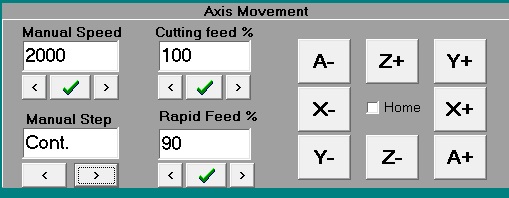
- Make sure the "Home" box is unchecked.
- Clicking on the X+/-, Y+/-, Z+/-, A+/- buttons will move the appropriate axis in the direction you specify by the amount specified in the "Manual Step" box at the rate in the "Manual Speed" box, scaled by the "Rapid Feed %" box.
- For continuos movement, make sure the "Rapid Feed %" box is set to 100, then increase the "Manual Step" until it reads "Cont".
Homing the Machine
The machine needs to be homed every time both the Levil and the computer have been turned off. To do this:- Check the Home box.
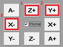
- Press the "Z+" button and wait for the machine to move to it's limit switch and then return to an index pulse. When it is done, the Status Bar in the "Machine Status" quadrant will read "End Home".
- Do the same thing for the "Y+" and "X-" buttons, in that order.
- Note, if you accidentally hit the wrong direction, the machine will crash provided you do nothing to stop it. You can just hit the "RESET" button or F1 to stop it.
Running A Program
- Running a program on the Levil is simple. From the Control Panel, simply click File > Open -- browse to your file which contains your GCode (this can be either a TAP file or any text file that contains GCode). Once the text is loaded into the Program Window, click "Run" in the program block.
- Alternately, you can write GCode directly into the program window and click "Run".
- NOTE: When I'm running a brand new program, I like to check the "Single Step" and "Show Prog" boxes directly below the Program Window. "Show Prog" opens another window that shows the current and future lines of code as the program runs. "Single Step" has the machine only run the code one line at a time, requiring the user to hit run after each executed line. I like to do this at least for the initial lines of any program (all the coordinate switching/tool changing/initial cuts). Once you feel comfortable that the program is running well, you can uncheck "Single Step" and/or close the Progress Window and the program will run normally.
Setting Up A New Coordinate System
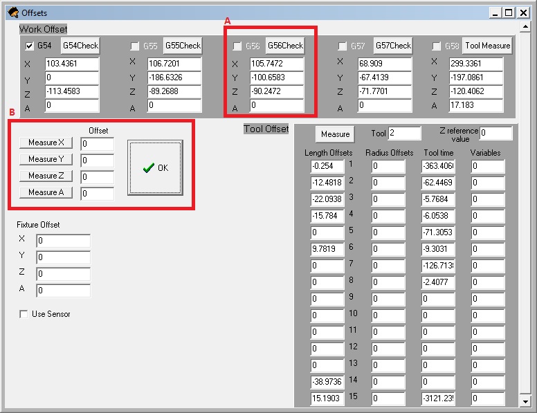
Normally we will just be using G55 as our work coordinate system for all SDM processes. However, if you would like to set up a new coordinate system (for example G56) follow these steps:- Go to the Offsets Window and click the "G56Check" button (in block A of the below image).
- With tool 1 in the spindle (see lower section on changing tools), manually move machine to the point you would like to set as the origin of G56.
- Click the "Measure X", wait, then "Measure Y", wait, then "Measure Z" buttons in block B of the below image. (NOTE: Make sure all the offsets boxes next to these buttons read "0")
- The work coordinate readouts in the Control Panel should all read "0.000" now.
Keyboard Shortcuts
Tooling
Table of Tools on Levil
Max cutting speeds have been left off. For approximate ranges, look at the HASSToolTable? on the wiki. If you have a good idea of what should go in here, fill in the chart.| Tool # | Tool Description | Tool Diameter (mm) |
Tool Reach (mm) |
Max Cutting Depth (mm) |
Max Cutting Speed, Wax (mm/min) |
Max Cutting Speed, Urethane (mm/min) |
|---|---|---|---|---|---|---|
| 1 | 1/4" Flat End Mill | 6.35 | ~30 | 3 | ||
| 2 | 1/4" Ball End Mill | 6.35 | ~35 | 3 | ||
| 3 | 1/8" Flat End Mill | 3.175 | ~19 | 1.5 | ||
| 4 | 1/8" Ball End Mill | 3.175 | ~40 | 1.5 | ||
| 5 | 1/16" Flat End Mill - Short | 1.5875 | ~5 | 0.5 | ||
| 6 | 1/16" Flat End Mill - Long | 1.5875 | 25 | 0.5 | ||
| 7 | 1/16" Ball End Mill | 1.5875 | 12 | 0.5 | ||
| 8 | ||||||
| 9 | ||||||
| 10 | ||||||
| 11 | ||||||
| 12 | ||||||
| 15 | Fly Cutter | ~40 |
Tool Basics
- In the Control Panel, you will find the Spindle Tool section:
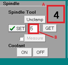
- The number in Box A displays what tool the machine thinks it has in the spindle. If this number is 0, then the machine assumes it has no tool in the spindle.
- To manually change this, enter the number of the tool you with the machine to assume it is using in Box B, then hit the "Set" button to the left. The number in Box A should change.
- Tool 15 will not be in the holder, as it is the fly cutter we will use or planing, and it is too large to fit. Whenever you're planing a block down, you will need to manually change to the fly cutter. The tool numbering scheme can be found "here".
Manually Changing Tools
- NOTE: To change tools, the compressed air must be hooked up to the machine!
Tools On the Tool Rack
- Make sure that the tool which is in the spindle matches the tool number in Box A of the above image, and that there is a vacancy in that spot on the tool rack.
- Assure that the tool you want to change to is also in the tool rack, in the correct position, and that the collet is clean of any debris.
- Enter the desired tool number in Box B of the above image and click the "Get" button.
Tools Not On the Rack
- Grab the tool in the spindle with one hand.
- Click and hold the "Unclamp" button in the Spindle Tool Section until the tool drops out of the spindle.
- Clean the tool holder for the new tool.
- Hold the new tool in its holder inside the spindle.
- Click the "Clamp" button. The tool will be pulled up into the spindle.
- Make sure the tool holder is tightened around the new tool.
Setting Tool Height Offsets
Reference Tool 1
- NOTE: The Levil uses the middle of the cutting end of tool 1 as its zero reference for all tool height offsets. As such, tool 1 should not be changed, and if it needs to be, all other tool height offsets need to be reset.
- Mount Tool 1 in the spindle.
- Place electronic tool setter on the reference surface and manually move the tool near the tool setter (see below image).
- Electrically connect the bottom of the tool setter with the spindle (unfortunately the Levil is not electrically connected throughout, so we must take this extra step (below image).
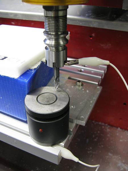
- Very carefully, manually move the tool until it just barely causes the light on the setter to turn on (this usually takes a little back and forth at various step sizes). ("image")
- In the Offsets Window, select the G58 "Tool Measure" ("Block A") coordinate system, and click "Measure X", "Measure Y", and "Measure Z" (in "Block D", remember to make sure the "Offset" box reads "0") , waiting for the window to refresh between each one.
- Now, in the "Tool" box of "Block B", put "1".
- Hit the "Measure" button in Block B. The "Length Offsets" box for Tool 1 should now read "0".
Other Tools
- Once Tool 1 is all set up as described above, you can now set the offsets for the other tools that will be used. Say you want to set the offset for tool 4, you would:
- Mount Tool 4 in the spindle.
- Place electronic tool setter on the reference surface and manually move the tool near the tool setter (see below image).
- Electrically connect the bottom of the tool setter with the spindle (unfortunately the Levil is not electrically connected throughout, so we must take this extra step (below image).
- Very carefully, manually move the tool until it just barely causes the light on the setter to turn on (this usually takes a little back and forth at various step sizes). ("image")
- In the Offsets Window, select the G58 "Tool Measure" ("Block A") coordinate system.
- Now, in the "Tool" box of "Block B", put "4".
- Hit the "Measure" button in Block B. The "Length Offsets" box for Tool 4 should have changed.
Planing
- The easiest way to plane a wax block down on the Levil is to download the planing code generator file for Matlab. Open this in Matlab and run the function "planingGenerator.m" by calling planingGenerator(start_height, end_height) in the command window. The start height and end height should be values in the G55 coordinate system.
- This script will output a text file called planingProgram.txt into the same file as the .m files.
- Open this file in the Levil Control Panel as normal, manually place the planing tool (Tool 15) into the spindle and set it as the current spindle tool BEFORE running the program.
- Run the program.
Mounting a wax block
Cleaning
Machine Setup
- There are various aspects regarding the setup of the Levil, but the following are the ones that are of general interest for everyday use of the machine:
- The Levil needs to be hooked up to compressed air for the tool changer to work and some type of coolant (air for wax) and machining coolant for metals. "Here" is a picture of where to hook all of this up. The compressed air needs to be ~90psi .
- Various settings including tool rack positioning, blah blah blah , and home directory can be changed in the "Parameters" window (from the Control Panel go Setup > Parameters). In order to change anything in this window you will need to enter the password '1588' into the appropriate box in the window.
Tech Support
- I have needed tech support for various problems with this machine. For assistance, either email me (Marcus Albonico, albonico@stanford.edu) or contact:
Ruben Leon
Phone: 407-542-3971 (fastest way to get help)
Skype: leviltec (best for software problems)
Email: ruben@levil.com (best for small things)
Mon-Fri 9am-6pm, EASTERN TIME
- If you find a software bug, note it in the section below, then email Levil with the problem, they usually just send an updated version of the software (fairly quickly). Once you get the new software, verify the problem is fixed and remove it from the Bug List.
Levil Files
| Filename | Description |
|---|---|
| bdml.zip | BDML Pro/Engineer Setup Files |
| Levil.zip | This folder contains all files needed to run the Levil including version 5.12 of the LV10-MC software and various user manuals. |
| WL400_User_Guide_Version_5.0.pdf | Versions 5.0 User Manual |
| Planing.zip | Planing Matlab Scripts and Program Files |
Setting Up ProE? for the Levil
1 Save and extract the necessary BDML Pro/Engineer Setup Files from above.- In Windows explorer, navigate to the C:\ drive. Check to see if there is a directory called "C:\BDML". Clear out everything in this directory(Pro/Engineer has to be closed to be able to do this).
- Inside the .zip file, move everything in the BDML directory into C:\BDML. Everything Pro/Engineer needs is contained within this directory.
- Finally, you need to modify the Pro/Engineer Shortcut in the start menu to point to "C:\BDML".
- Open up the start menu, navigate to the Pro/Engineer icon.
- Right click on the icon and open up the properties.
- In the "Start In" field, type C:\BDML (image)
Bug List
There are multiple ways of accomplishing the same goal when it comes to the Levil. All the procedures that I have explained above work well for me and you should not encounter any bugs if you follow them as I have written them out. That being said, there has been no shortness of bugs when working with the Levil, so if you find one, write it down here and take some sort of action towards resolving it (e.g. write me, MarcusAlbonico? , call/write/skype Levil, etc).Ideas, requests, problems regarding TWiki? Send feedback