Category: SummerBlogs
Resources:
- Tutorials - Arduino/Onshape
- Heather: Final SURI Poster | Passive Left-Ventricular Phantom with Soft Wireless Resistance Sensor
- Olivia: Final SURI Poster | Origami Heart: Benchtop Simulation of Left-Ventricular Motion
- SURI Meeting Presentation Slides
Week 10
Friday, 8/26/22: We had our final SURI poster session today!
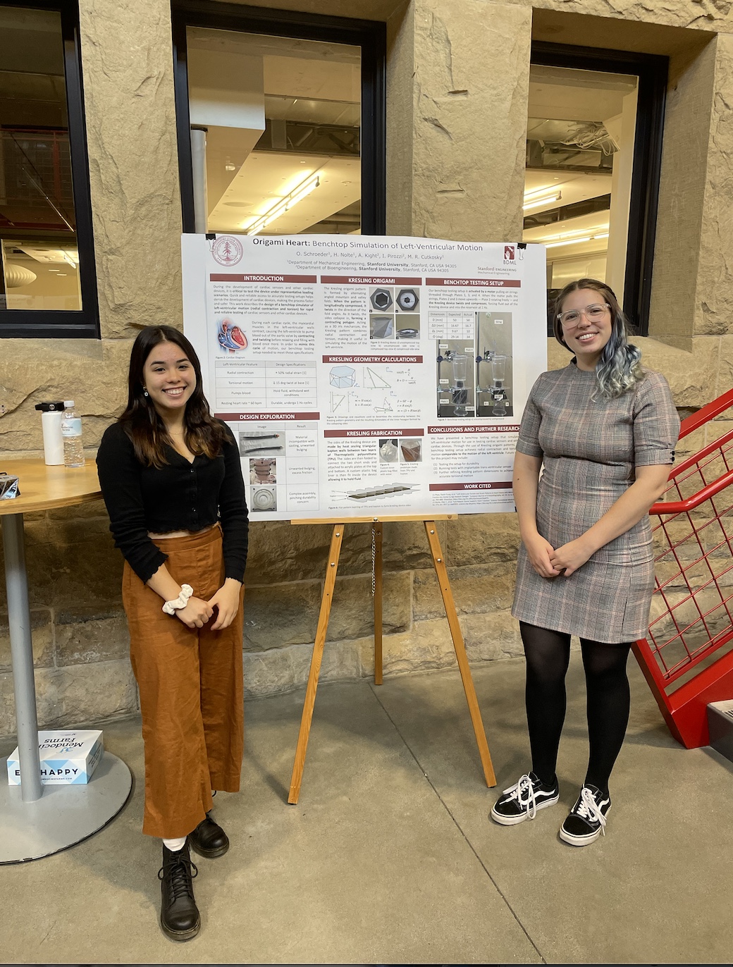 | 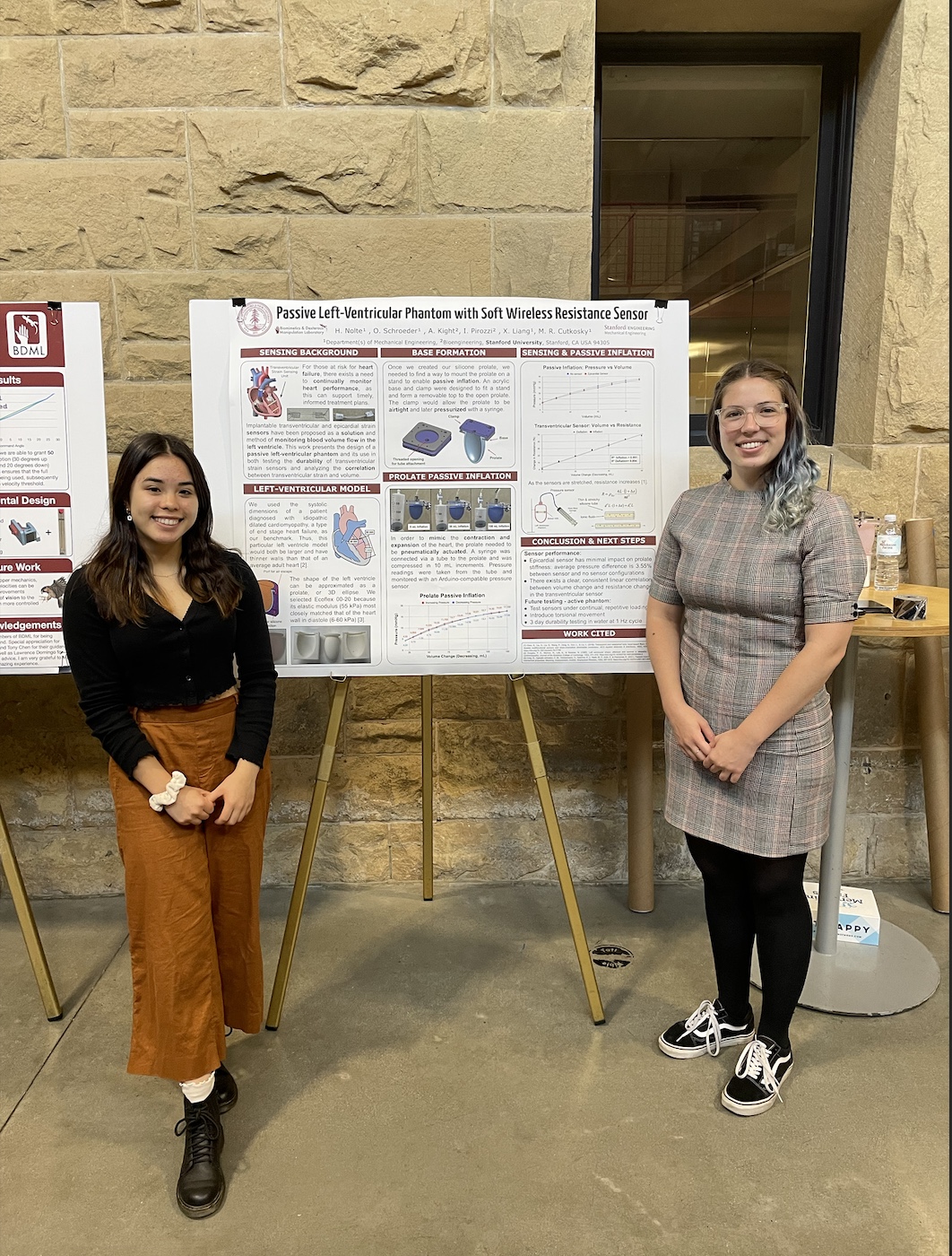 |
| Olivia's poster | Heather's poster |
Thursday, 8/25/22: I made some hydrogel solution without any salt in the morning. The gel solidified very quickly, but it ended up being pretty breakable and not as elastic as hoped. I also started another sensor to be soaked in water and monitored the resistance over time.
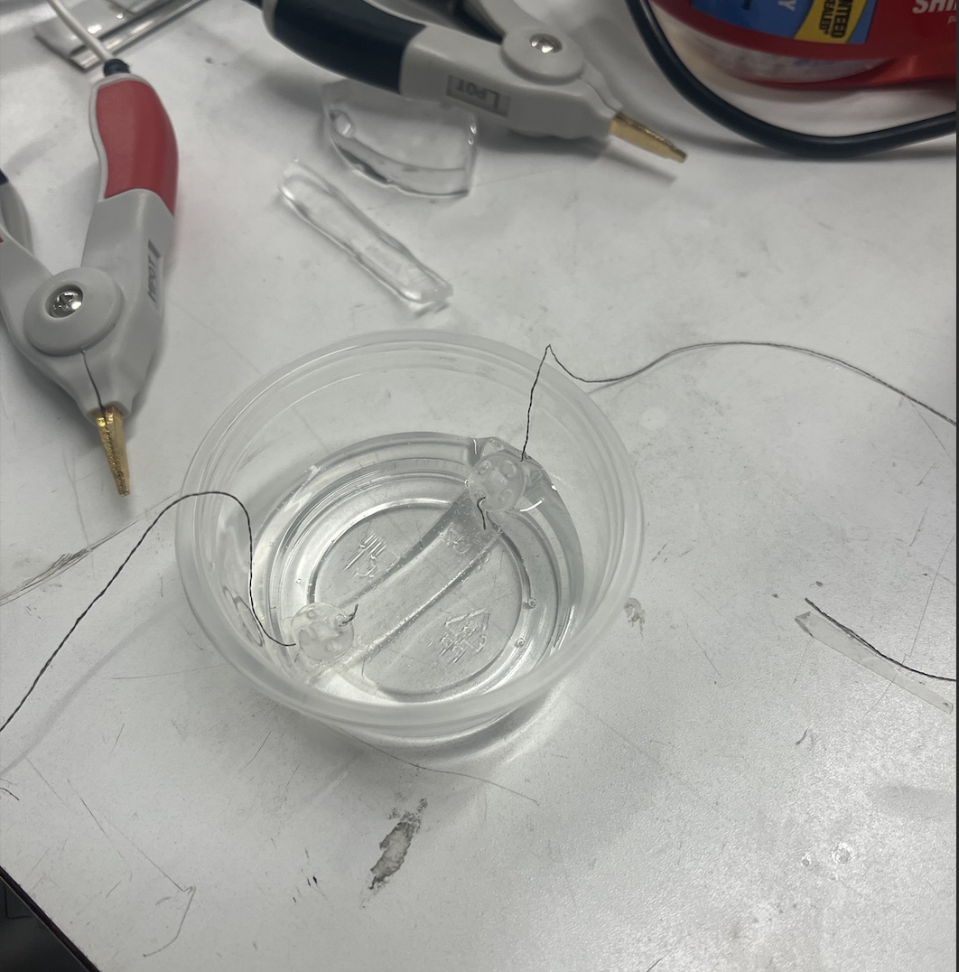
hydrogel sensor in water
Wednesday, 8/24/22: I made some more sensors out of hydrogel and tested how the resistance changed over time as they were soaking in water. The resistance initially decreased in the water, but after half an hour, the resistance shot up and the sensors swelled. It was challenging to create the sensors because the hydrogel is fairly breakable and not as elastic as the silicone we were working with originally. The sensors also tended to break at stress points where we sewed in the button ends that would allow the sensors to clasp into points on the inside of the left ventricular phantoms.
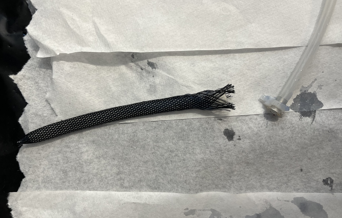
We also had our team meeting with the cardiac corner today, and we learned more about potential wireless sensing options from Xinyi. In the afternoon, I tried to fit some of the hydrogel in a stretchy silicone tube. This was pretty challenging because the hydrogel had to be cut into very thin strips, making it even more breakable. I used super glue to fix a conductive thread to either end of the thin strips of hydrogel, and fished the sensor through the tube using the conductive thread. Most of my attempted ended in a broken piece of hydrogel, though I did manage to get one working. In the long run, however, it would be difficult to get hydrogel inside the smaller, stretchier silicone tubes that we need.
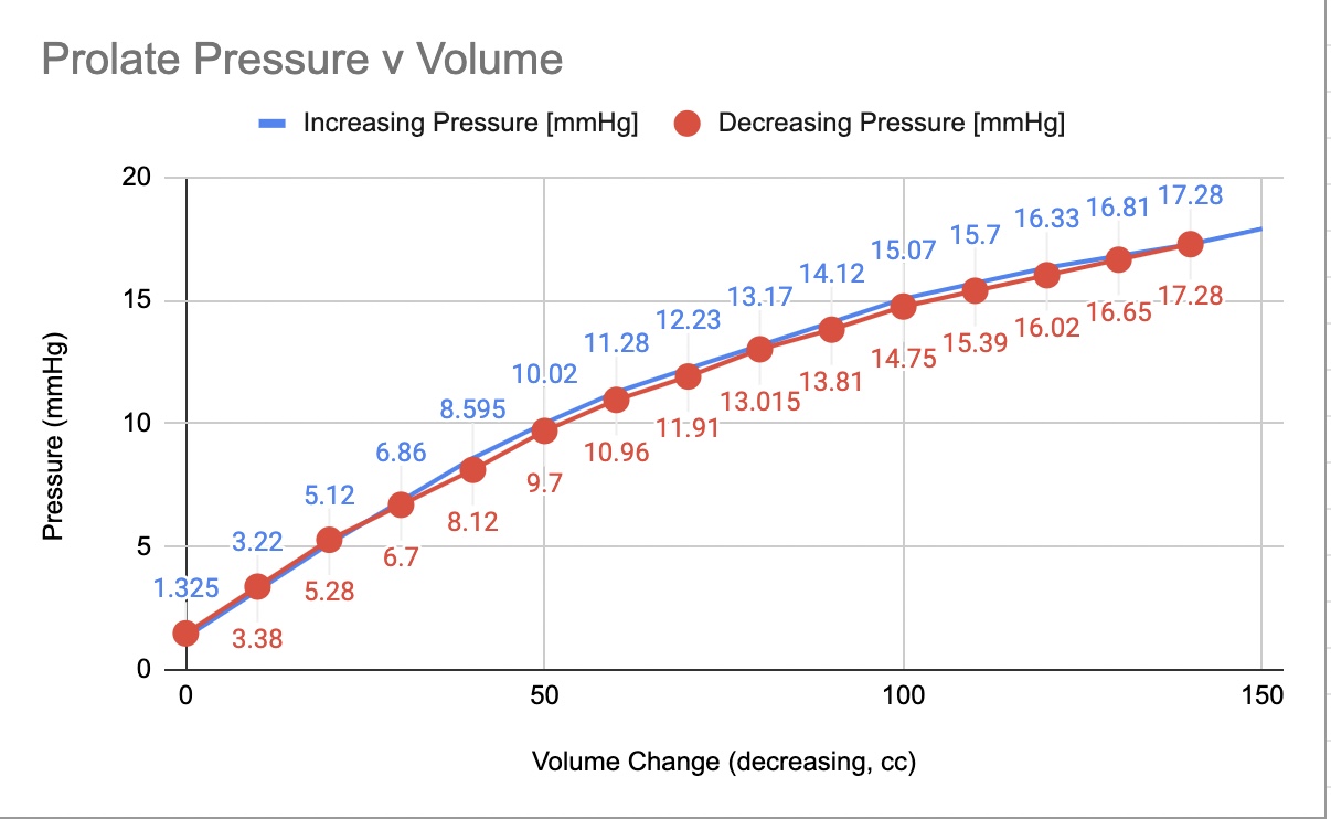
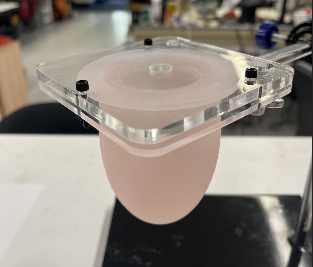
Tuesday, 8/23/22: I attached a sensor inside the passive prolate today. The sensor was made from a conductive hydrogel and was very delicate. When I assembled the wrapped prolate and new sensor, the prolate initially leaked when pressure was added. I clamped down the plate by tightening and readjusting the screws, making sure that the prolate was air tight before running pressure tests. Olivia and I measured how the resistance changed with the increased pressure in the stiffer passive prolate.
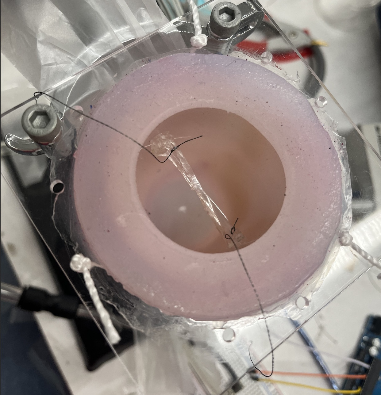 | 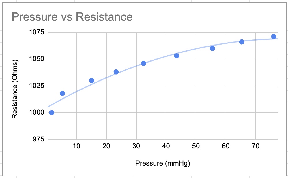 |
| Sensor inside passive phantom | Pressure volume relationship |
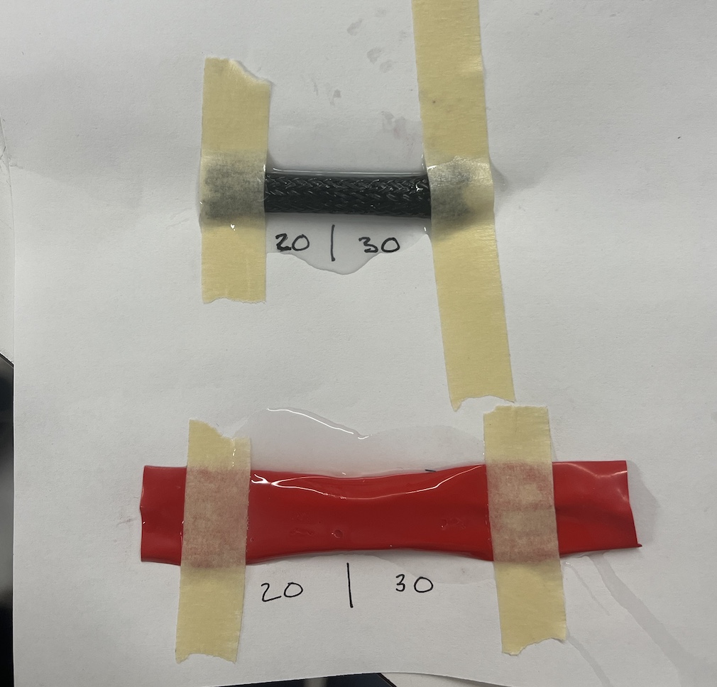
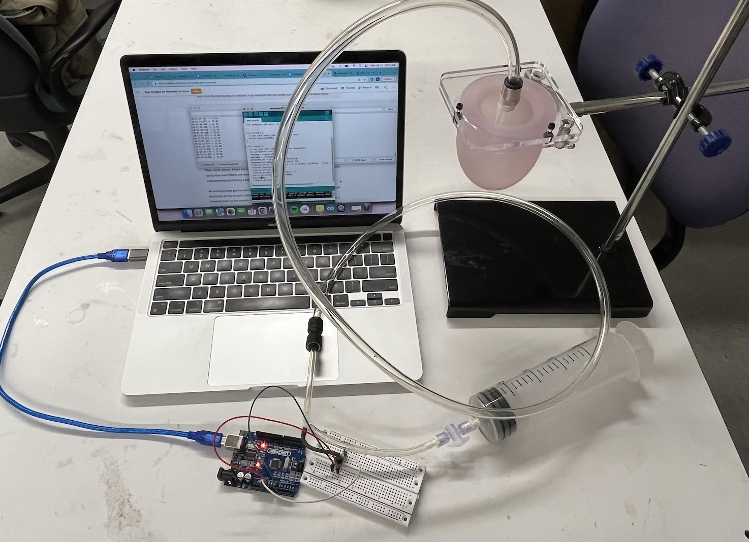
Monday, 8/22/22: We had our weekly SURI meeting today. After listening to the last 4 presentations within our cohort, we made plans for the final poster session this Friday. I also worked on setting up a second stand with our original silicone passive phantom. Ali wants to test how a stiffer phantom + high pressure inside the prolate will impact a transventricular sensor. There are some publications that have mentioned that resistance tends to decrease when the sensors have been placed under higher pressures (eg in greater depths of water.) To create a stiffer phantom, I wrapped the prolate in BOPP plastic, which does not stretch. This would prevent the prolate from expanding (or at least mostly expanding.) I found it hard to completely hold the phantom in place while adding pressure as it kept expanding downwards. After recalibrating our pressure sensor to an arduino board, I made some PV charts documenting the change:
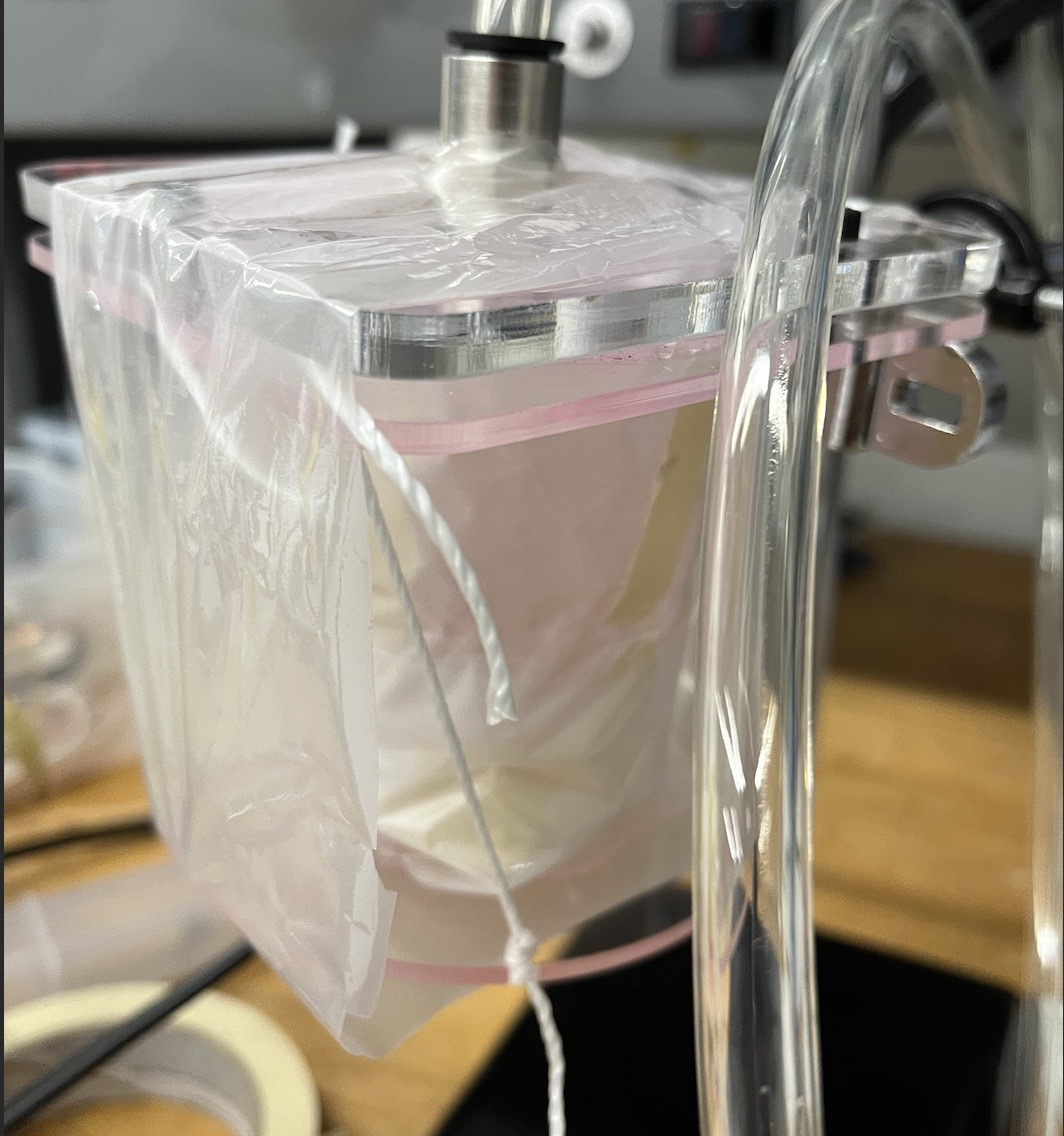 | 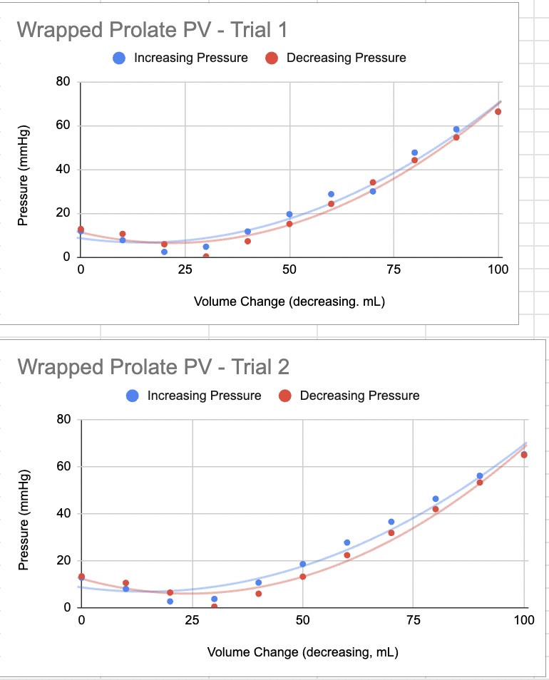 |
| Phantom wrapped in BOPP | PV Charts |
Week 9
Friday, 8/19/22: I submitted my final draft of my poster and helped set up for the barbecue in the morning.
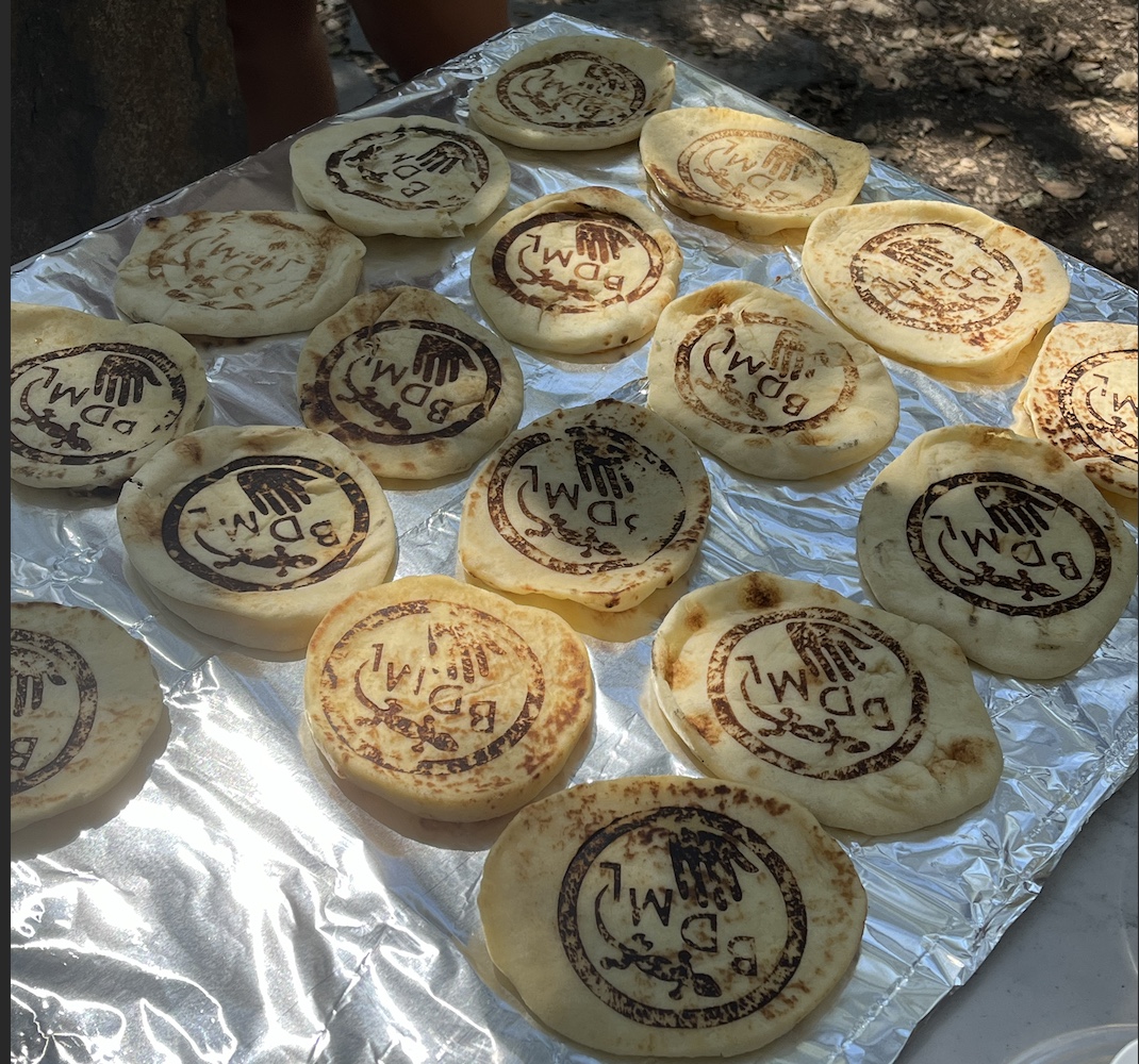
naan branded with BDML logo!
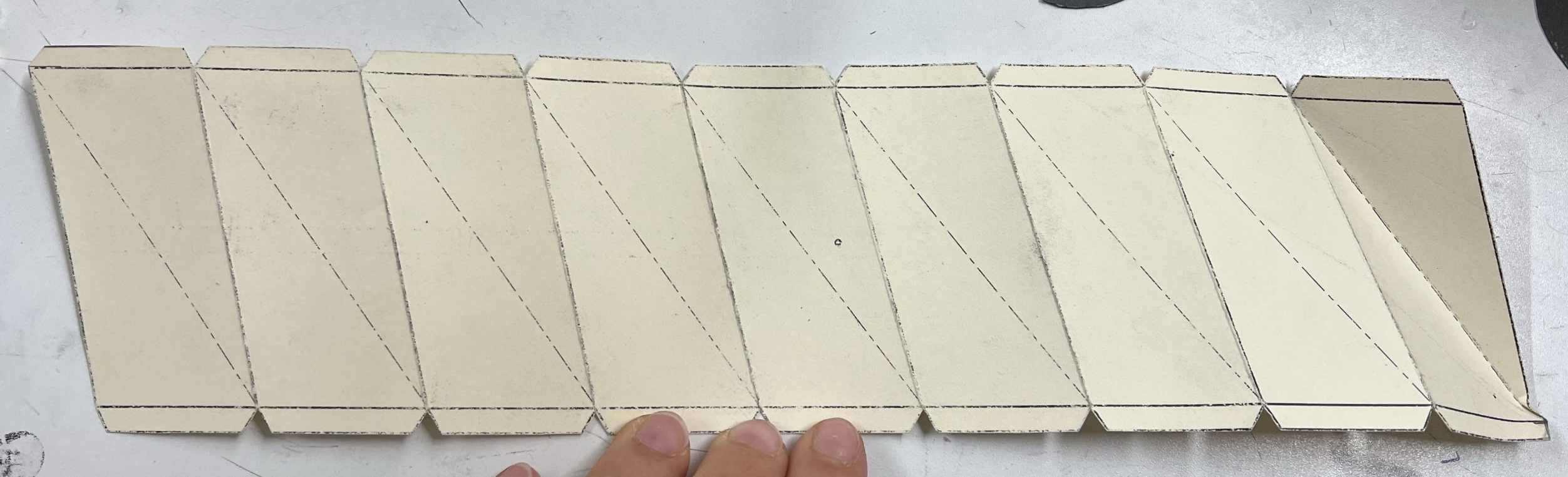
In the afternoon, I finished up the kresling tutorial.
 |  |
 |  |
Thursday, 8/18/22: Olivia worked on writing up a Kresling tutorial, so I followed it and started working on a second, backup Kresling prototype using the impulse sealer.
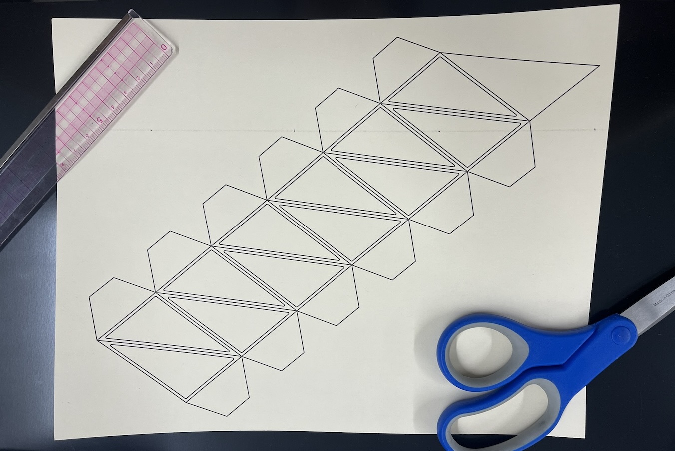 | 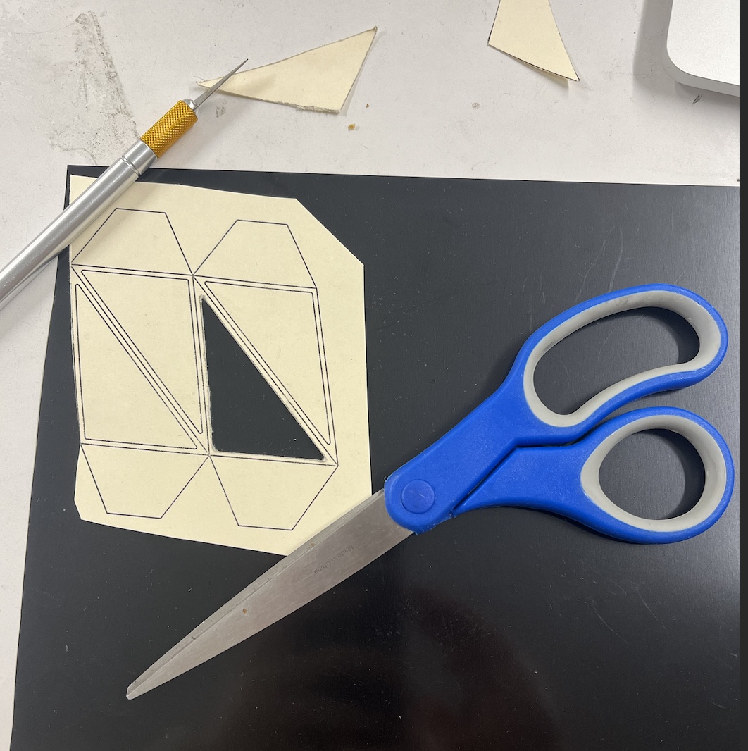 |
| kresling pattern | kresling stencil |
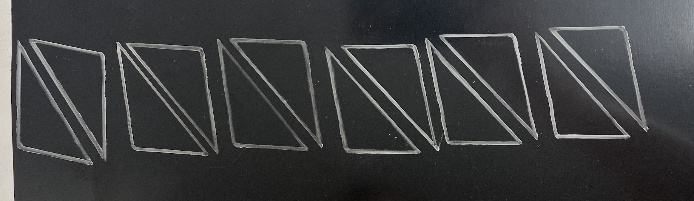
design traced onto kapton
We also had our poster review session today, so I spent the afternoon revising my poster before the final submission. After the review session, the lab worked on making skewers for the Friday barbecue hosted by BDML.
Tuesday - Wednesday, 8/16/22 - 8/17/22: I spent a lot of time on my poster over Tuesday and Wednesday, and came into the lab to take some photos to better describe our process for the passive phantom setup. The Kresling setup was also operating on a 1/2 Hz cycle, and I sped that up to 1 Hz and got through some adjustments to make that possible. Olivia and I also measured the inner diameter of the Kresling model to make sure that it was compressing in the right amounts.
Monday, 8/15/22: Olivia and I presented our research at the SURI lunch meeting today. We spent the morning practicing our presentation and calibrating our kresling to the newer, stronger motor that we ordered on Friday. We added water to the setup and found that the original fishing line stretched when enough weight was added, so we switched it out for a stiffer string that also minimized friction. We swapped out the bar that we were originally using for a threaded rod, fixing nuts on the rod to secure our pulley. After making our adjustments to the kresling testing base, I spent the rest of the afternoon on my final SURI poster.
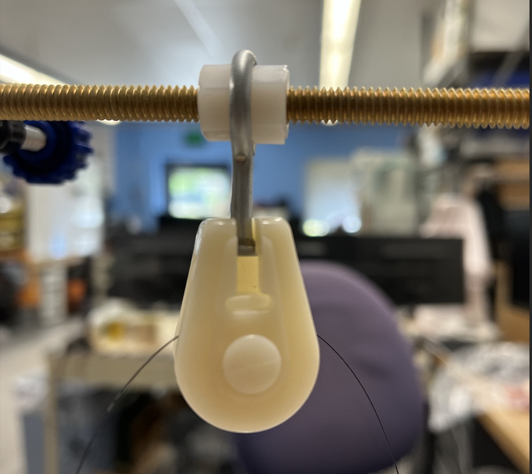
new pulley attachment
Week 8
Friday, 8/12/22: We finished our new Kresling prototype with an acrylic plate, so I was able to attach it to the motor and pulley setup today. I fit it to the dimensions Olivia found for the Kresling, and played around with arduino until we got the right amount of vertical compression. I also added water to the prototype, which placed some strain on the motor. We decided to order a stronger set of new motors to address any strain + add a safety factor in when filling the system with water. There was some stretch to the fishing line as well, so I'll look for some similarly frictionless (but stronger) string to use for the pulley. The servo we used ultimately was strong enough to pull up the water, but when I stopped it at the top, the servo didn't lock in place and slid back down, resulting in slow shifts when running the system over time. Hopefully a stronger servo will address these problems.
Kresling filled with water
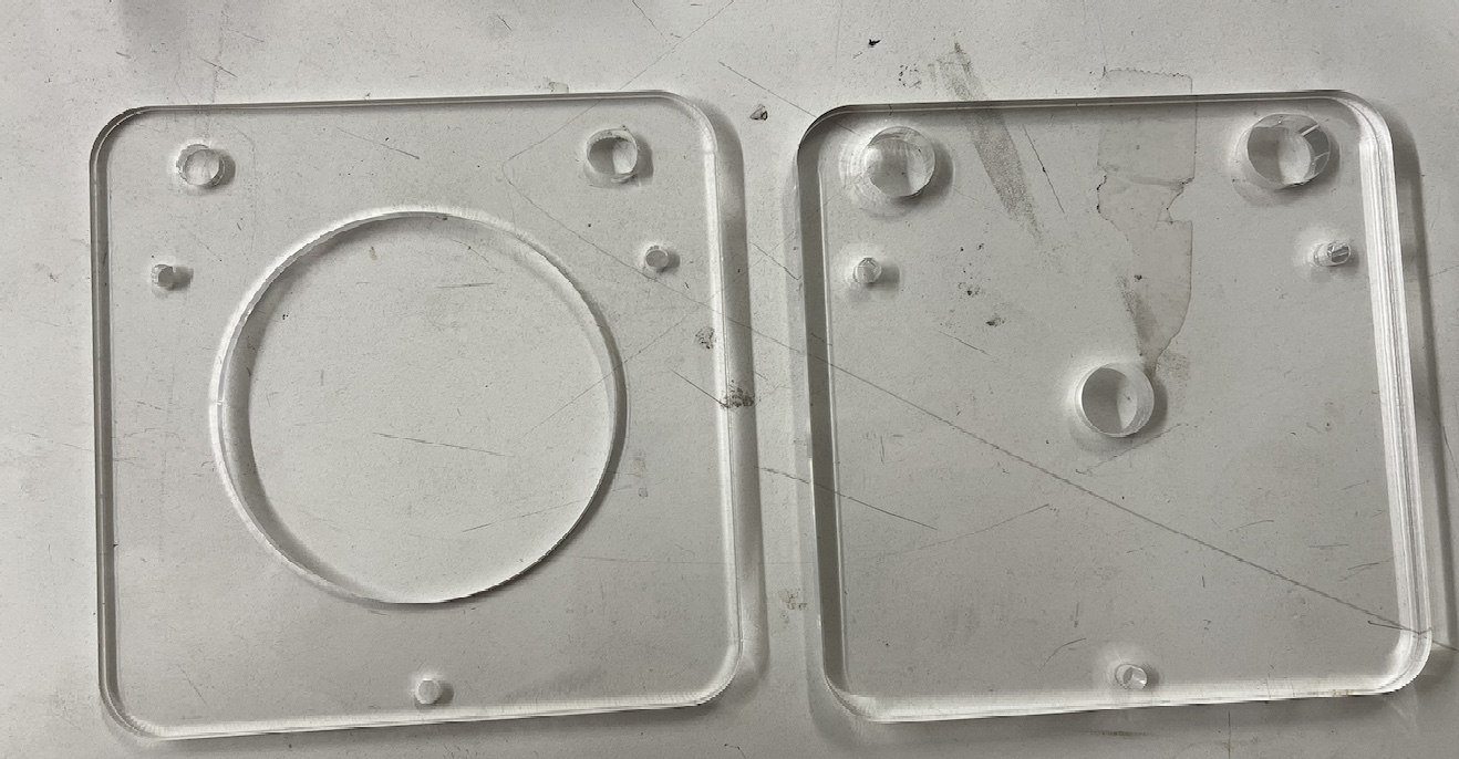
Wednesday - Thursday, 8/10/22 - 8/11/22: Olivia and I worked on our upcoming SURI presentation powerpoint today. I also started assembling the laser cut acrylic plates that we finished Tuesday. I found an approximate range for the diameter of the aortic valve and found a tube that fit the specifications. After sawing it to size, I connected the tube to a clear plastic cup that will serve as a "tank" for the fluid that we'll pump in and out of the heart. I also created a stand for the cup and tube to sit on while attached to the top plate of the Kresling to keep everything in place.
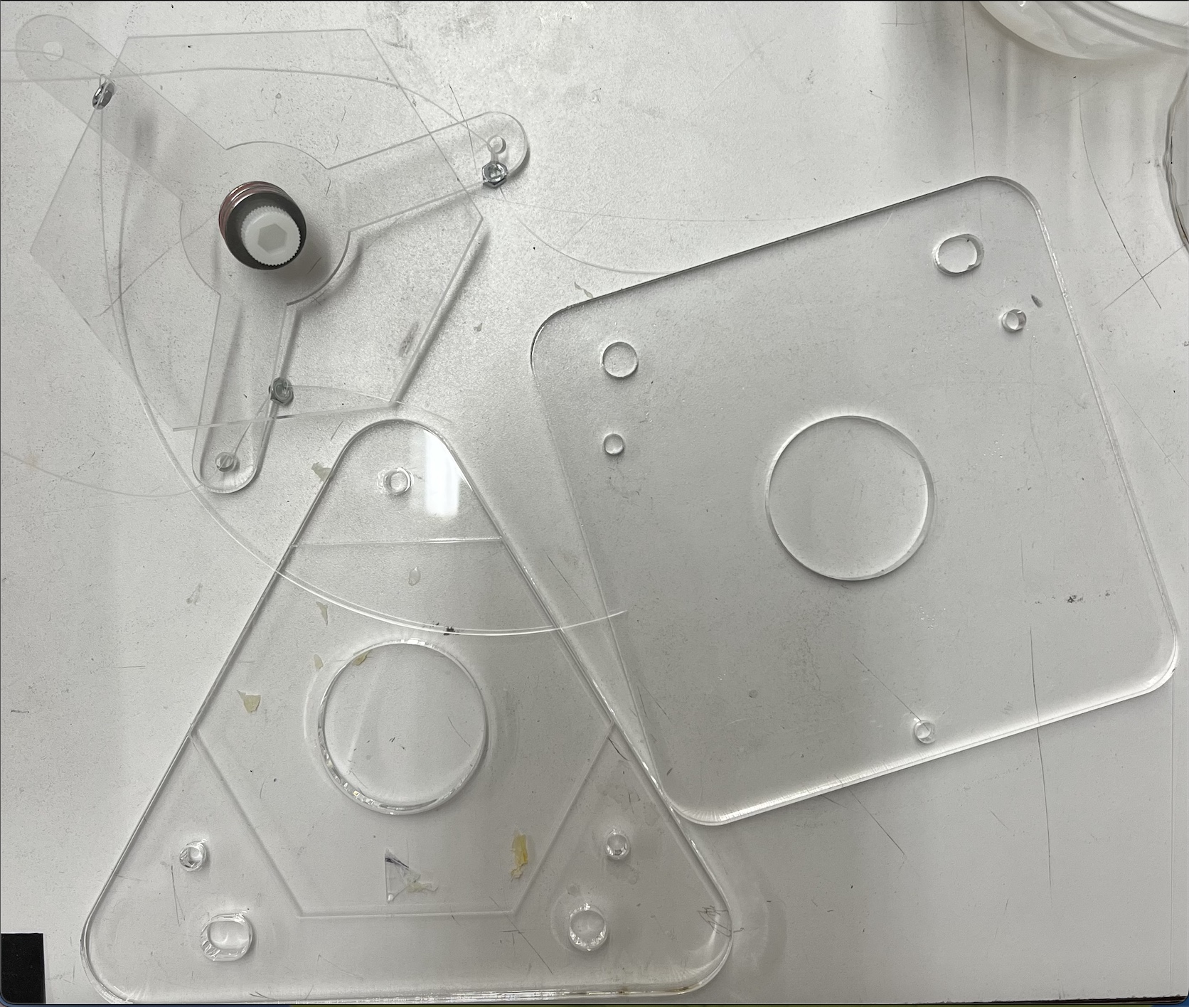 | 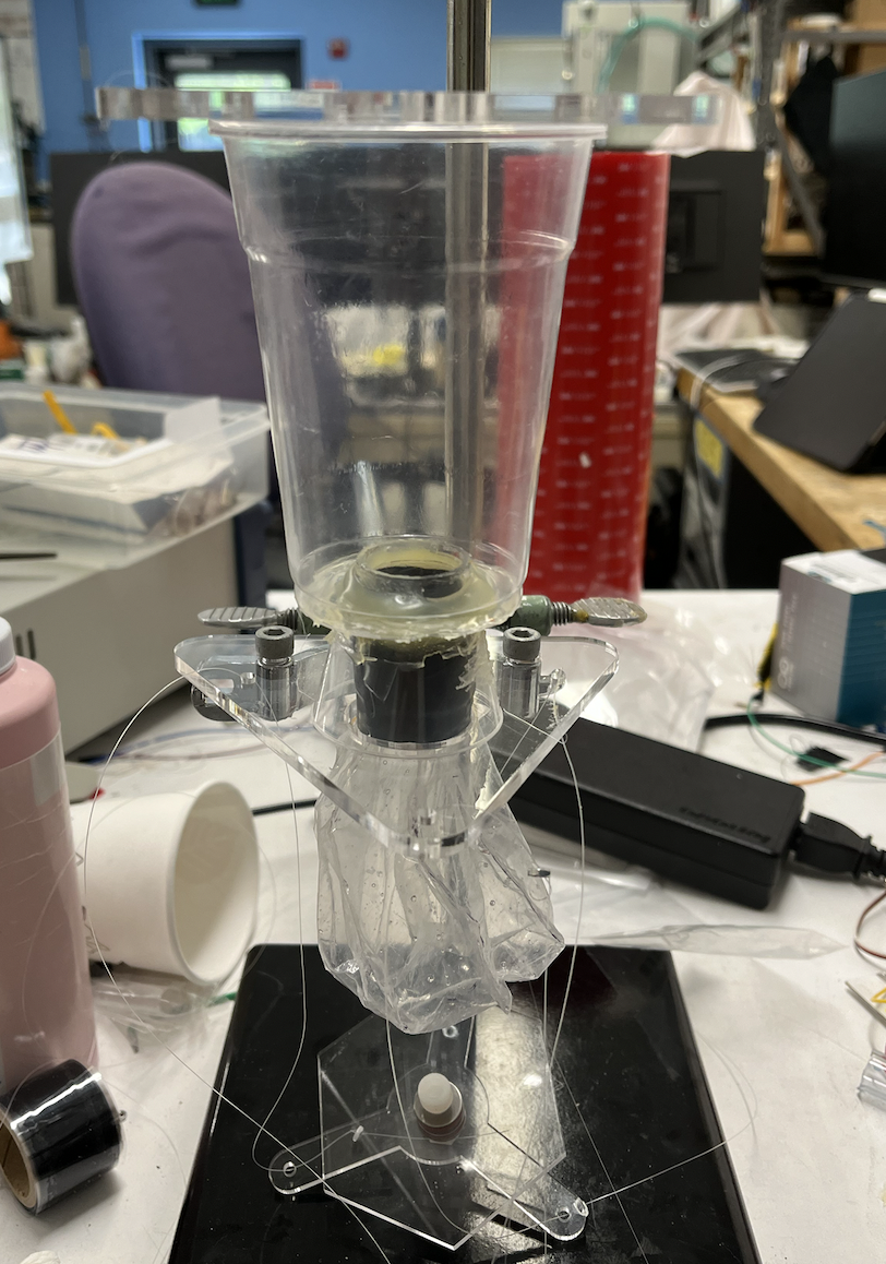 |
| laser cut acrylic plates | cup and base assembly |
Tuesday, 8/9/22: I added a second servo motor today in hopes of synching two together and using their combined strength to lift/compress the kresling prototype. However, unless the two servos were somehow mechanically connected, it would be difficult to get them to be perfectly in time as they would slowly become out of synch over time. I was concerned that the original single motor would not be strong enough to lift everything, as it began to struggle and get choppier as I added resistance to the system. However, I found that my problem was that the motor itself moved choppily even without any stress being placed on it. After I switched out the faulty motor for a new one, the plate moved a lot more smoothly.
servos out of synch
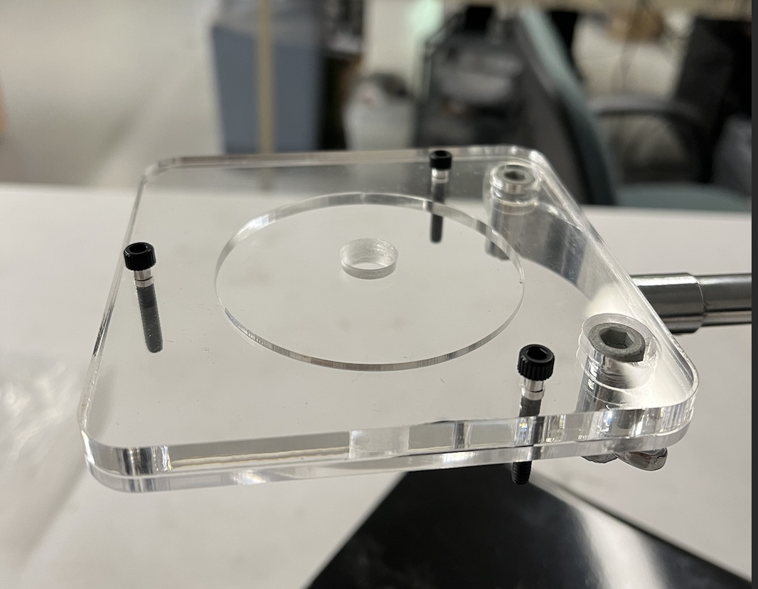
Olivia and I also fleshed out how to attach the kresling to the pulley system using by acrylic as the top and bottom plates of the prototype. We settled on adding another clamp to the stand that will hold the motors, leaving space for a small water tank/cup that will sit on the original stand and act as the top of the kresling. The bottom kresling plate will be attached to a thrust bearing, allowing it to spin relative to the moving plate that will be attached to the servo motors. I also added a rod with a plastic pulley attached to it that would support the string and help the plate be pulled up evenly.
 | 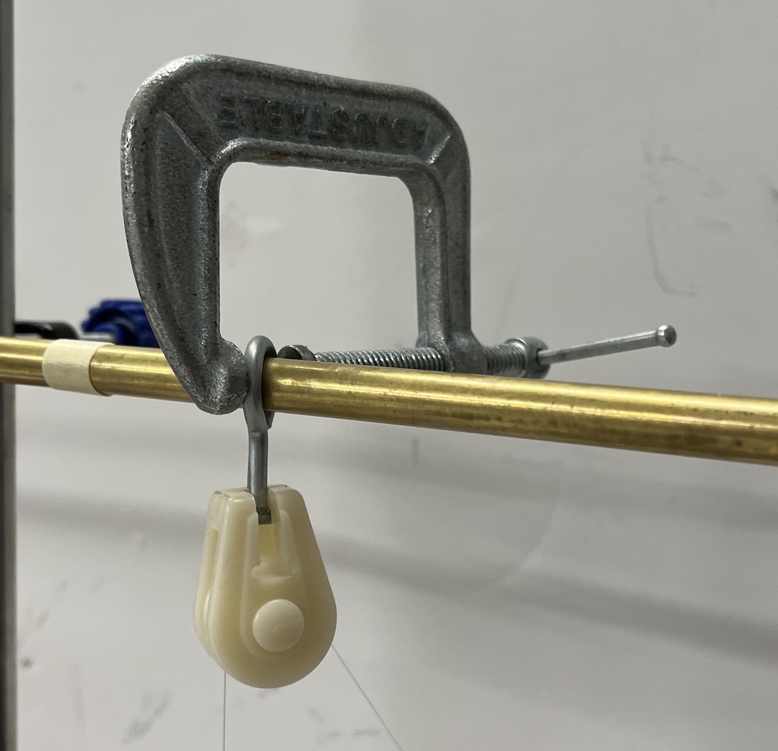 |
| base assembly in Onshape | plastic pulley clamped to rod |
Monday, 8/8/22: I focused on getting a servo motor to lift the bottom plate of the Kresling design in order to actuate it. I found a big servo motor and used a power source to provide a breadboard with 6v to power the motor. Using an arduino uno board, I was able to select specific locations for the motor to turn to. I attached the motor to the top plate of the base, and sized some strings to accommodate the Kresling module. In order to get the plate to lift up straight, I had to use a rod to act as a pulley that was attached to the rotating servo. By positioning the rod directly above the plate I wanted to lift, I was able to get the motion that I wanted. The servo was strong enough to lift both the plate and actuate the Kresling, but I believe that adding water will be an additional challenge that will require a stronger (or multiple) servos.
servo motor in action with pulley
Week 7
Friday, 8/5/22: We had BDML's weekly lab meeting today. After presentations about gecko materials and the tadpole project, we went to the MERL barbecue. I met virtually with Olivia about Kresling dimensions and we debriefed Ileana on our linear actuator ideas. In the afternoon, I searched for a linear actuator that would meet our specifications (and one that would ship in time as our deadlines for SURI are coming up.) I had a few options to sort through of varying speeds, lengths, and strengths. I settled on a 2" rod that moved at a max speed of 50 mm/s. This would provide us with the 1 hz cycle that we'd want to test the sensors. One problem I ran into was that these actuators cannot be run continuously at max speed for long periods of time due to overheating problems. Our best options still had a 10% duty cycle, meaning that they could only run for a few minutes at a time before having to be shut off. Ali and I met with Rachel, who suggested we look into servos again. We settled on trying the servos we had already around the lab. The linear actuator idea ended up being more complicated than hoped for, so if we can make servos work, that's definitely the way to go.
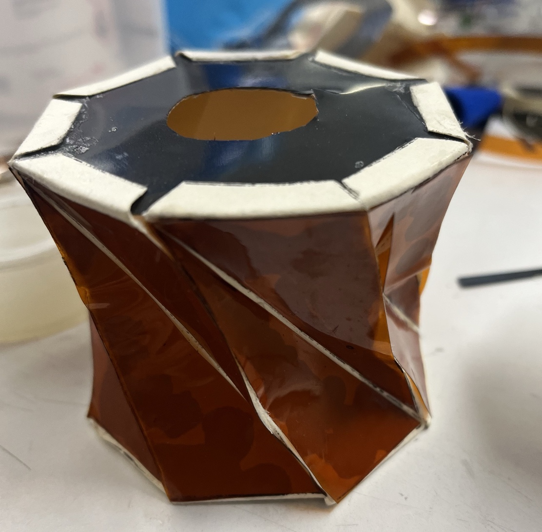
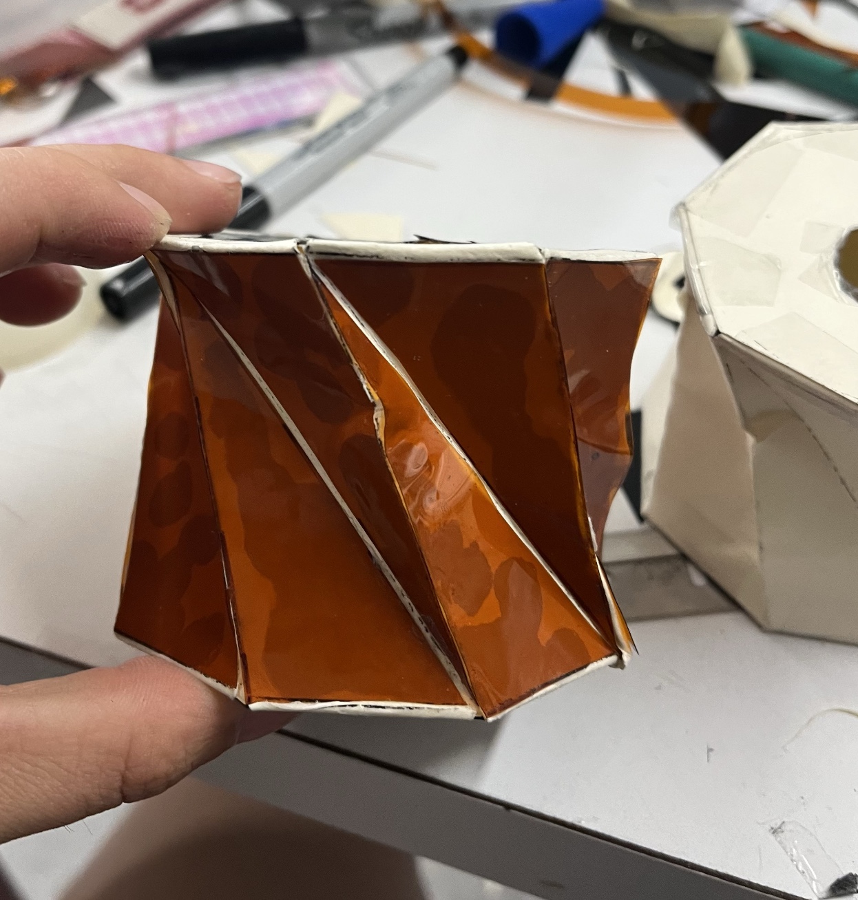
Thursday, 8/4/22:
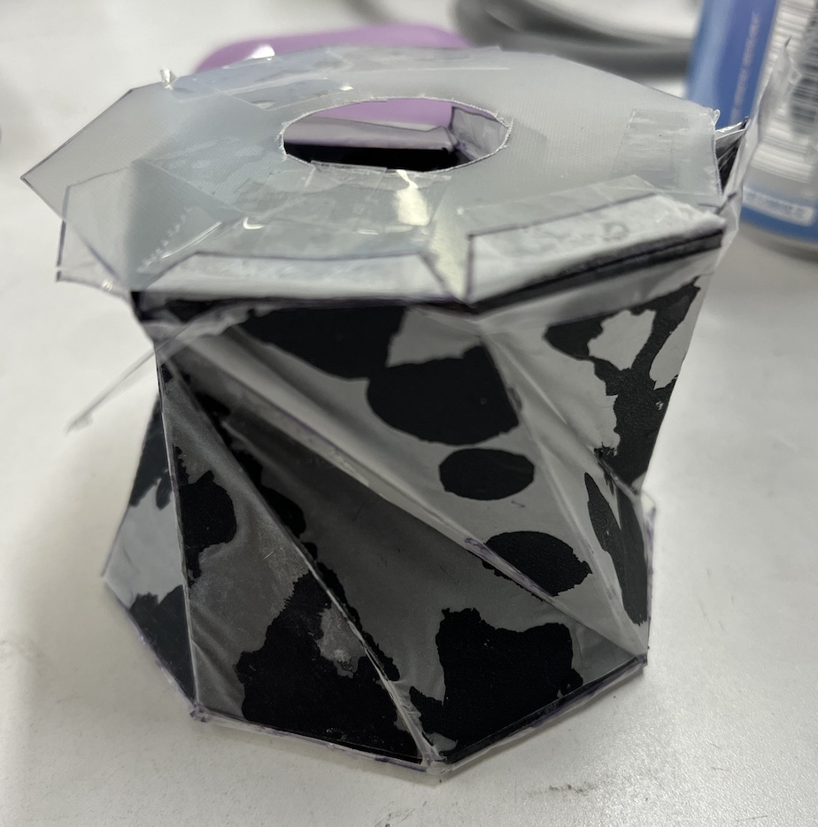
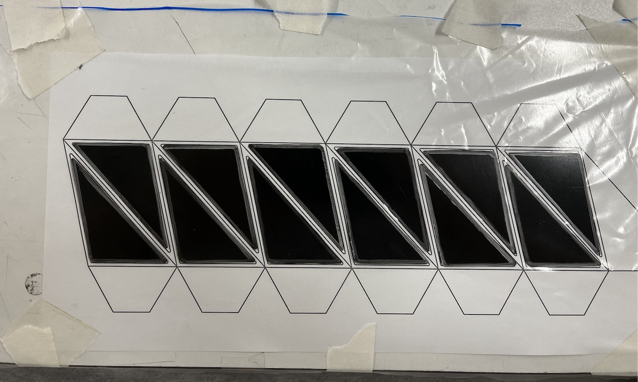
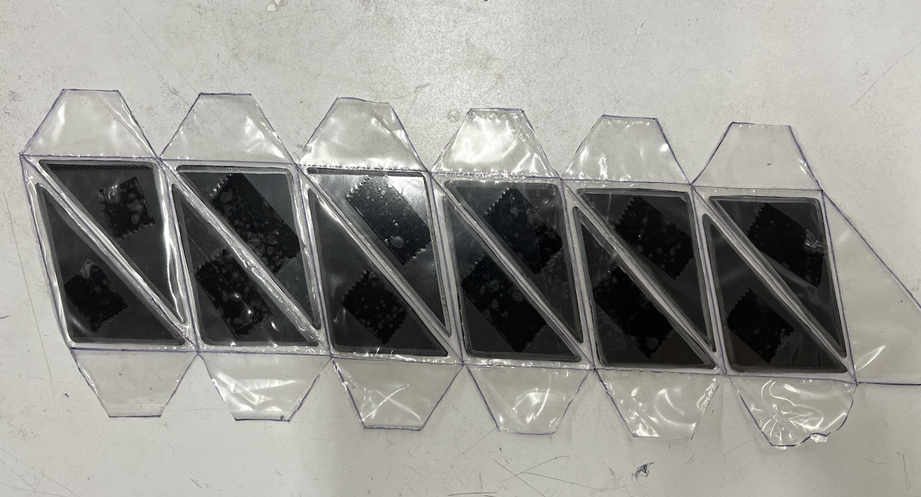
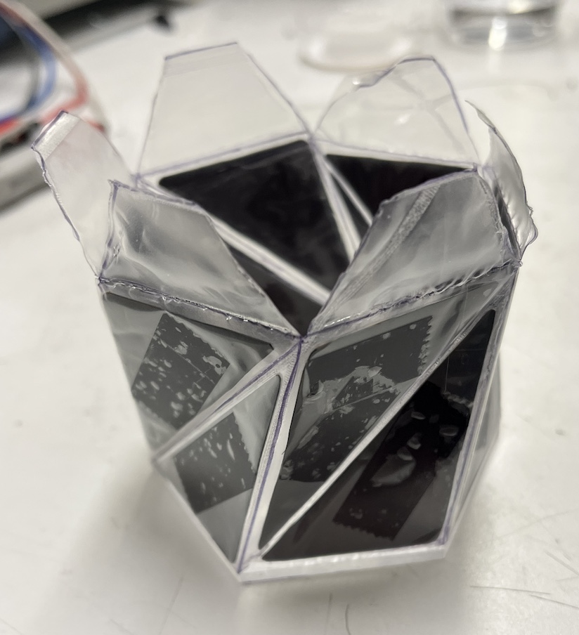
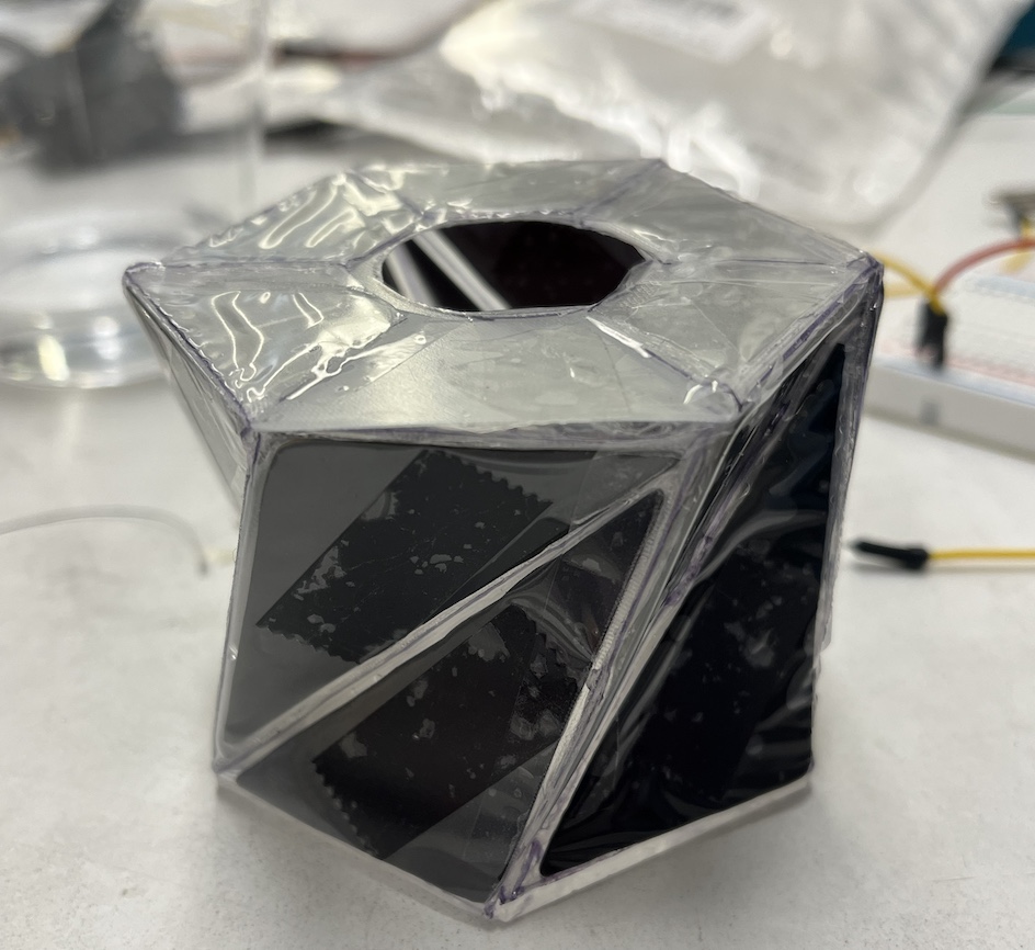
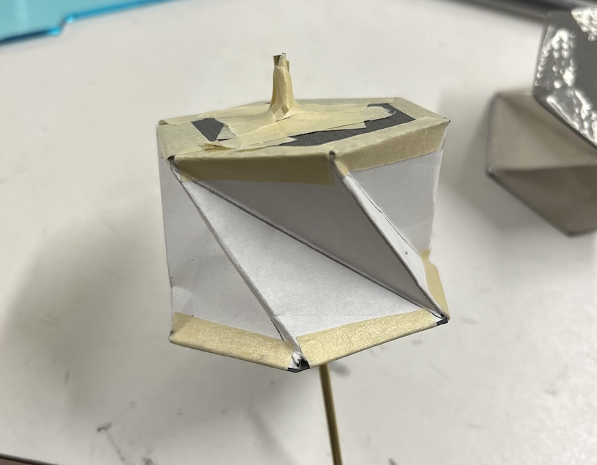
Octagonal Kresling with kapton and BOPP
I worked on making a plastic waterproof Kresling today using Kapton for the triangular sections and BOPP as the soft bendable material between. I used super glue to attach the triangle pieces to a flat section of BOPP that I traced my desired pattern onto. I attempted to create an 8 sided Kresling, but the super glue proved very difficult to work with as the Kapton bonded instantly to the BOPP. I had to place each section very carefully, and my fingers frequently got stuck to the BOPP.
Wednesday, 8/3/22: We had our weekly team meeting within the cardiac corner today, and I focused on tweaking my Onshape design and trying out card stock versions of the kresling design. Adding tabs to the design made them easier to assemble. The card stock proved to be very stiff and quite difficult to manipulate, especially with the 10 sided kresling. The bottom plates of each kresling kept detatching from the main body. I managed to get an 8 sided kresling to work, but was forced to abandon the 10 sided card stock prototype.
card stock with tabs for 10 sided kresling
I also worked on adding clear plastic sheets to the card stock version of the kresling to explore a very stiff prototype. I used super glue to fix triangle sections of plastic to a cardstock design, spacing the triangles differently along the seams depending on whether the fold was meant to be a mountain or valley fold.
 |  |
| kapton and card stock 8 side kresling' | view2 |
Tuesday, 8/2/22:
10-sided Kresling
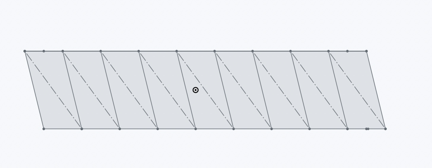
I added variables to my Onshape sketch today, which allowed me to easily switch between a 6, 8, or 10 sided Kresling. I based the radius of each Kresling on a circle of radius 4 cm, and used that to calculate the side length of an n sided polygon that would inscribe the circle. The angle of each triangle within the module can be adjusted based on the number of sides of the polygon, and I used an offset of half the side length of the polygon for my parallelograms. With these calculations, I was able to print and create a 10-sided kresling. Olivia and I also met with Crystal, who has experience with origami robotics. We talked through lamination techniques and ways to adjust the stiffness of the material we want to fold. Our next prototypes will involve card stock and plastic.
Monday, 8/1/22: I worked on creating Kresling designs with different numbers of sides today. I created an 8 sided kresling by calculating different angles than those that were used on the 6 sided kresling. Drawing out each design was becoming time consuming and led to several inaccuracies in angles due to human error, so I designed my next prototype in Onshape by using the sketch/drawing feature. It was a little hard to print out my design and get it to be the right size, but I eventually learned how to use the drawing feature in Onshape and map my design to the size of regular printer paper. I also tried to create kresling designs with multiple units/modules in order to better mimic the prolate shape of a heart. However, this prevented the middle of the kresling from changing radially as each unit has a fixed area at the top and bottom. Stacking two together achieved the right shape of a prolate, but ultimately failed to get the right radial compression we needed.
 |  |
| sketch of 8 sided kresling design | stacked kresling |
Week 6
Thursday-Friday, 7/28/22-7/29/22:
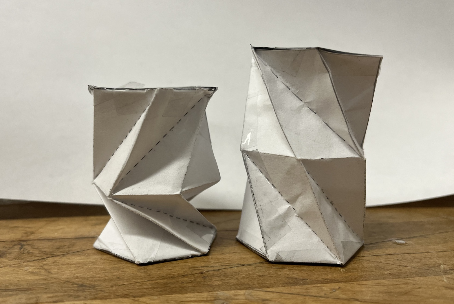
compressional and torsional movement of Kresling
Ali and Ileana introduced Kresling origami as a method of achieving both vertical compression and torsion. Olivia and I worked to create scaled up versions of one Stanford lab's version of Kresling origami. Making sure the measurements were accurate was painstaking when carried out with just a pencil and ruler, so with later prototypes Olivia and I used a printer for our designs. We used regular printer paper, card stock, and construction paper, all with varying degrees of success. The stiffer paper resisted deformation better than standard printer paper, but it was also harder to compress. We used thin cardboard to form the cardboard hexagonal plates at the top and bottom of each prototype.
 |  |
| printer paper Kresling v1 | card stock Kresling v2 |
Wednesday, 7/27/22: We had our weekly team meetings again today. In our debrief with Mark, we went over our different options for moving forward with the prolate, ultimately settling on pursuing two paths. Olivia and I casted a second, identical prolate to test out the iris mechanism idea, and we are looking into adding more springs to reduce bulging in the original prolate. Casting the second prolate resulted in the same air bubbles as the first prolate, so we had to recast the prolate multiple times to fill those in. We used Ecoflex 00-20 for the entire prolate. For the original prolate, Ali suggested filling it with water to simulate a more realistic version of the heart pumping. This could also eliminate our bulging problem. Unfortunately, the water idea posed more problems (maintaining the correct pressure + where will the volume of displaced water go?) This also will increasing the strain on the springs/twisting plate system due to the increased density of the water as opposed to air. Olivia and I also worked on assembling the iris mechanism today. I had to sand down the individual flaps of the iris since the supports created by the printer resulted in an uneven surface that added a lot of friction to the system.
Monday, 7/25/22:
prolate bulges around springs
We moved towards using fishing line for the springs and twisting plate on the prolate. Olivia and I measured the force required to pull/hold the plate and springs while compressing the prolate. We tried different variations, including the open prolate, the prolate with constant volume, and the prolate inflated by 50 cc. I used plastic spacers to fit the springs on the prolate, and decided to separate the top spring from the middle and bottom springs to minimize friction. I also added another spacer on the opposite side of the top spring since it tended to slide up when pulled. After I attached the springs and the plate, I tested pulling both at the same time to mimic the twisting + compression motion of the heart. This led to a lot of bulging between the springs, which isn't ideal. Some possible solutions could be to use bigger springs to minimize gaps or to decrease the volume of the prolate while compressing. Olivia and I also looked into some CAD models of iris mechanisms, and we plan on designing one of our own to make it customizable.
Week 5
Thursday, 7/21/22:
hanging sensors dipped in silicone
We did a lot of sensor testing today. I used two sensors I'd made yesterday that were coiled with conductive string to bring the electrodes to the same end of the sensor. I dipped both in silicone (Ecoflex 00-10) that I added thinner to in order to achieve a thinner coating that wouldn't have too big of an impact on sensor stiffness. The coating protected the thread from touching any water/saline solution which could mess up the readings when placed in the heart. After the silicone cured, I tested the sensors in both water and a saline solution. The resistance readings were unaffected, which was a success and meant that the silicone was protecting the thread from interacting with either solution.
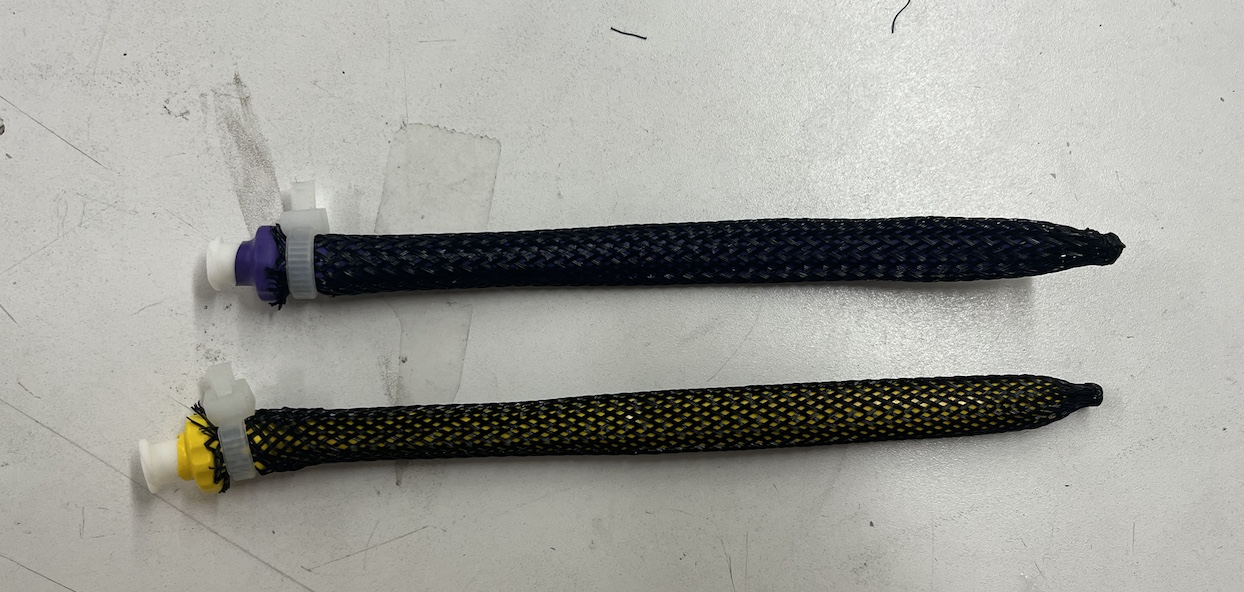
We started running out of the super thin silicone tubes, so for our next sensor prototypes Olivia and I returned to the stiffer silicone tubes. We explored using wire coiled around the sensors instead of the thread. The wire came with a coating that protected it from interacting with any solution, but we had to scrape this coating off before soldering it to the electrode on one end. I also made a regular resistance sensor with the thicker tube for Ali and Ileana to compare a new sensor filled with saline water to. I used double sided acrylic tape to seal off the corked ends of the sensor and sewed a string through to allow the tabs to be pulled.
top: normal resistance sensor; bottom: coiled wire sensor
Wednesday, 7/20/22: The cardiac corner had both our weekly meeting with Mark and our team meeting today. Olivia and I brought Mark and Ileana up to speed with our new prolate base and bottom plate and shared our McKibben experiences with Ileana. In our team meeting with Ali and Ileana, we discussed our options for mimicking the compressive twisting motion of the left ventricle. We decided against using McKibbens due to complications with embedding/attaching them and the lack of availablility of different balloon shapes/materials. Another opition was using compressive springs, which posed some problems with not getting the right pressure and being a bit difficult to manage with the large amounts of friction in the system. Ali suggested manually pumping/removing air from the prolate, but that also risked collapsing the prolate and there was no compression/radial shrinking. Ileana suggesting using an iris mechanism, which both twists and shrinks radially at the same time.
Tuesday, 7/19/22: We attached the bottom acrylic plate to the bottom of the prolate today. Olivia and I looked up what the vertical and torsional strain of the left ventricle should be and mapped that to where our plate should be placed. The bottom of the left ventricle should turn by about 20 degrees, and since our plate was located about a centimeter above the bottom of the prolate, we calculated that the plate should rotate by 15 degrees. We also calculated that the vertical strain of the heart should be about 1.3 cm of compression, so we attached the plate at the appropriate angle needed to rotate the plate by 15 degrees with 1.3 cm of vertical displacement. We attached the base by using sand paper to score the acrylic and adding a primer that we left to cure for 2 hours. Then we used silicone (Ecoflex 00-20) to seal the plate to the base, adding it in two separate batched to let both sides of the plate cure to the prolate.
base attached to the prolate
Monday, 7/18/22: I tried making some sensors today. Ali showed me how to work with the small silicone tubes and we attempted to make some sensors that could alter capacitance by wrapping a sensor with conductive thread. The silicone tubes were very small, making them very difficult to work with. We had to inject ionic conductive fluid into each sensor tube, making sure there were no air bubbles. Even getting the needle to fit into the tube was a challenge, since the needle tip and tube were about equal in diameter. After filling up the sensor tube, we had to plug the ends with a bit of wire that would be our electrode, and then tie off the end connections and seal them with super glue. The sensors are pretty delicate, and since we stretch the tubes to test them, we often had one electrode pop out of the tube. Wrapping the sensors in the conductive thread also proved challenging because the tubes were very stretchy, so I had to roll the sensor between my fingers to slowly end up with a wrapped sensor. My first sensor did not have the thread coiled around it enough times, which prevented the resistor from stretching. We also attended our weekly SURI meeting and learned more about what other students were working on.
sensor attempts
Week 4
Friday, 7/15/22: I helped Ali retest the resistance sensor today. The sensor was made out of a stretchier tube, which allowed to to expand more easily along with the prolate. The thinner tube helped improve the sensitivity and accuracy of the sensor as pressure/volume changed. I also reattached the prolate to our new base and worked on improving the compressive springs around the prolate. The original string we were using added a lot of friction to the system, and I found that replacing that string with fishing line greatly reduced friction. I also modified the attachment at the ends of the springs to be super glued together instead of using tape, which was a lot more temporary and clunky.
Thursday, 7/14/22:
compressive springs
Today we explored alternative ideas to McKibben actuators. Mark suggested we use a spring wrapped around the prolate cylindrically with a string through it to replace the compressive McKibbens, and we decided to try using another piece of acrylic with string wrapped around it to mimic the twisting motion of the heart. We were able to find some springs of the right diameter and length so I created some mock spring actuators.
compressing the springs
The springs ended up working pretty well, and it helps that using strings to control compression allows us to bring in servo motors and have more control over how much we're compressing our model.
After working on the springs, Olivia and I updated the CAD model of the base to add more holes into the top and bottom base to tie strings through. We went to the PRL to laser cut a new base and bottom attachment, all with more holes to allow for the strings to feed through. I also helped Ali test out one of her resistance sensors by attaching the prolate to an Arduino and monitoring pressure. We're going to have to reattach the prolate to the acrylic and are considering also attaching the bottom base piece to prevent slipping.
Wednesday, 7/13/22: Despite our best efforts, none of the actuators ended up curing well. All of them ended up very sticky, though the actuators with primer ended up being the least sticky. Ali suggested doing a patch test on the balloon and mesh to see if the material type was preventing the silicone from curing. Apparently some types of latex can cause problems for silicone, and most balloons are made out of some latex blend.
patch test with silicone
The silicone on the mesh and paper ended up curing, but the silicone on the balloon remained uncured and sticky. A quick search for "long party balloons" and perusal of clown/party reddit forums revealed that there are no latex free balloons in the shape that we want - apparently this is a common problem for those with latex allergies who want balloon animals. We may have to turn to medical balloons or could attempt to create our own out of silicone.
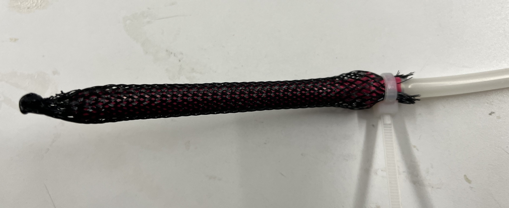
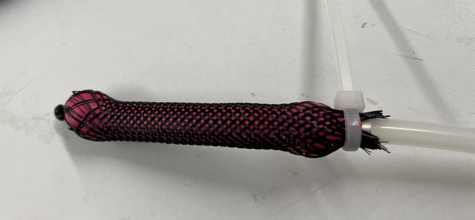
Tuesday, 7/12/22: Olivia and I focused most of the day on making 8 actuators and coating them in a layer of silicone. We used heat shrink to prevent the mesh from fraying, which ended up working really well (all of our actuators formed a perfect seal on our first attempt!) Creating 8 actuators allowed us to test out different shapes and methods in order to find the best way to cure silicone onto the actuators. In the past, when we've added a layer of silicone onto an actuator, the silicone has remained uncured and is very sticky. To test different methods, we coated half of the actuators in Ecoflex 00-20 and the other half in Ecoflex 00-30. Two of the actuators were sized to fit around our prolate and were shaped into a circular loop using a rubber band to hold two ends in place. The rest were sized to wrap vertically around our prolate. We covered three of our actuators in primer and allowed them to set for 2 hours before adding silicone. The rest were covered in silicone directly. After dipping each of our actuators in silicone, we used a heat gun to speed up the curing process and hung them overnight to dry.
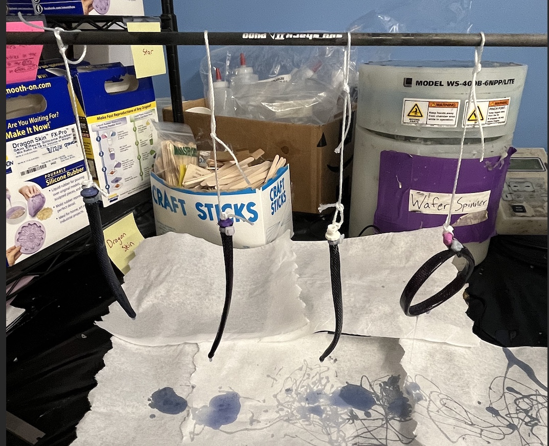
hanging up our actuators overnight!
a couple of our actuators in detail
In the afternoon, Lawrence taught a few SURIs how to solder and crimp. I'd never gotten the chance to solder before so it was nice to get some hands-on experience with that. Out of all the things we learned, I found that crimping wires was the most difficult because it required the most dexterity with bending the metal + ends of the wire. I managed to get a few attached correctly (affirmed with a conductivity test via a DMM), but I went through quite a few crimping pins before doing so.
Monday, 7/11/22: Mark got the tap we needed to create threads in the center of the acrylic base for a tube + syringe attachment. It took a bit of force and some more oil to get the tap through (maybe next time we'll start with a bigger hole in the base?) but we eventually got it working and set the prolate up with the original pressure sensor. I got the Arduino connected with some Matlab code that Ali sent me and was able to graph the pressure change over time. Olivia and I also verified that the pressure sensor was consistent by tracking how it changed with volume. The image on the bottom left displays the graph; we measured the pressure at each volume twice, and different iterations are represented by two different colors.
 |  |
| graph of pressure vs volume change | pressure monitor setup |
Week 3
Friday, 7/8/22: After our weekly BDML team meeting, we returned to the McKibben actuators and tried to optimize the fit of the actuators and minimize the fraying of the mesh. We ran into some trouble creating a perfect seal around the end of the balloon that attaches to the pump, but were able to solve this by using a few very small rubber bands and a zip tie. We also found a plastic connector piece that improved upon the original metal piece that we used, which was larger in diameter than our mesh and ended up popping off when too much pressure was applied.
failed actuator attempt
One of the supplementary Roche paper readings suggested dipping the actuators in silicone after being fitted around the mesh. We weren't sure how this would impact the strain of the actuator, so we decided to test it out with more ecoflex 00-20. To cure the actuators, we used a heat gun and rotated the actuators for about 5-7 minutes. Once cured, we retested the actuators with a silicone layer and found that strain was not significantly impacted. Using silicone around the actuators will allow us to attach them to the prolate heart model a lot more easily, since silicone generally only bonds to silicone.
actuator with silicone layer
Thursday, 7/7/22: Today we casted the prolate and fitted it to the stand. We used a syringe to inject the silicone into the 3D printed prolate mold and tried to minimize air bubbles. Despite our best efforts, we ended up with a couple of bubbles (one by the top hole and one by the lip of our prolate. Olivia recasted the sections that were missing and managed to fill them in pretty nicely. We decided to use silicone (ecoflex 00-20) because the Young's modulus of elasticity most closely matched that of a human heart in diastole. The material is very stretchy, and is a lot more malleable than the last prolate example.
prolate fitted on the base!
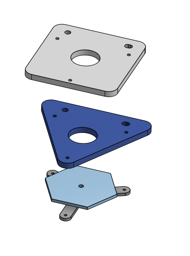
Wednesday, 7/6/22: The main accomplishment today was laser cutting the acrylic base and getting it to fit onto the stand that will eventually support the beating heart simulator. Olivia and I had some trouble getting the holes on the acrylic to line up and fit the screws for the base, but we were able to drill a couple of the holes in the acrylic to make everything fit together. It was my first time using a laser cutter, so it was nice to learn from Tony and see the process of converting a CAD file to something that could be read by a laser cutter and eventually a physical piece of acrylic. The prolate mold finished printing late in the afternoon; Olivia and I are planning on casting the prolate sometime Thursday morning after Ali returns.
laser cut acrylic base
base fitted to the stand
Tuesday, 7/5/22: I worked on the cardiac corner project today, assisting with the development of a bench top beating heart simulator. Olivia and I followed a tutorial on how to create a McKibben actuator using materials we found around the lab. McKibben actuators are made of an expandable inner tube similar to a balloon that is wrapped in a contractable mesh. The combination of the tube and mesh results in an actuator that contracts linearly upon experiencing radial expansion in the inner tube. This replicates the muscles around a bladder or heart and is one possible option for creating the beating heart simulator. Olivia and I also explored other possible options via an informal literature review, though many setups involved the use of a porcine heart. The use of organic material isn't viable for long term testing because it tends to stiffen or decay after a day.
balloon is deflated
balloon is inflated, actuator is contracting linearly
I also developed a CAD model of a base and clamp that would affix a prolate made of silicone to a stand that would be used for a beating heart simulator. The base had to fit around the lip of the prolate and seal the open top in order to prevent leakage.
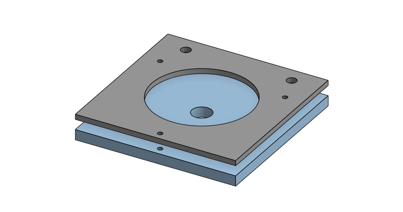
CAD model of base and clamp
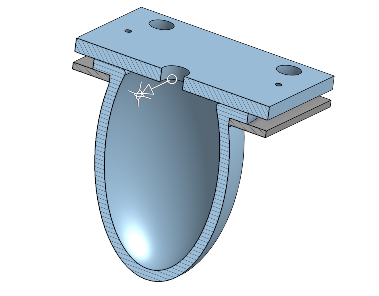
section view of base and clamp assembly fitted around model of the prolate designed by Olivia
Week 2
Tuesday-Wednesday, 6/28/22 - 6/29/22: I learned how to use Tinkercad and some Arduino today. I built a basic timed stoplight circuit in both the Tinkercard simulator and on an Uno R3 Arduino base. I also continued to work on designing a spacer in CAD to attach bevel gears to for a differential wrist. Wednesday involved lots of Arduino.I worked on getting some micro servo motors to power a fan. I started with a simple program that used delays and different angles to move turn one fan, then used a potentiometer to control the motion of the servo. I eventually added in a joystick and second servo motor. The joystick controlled the motion of the different micro servos, depending on whether you moved the joystick in the x or y direction.
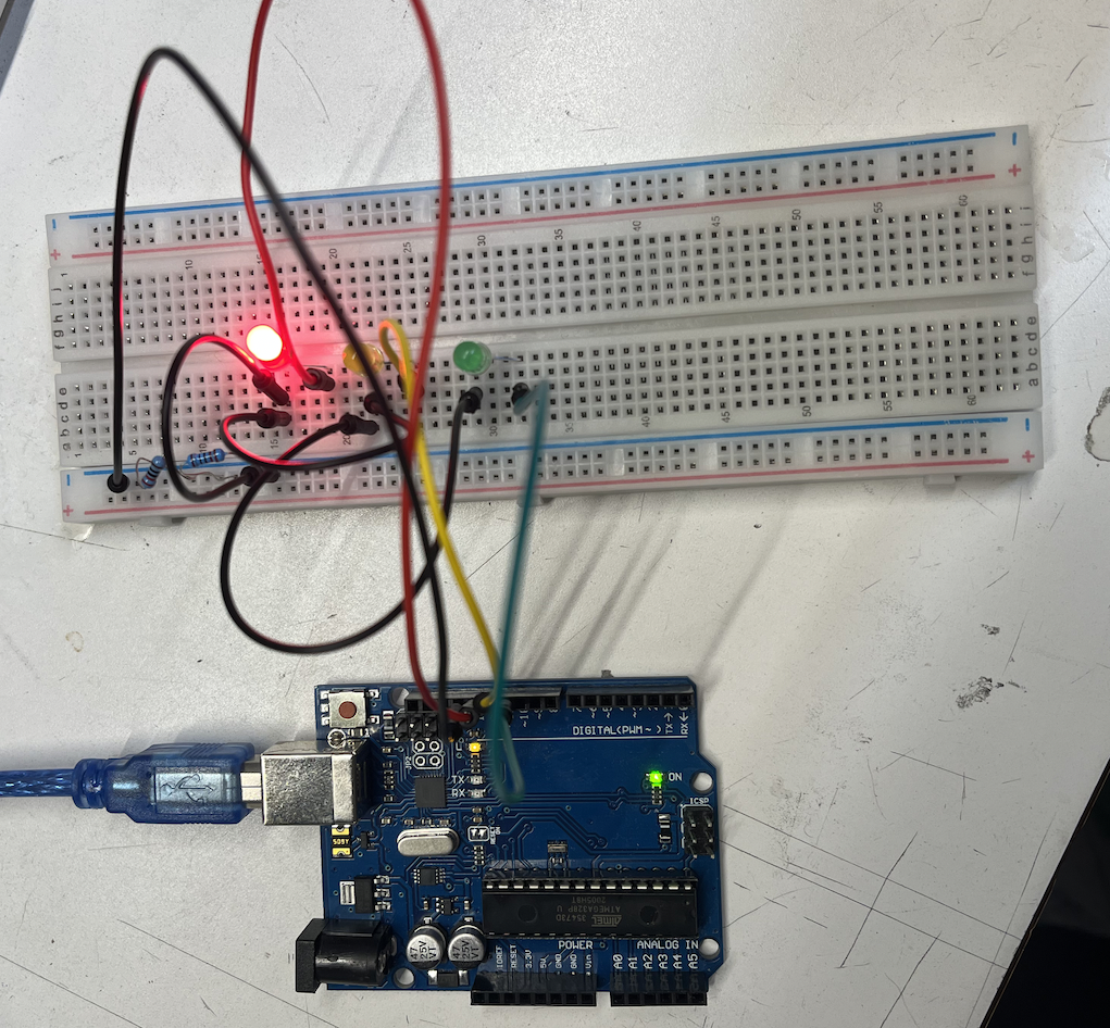 | 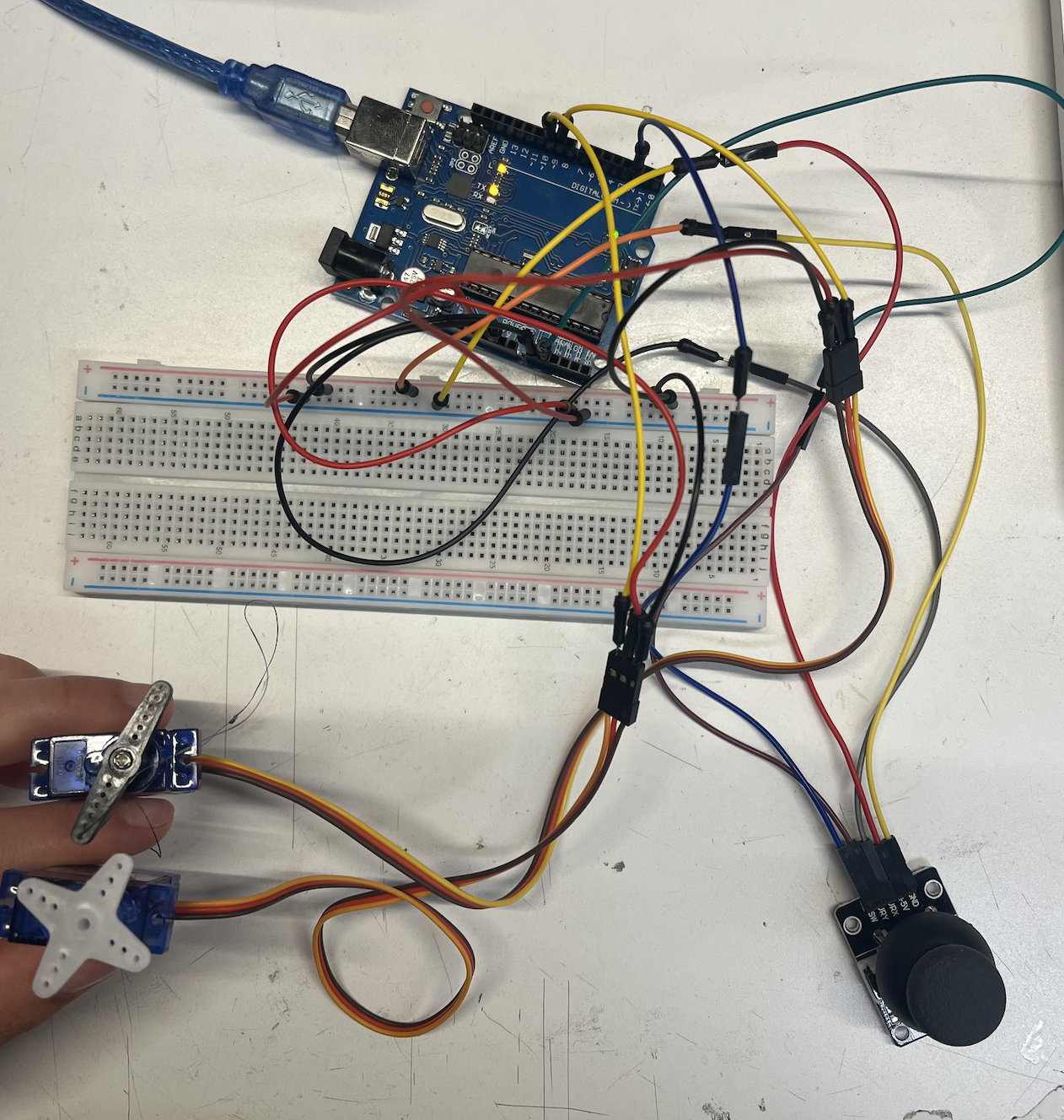 |
| stoplights | servos and joystick |
Monday, 6/27/22: We had a panel of PhD students sharing their experiences in grad school with us today in our weekly SURI meeting. I also sat in on a TRI meeting where we talked about different high level tasks that robots could possibly accomplish, like sorting groceries or putting away laundry. Rachel gave me a 3D printed differential wrist as an example of what a robotic hand could use to navigate through a crowded shelf. I examined the CAD design of the wrist and worked on how to simplify/shrink the bevel gears using parts from McMaster-Carr.
Week 1
Tuesday - Friday, 6/21/22 - 6/24/22: The second day in the lab was filled with more Onshape tutorials. I finished up my fidget spinner and followed a tutorial to design and animate a linkage. After going through a basic lab safety training with Dane, the entire campus lost power, halting work for the rest of the day. Conveniently, Wednesday was our lab's scehduled retreat, so we went to the beach to meet other lab members and discuss our summer goals. The power didn't end up returning until early Friday morning, and upon getting back into the lab I sat in on my first BDML weekly meeting where we discussed different projects that would be going on this summer and set the dates for a backpacking trip later in the summer. The rest of Friday was filled with different tutorials around the lab. We were introduced to the UV laser cutter, got Onshape tips from Rachel, and Tony led the SURI's through a silicone/urethane casting tutorial. We also learned about the available 3D printers in the lab and the advantages of using each.
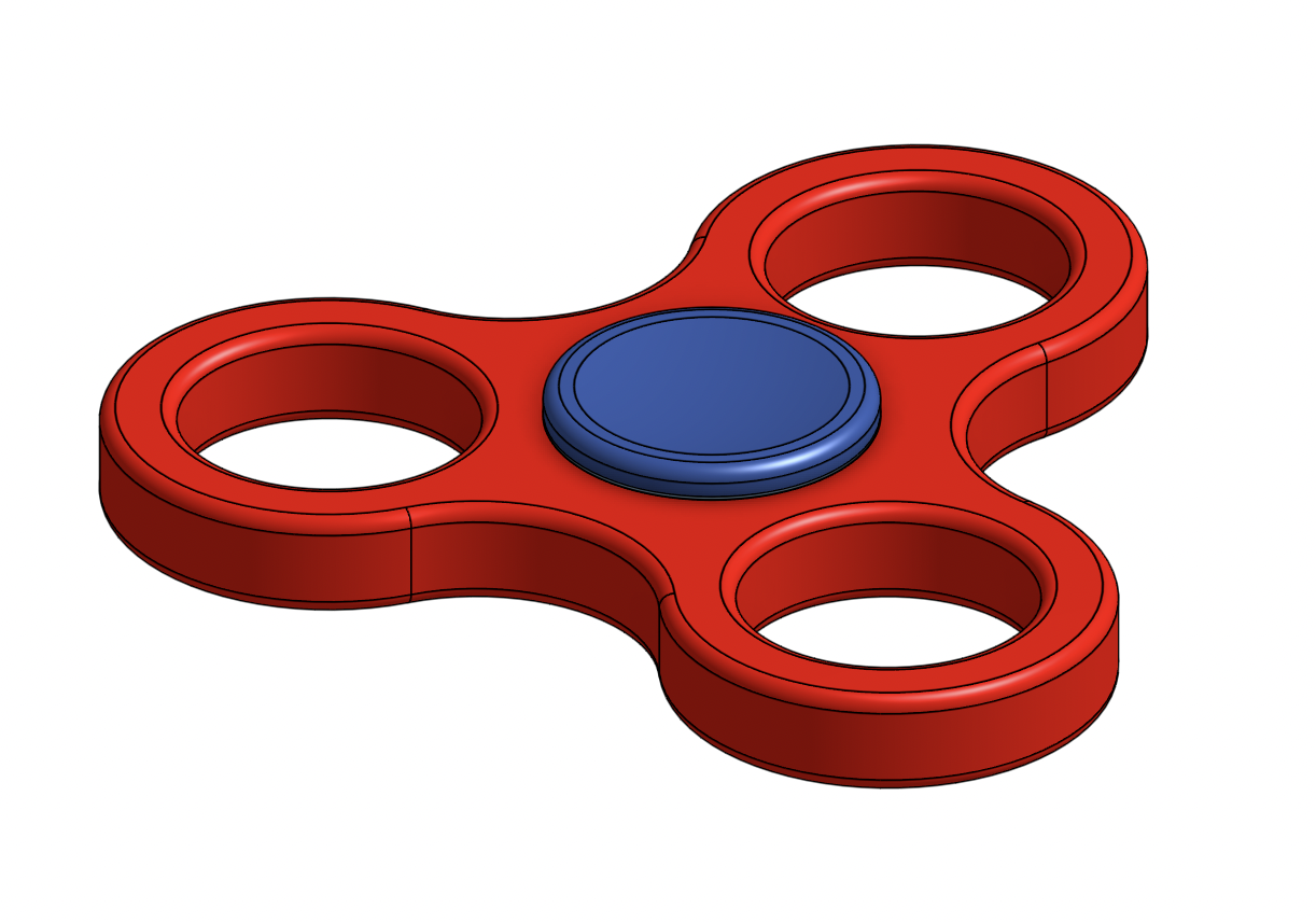 | 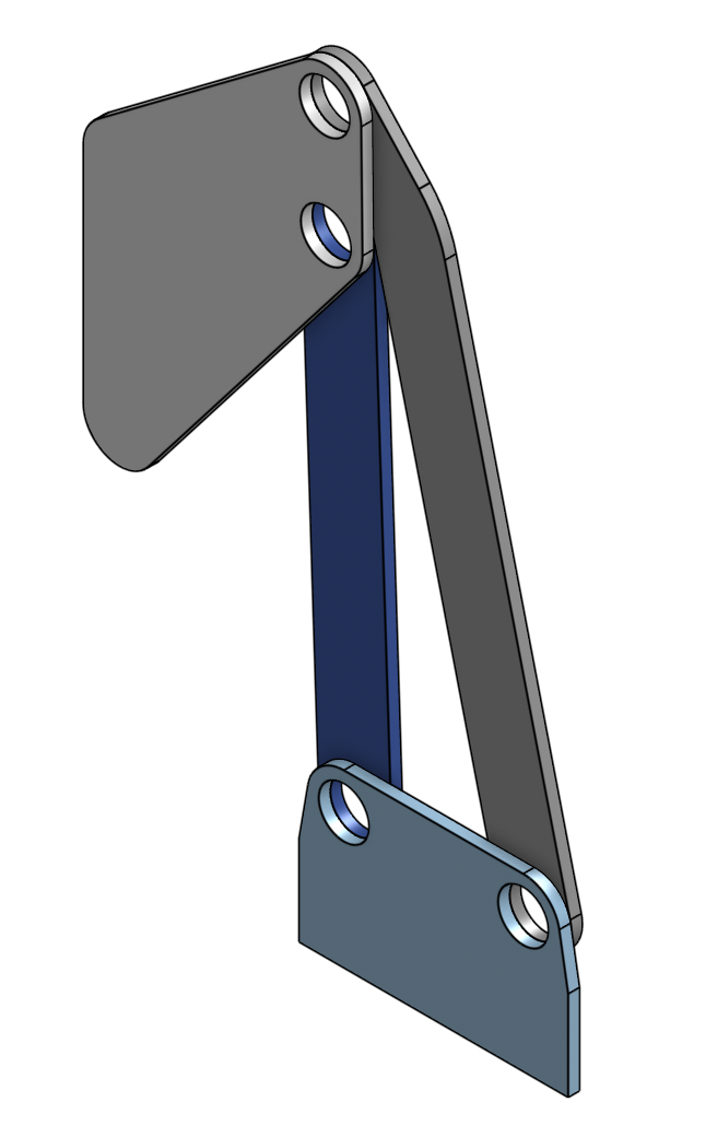 |
| spinner | linkage assembly |
Monday, 6/20/22: Today was our first day in the lab. After the SURI kickoff meeting, I learned how to use the BDML website with Mark. We also joined in on a tactile sensing meeting with Dane and Hojung where we talked about normal and sheer forces and how robots can interpret human gestures. Later in the afternoon, I finished up the required STARS safety training. I also started a few Onshape tutorials and worked on using CAD to design a lego block and fidget spinner.