Categories: ME112Notes, Crawlers2014, QandACrawlerFinePoints
On this page... (hide)
- 1. Crawler Setup and Testing
- 1.1 Drag Testing
- 1.2 Slippage Testing
- 1.3 Force Sensing and FBDs
- 2. Crawler Motors
- 3. Lego Stuff
1. Crawler Setup and Testing
28Jan2015: Lots of the material below is relevant for 2015. However we probably won't be using force sensing resistors (FSR) for contact force sensing. Also see:Crawler Fine Points.
1.1 Drag Testing
We will be setting up a small plastic bucket with sand and a pulley on one of the tracks. There is also a digital scale. With these you can find how much weight is needed to just barely drag your crawler up the track with the motor disconnected. This will be an estimate of m*g*sin(theta)+F_roll, where F_roll is the total rolling resistance (e.g., per Assignment 2).
You can also try other variations, for example, leaving the your gearbox connected to the driven wheel(s) and disconnecting it at the motor. In this case, you'd be getting the drag force for Froll plus the power required to operate your transmission due to friction.
OK - for those who already have their crawler running adequately and want to explore some fine points of testing and analysis we are starting a new curated FAQ: Q&A: Testing and Analysis fine points
1.2 Slippage Testing
Differences between theoretical and actual wheel speed are only due to slippage at the wheel. Since speeds at places other than where the wheels touch the shaft are strictly governed by the gearing ratio, all of these other inefficiencies are simple torque losses, not speed losses. To measure slippage, you'll need to time your crawler moving over a predetermined distance to find its linear velocity. Then, by measuring the number of wheel rotations directly (or indirectly through current draw), you can calculate how far it should've traveled in that time period. The difference between theoretical and actual speeds will be the loss due to slippage.
1.3 Force Sensing and FBDs
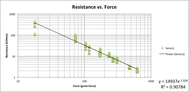
We ask for a free body diagram (FBD) of the crawler on the track. We want a rough preliminary version for the first design review and a good one for the report. To get quantitative data for this force analysis you can use the digital scale (for mg) and a special test track that we prepared with a Force Sensing Resistor (FSR) whose resistance changes as a function of the pressure when any wheel rolls over it. This is not a very precise measurement, but it gives you a useful approximate value for your FBD. Of course, you still don't know the tangential (traction) forces, but from the overall force balance you can probably deduce this for the drive wheel.
Feb 9: Here is the resistance/force plot for the FSR with updated data for a better fit at higher loads. Some things to keep in mind:
- FSRs are not super accurate. Take multiple measurements, rolling over several times, to get a sense of repeatability.
- The FSR is sensitive to pressure. If anything gets lodged in the pocket where FSR lies, the reading will be wrong.
- There are little pieces of rail you can use in case you want to measure the force for a wheel or roller that is normally on a power rail
- Realize that you want the clamping and loading conditions to be the same when going over FSR are they are in use. Try to set up so all loads are as they would be in operation as much as possible.
- Go slow. You will be reading resistance with a multimeter, which cannot track fast changes
There are too many possible design variations to say much more about this in general. We'll talk about it with each team as their design evolves.
2. Crawler Motors
Your Lego motors have a tiny 2-stage planetary gearbox built in. The setup is similar to the Drill motors, with torque coming in on the sun gear and going out on the planet carrier. The number of teeth is 11 for the sun, 16 for the planets. So the ring gear should have 11+2*16=43. This would lead to a total speed ratio from input to output of N = (1+R/S)^2 = (1+43/11)^2.
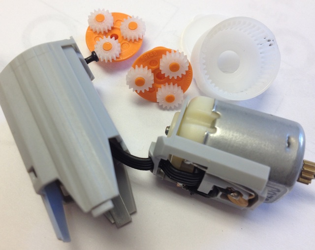
Inside your Lego motor
The motor by itself spins at a blistering ~11,000rpm at 9 volts. Therefore...
27January: We have decided that although the motor is rated for up to 9 volts, an operating voltage of 6 volts makes more sense.
30 January It turns out that the new Lego motor units have an internal thermal overload sensor. So measuring stall currents doesn't work very well. However, you can use the data that Marcus took for the motor by itself to get R and k for the motor:
Then refer to the single page notes handout Lego motors in 2014 from class Wed Jan 29 (and on Coursework) about how to compute the overall friction force for the Lego motor unit. You can measure the output no-load speed for the motor unit, with its built-in gearbox, and get some corresponding no-load currents. From these you can compute the combined friction torque T_fL where T_fL = (T_fg + N*T_fm), where N is the speed ratio as explained above.
If you get a range of friction torques, you can pick one that seems likely to correspond to your actual operating speed.
Then you can measure volts, current and speed to get Tf, R, and k. The numbers you get will be for a somewhat fictitious motor that represents the combined effect of the actual Lego motor and its internal gearbox. This should work OK because everything is linear and you will be getting the combined Tf of the motor itself and the tiny gearbox.
Note: If you want a pretty good estimate of the motor+gearbox performance under "realistic working conditions" you can stick a pulley on the motor shaft and lift a weight using a string. The output power is mg*v_y where v_y is the upward velocity of the weight. The input power is V*i. So you know enough to compute efficiency of the motor and its little internal gearbox immediately.
3. Lego Stuff
Lego spur gears from Technopedia
3.1 Lego Design and Assembly Tips
- Lego Design -- A handy guide go Lego-based robot design from Rice University. Good information on typical spacings, geometries that one can make.
- A lego enthusiast's observations on Lego gear strength and loading recommendations
- Lego design manual from Berkeley (PDF)
- Table of Lego gear meshing dimensions and possible combinations
- another good guide from MIT (Adobe Postscript)
3.2 Some Neat Lego Mechanical Examples
- http://www.youtube.com/watch?v=cYw2ewoO6c4 -- A Turing Machine made of Legos! (Turing Machines were sort of a precursor to modern computers; WWII era)
3.3 Lego Material Properties
Strength
According to one source -- Material properties of ABS are similar to Lego plastic (Yield strength 5KPsi, Tensile Modulus 360KPsi, Elongation 50%, Softening point 220DegC, Specific Gravity 1.05 Kg/M3).
Another page quoting the 5000 psi number: http://orionrobots.co.uk/Lego+Specifications
5000 psi seems a safe lower bound. Like many polymers, ABS is measured in a 2-point bending test and the "flexural strength" can be as high as 7500psi. For comparison, the nylon used in many cheap plastic gears has a yield strength of about 6000psi.
So, what should our allowable adjusted stress be? We are probably going for less than infinite number of cycles and we don't need very high reliability. Perhaps 4000 psi if feeling conservative and 5000 psi if feeling brave.
Friction
ABS is quoted as having a coefficient of friction of 0.5 for sliding on itself. With even a tiny bit of lubrication (including the oil that comes from contact with human skin) this value will be lower. With reasonable lubrication, a value of 0.1 should be achievable.
3.4 Lego Gear Dimensions and Calculations
Nice page with animations and information of various Lego gear combinations: http://www.technicopedia.com/fundamentals.html
Another page: http://orionrobots.co.uk/Lego+Specifications
With Legos, everybody thinks in terms of fundamental Lego spacing units. However, for stress analysis it's useful to compare Lego gears to other plastic gears that one can find in catalogs. This allows you to find the Lewis Form Factors, J, for gears of similar size. The consensus seems to be the following:
- Lego gears have a metric module of 1, which is the same as a pitch of 25.4 teeth per inch of diameter.
- Pressure angle is likely to be about 20 degrees. (This is the most common angle with modern gearing.)
- Face width is approximately 1/8 inch. Perhaps more precisely: b = 0.14 inches? - according to a measurement somebody took with calipers in 2011. But note that not all Lego gears have the full face width. In particular, the crown gears (Lego's version of bevel gears) do not have a full face width.
From http://orionrobots.co.uk/Lego+Specifications : In the Lego system, technic gears have a ratio that the number of teeth are 8 times the diameter, or 16 times the radius in stud pitch. Conveniently - the number of studs, and Diameter in Millimeters seem to be the same. Note: one "stud" is 8mm. So: 16 tooth gear is 2 studs = 16mm => diametral pitch = 1mm.
1 Feb 2014: Here is a gear stress spreadsheet for the case of Lego gears. The parts in pink indicate missing information or things that need to be modified. Note that small Lego gears (8 amd 12 tooth) have fewer teeth that is recommended so the J parameters are terrible and there may not be load sharing.
3.5 DIY Lego-compatible gears
Can one make Lego-compatible gears using the Lasercam? Sure: https://docs.google.com/a/stanford.edu/document/d/194K2LttM1R28KkHRkAzQaF9A6WYTC7_Ws-NpJPZAmek/edit
It is discouraged for the crawlers project because of the short time frame, but if you run out of other things to do...
3.6 Lego Worm Gears
A few teams are thinking of using the Lego worms. The advantage of a worm is that it advances the mating gear by just one tooth per revolution. So you can immediately get 24:1 or 48:1 in a single stage. The downside is that worms have more sliding, so the efficiency is typically lower, although adding some lubrication (e.g. vaseline or graphite) helps.
For strength, in the case of Lego, the worm mates with a regular spur gear instead of a special worm gear. So the main issue for strength is probably not the worm itself but the spur gear that it mates with. Check visually to see if you are getting load sharing (more than 1 tooth in contact). Likely you are unless you are using a rather small spur gear in contact with the worm.
Now check the tangential force on the gear (which is axial force on the worm). Once you have the force, the main Lewis factor and etc. would be similar for that gear to what they would be if it were contacting another (smallish) spur gear. However, the Kv & etc. will be less appropriate -- the best we can do is take average values. (Actually, there are special AGMA formulas given in books like Shigley or Juvinal for the case of worm gears, but given that we don't have a true worm gear mating with the worm, and given that the formulas are for metal gears not ABS, it is not worth trying to apply them for a more exact result.)
In practice, the main issue is probably wear. If you can see bits of grayish Lego "dust" on the worm and/or the mating spur gear then you are having wear issues. This means that whatever your combination of frictional force and sliding speed (of the worm across the gear tooth) are, it's probably a bit higher than ideal. You can note this in your report.
3.7 Other Crawler FAQ (axles, brushes, direction change, ...)
Axles
- Can we cut our lego axles?
Yes, please do. We supplied you with long axles so that you can cut them to the length you need.
Brushes
- Best place to buy brushes?
It should be possible to improvise �brushes� from wire, paper clips, whatever - before trying anything fancy. Also, it is very possible to have multiple �brushes" in parallel � in case any single brush loses contact briefly. Just something similar in terms of being able to conduct electricity from the rails to your motor leads effectively. This can be anything from exposed wires splayed out, a springy strip of metal that flexes against the shaft to maintain contact, or whatever else you can come up with that won't hinder your crawler's movement while also holding a good electrical connection to the rails. To that end, looking around room 36 for scrap materials that are well suited to this, or simply browsing the aisles at ACE may be the best way of going about this problemBall point pens (the kind you click) have nice little springs inside that might be good for brushes...Another random thought: We are pulling power from two parallel rails. It is a bit like an electric toy train, which gets power from the left and right rail that it transmits through metal wheels into the motor. Perhaps a little metal wheel, or roller, or bead on a wire would be effective?