(redirected from Profiles.ChrisKimesSummerBlog)
Profiles.ChrisKimes, SummerBlogs
Chris's 2016 Summer Blog
Week 10
Friday, August 26
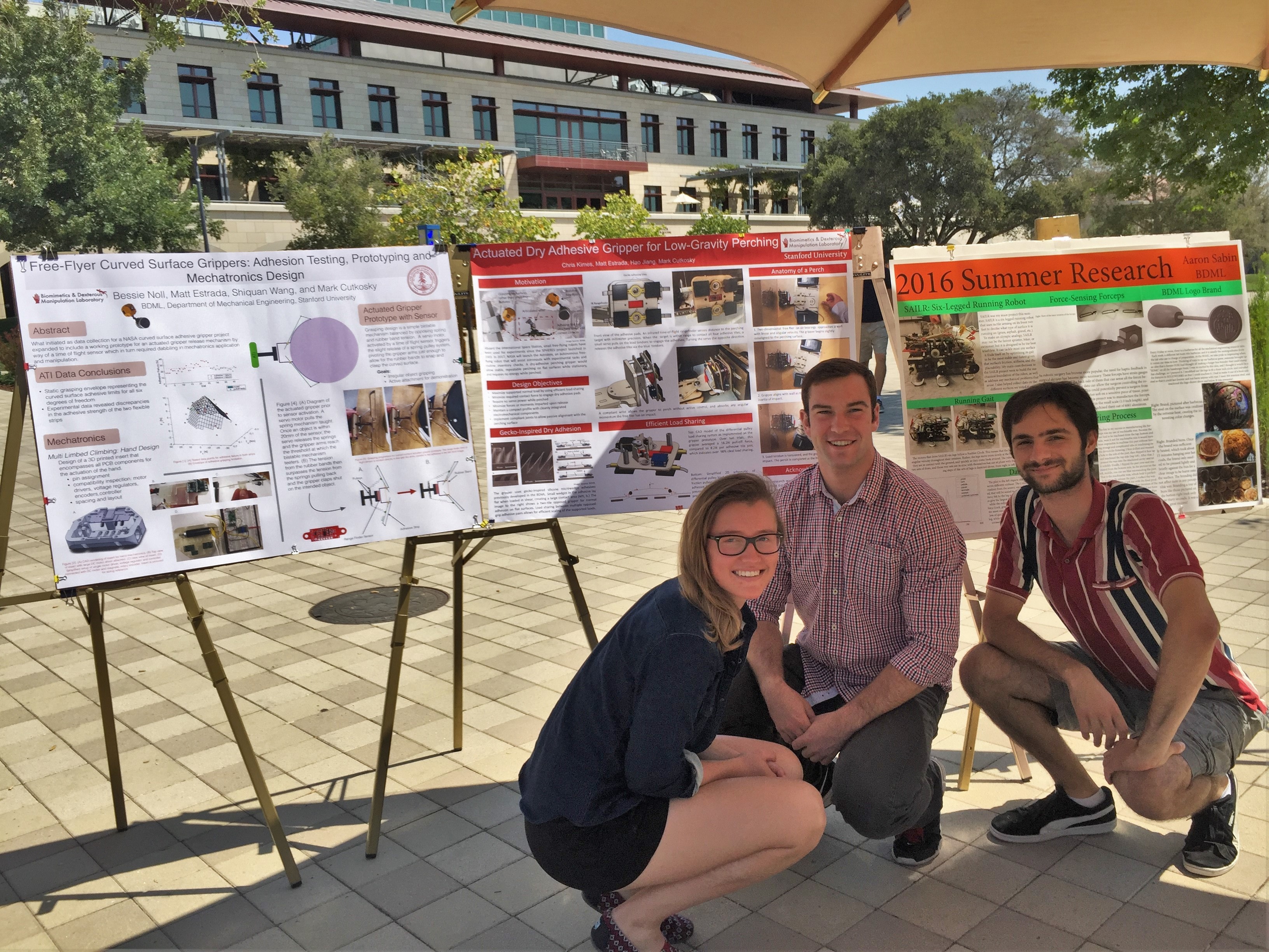
Today was my last day as a SURI. Bessie, Aaron and I presented our posters in lab meeting and Vanessa presented a slideshow. The poster session itself went really well; I got to see a lot of the cool stuff my friends in other labs had been up to, as well as show off my work to some of my undergrad friends, as well a few gread students and professors. Most people thought that my project was pretty cool (pro tip: if you build something cool, put lots of hi-res photos or CAD screenshots on your poster) and I'm pretty proud of my project this summer. Some of my biggest takeaways from this summer:
1. Electromechanical debugging takes 3x longer than you think it will. This will be useful for ME210, 218, and a career in mechatronics. 2. Being able to machine parts on a CNC mill is super useful, and I rearranged my schedule so that I can hopefully take ME318 this winter. 3. I like the research and experimental side of engineering, but I enjoy having performance specs and benchmarks to hit. This reassures me that I want to go into industry after finishing my planned coterm year. 4. I have a lot more to learn at Stanford and beyond. With only a year left of undergrad, and a lot more schedule freedom than past years, I want to take a lot more in-depth, grad level classes so I can master (or simply learn in greater detail) some of the concepts and things I've learned in undergrad.
After two years as a SURI, I love this lab and the people in it. Even though I was a lot more autonomous this summer, and a lot of the grad students were gone traveling at various times, I enjoy being part of this community of friendly, brilliant people. I love the friendly banter about sports, news, or dry-adhesion limits when I arrive in the morning, and I love hanging out at lab barbecues and sharing company over a burger. I can only hope that my workplace in the future is as filled with life as the BDML.
Wednesday, August 24
As the summer is winding down, I finished my poster today, and Bessie and I went over to FedEx to get them printed. I spent a lot of time on my poster, and I think it looks pretty good.
There was also an awesome perching meeting today. Capella shared some cool progress on the electrostatic gecko adhesives, but the real treat was Hao showing his gripper modeling progress with some beautiful MATLAB wire mesh plots of adhesion limits.
Tuesday, August 23
I got some data with the ATI today after a series of pull-off tests. The stock tile pairs averaged 8.2N of normal load before failure. I was surprised at how similarly they performed; the top pair supported 8.21 N and the bottom pair 8.18 N on average. The pull-off load for the gripper was an average of 16.2N, which means that the gripper is well above 95% perfect load sharing. The plots I took were a bit messy, and I had to discard a lot of bad trials, so I've decided not to put them on my poster unless I get a some cleaner-looking data tomorrow morning. I will be wrapping up my poster tonight so that I can submit it to FedEx in the morning for printing. My day was spent taking nice photos of the gripper and making some figures.
Monday, August 22
I spent all of today working on my poster. Tomorrow I will need to get some ATI data to have some nice plots. I still need to figure out how to get load-sharing data, so I'll talk to Hao tomorrow to see what my options are. Since I need to to finish the poster by tomorrow afternoon, most other things will be on hold until then.
Week 9
Thursday, August 18
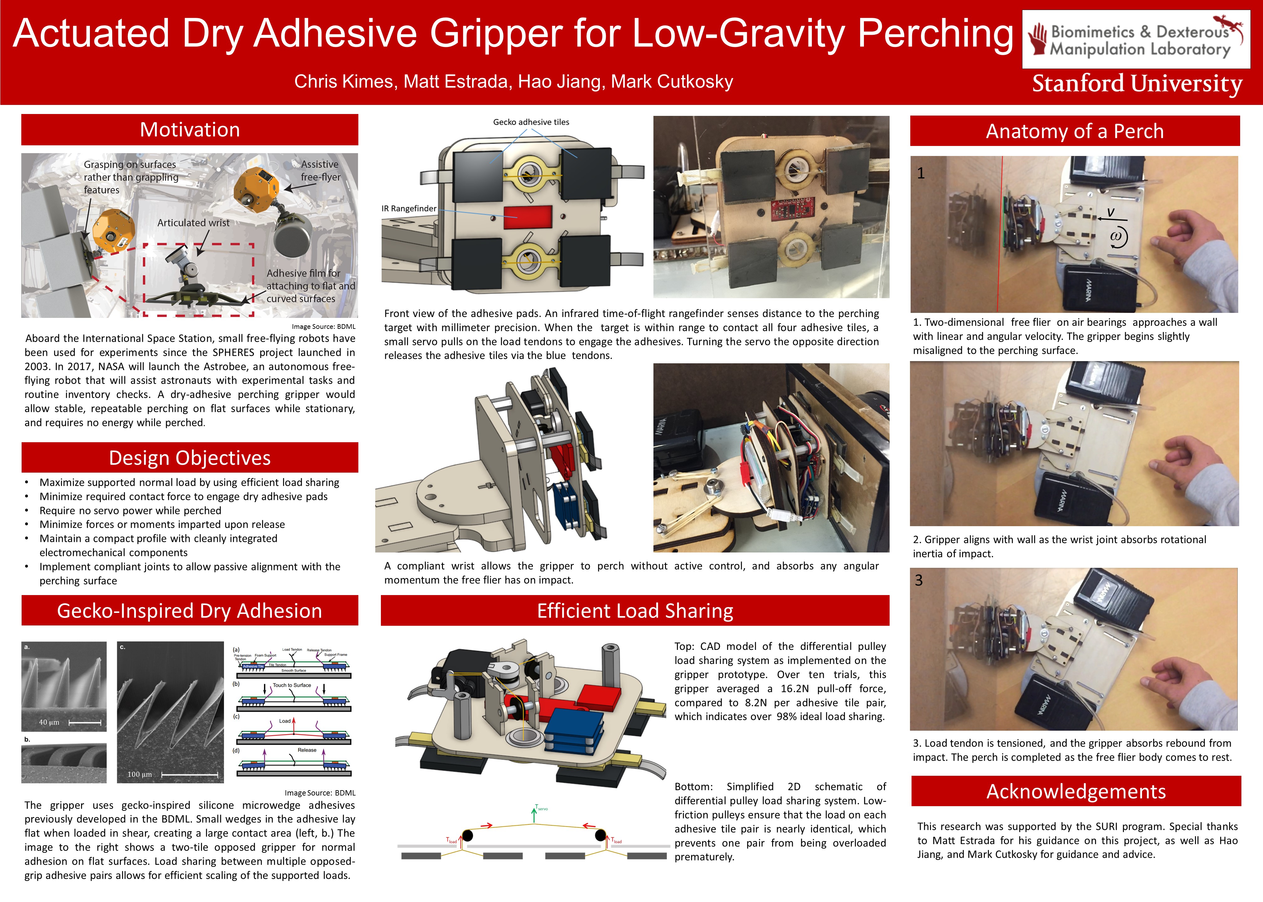
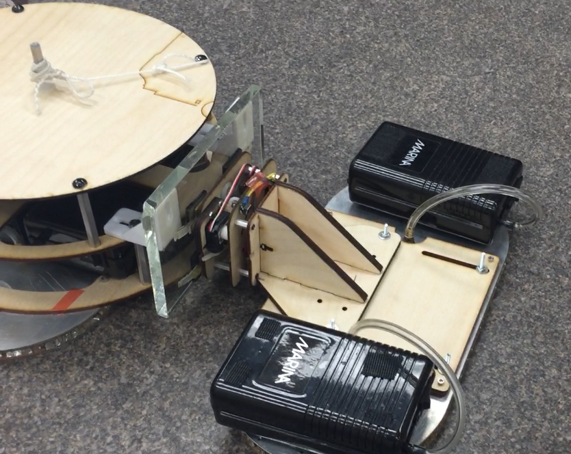
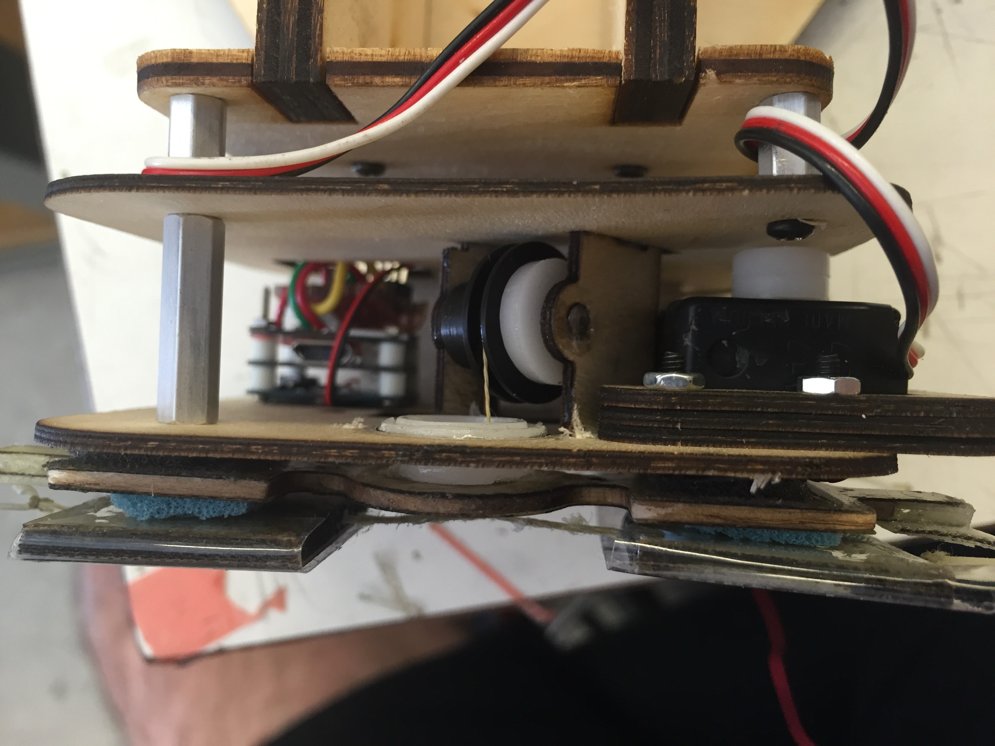
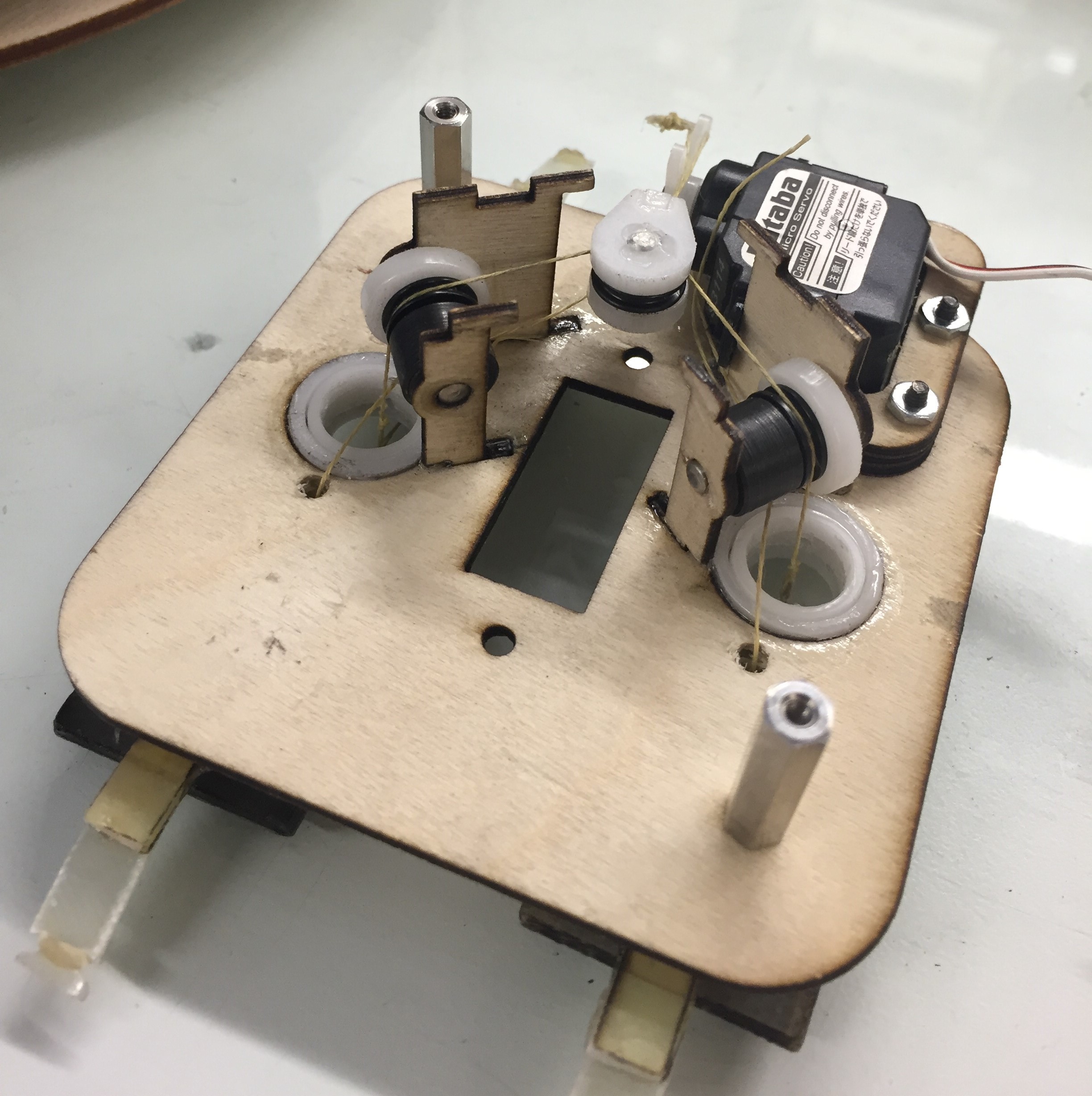
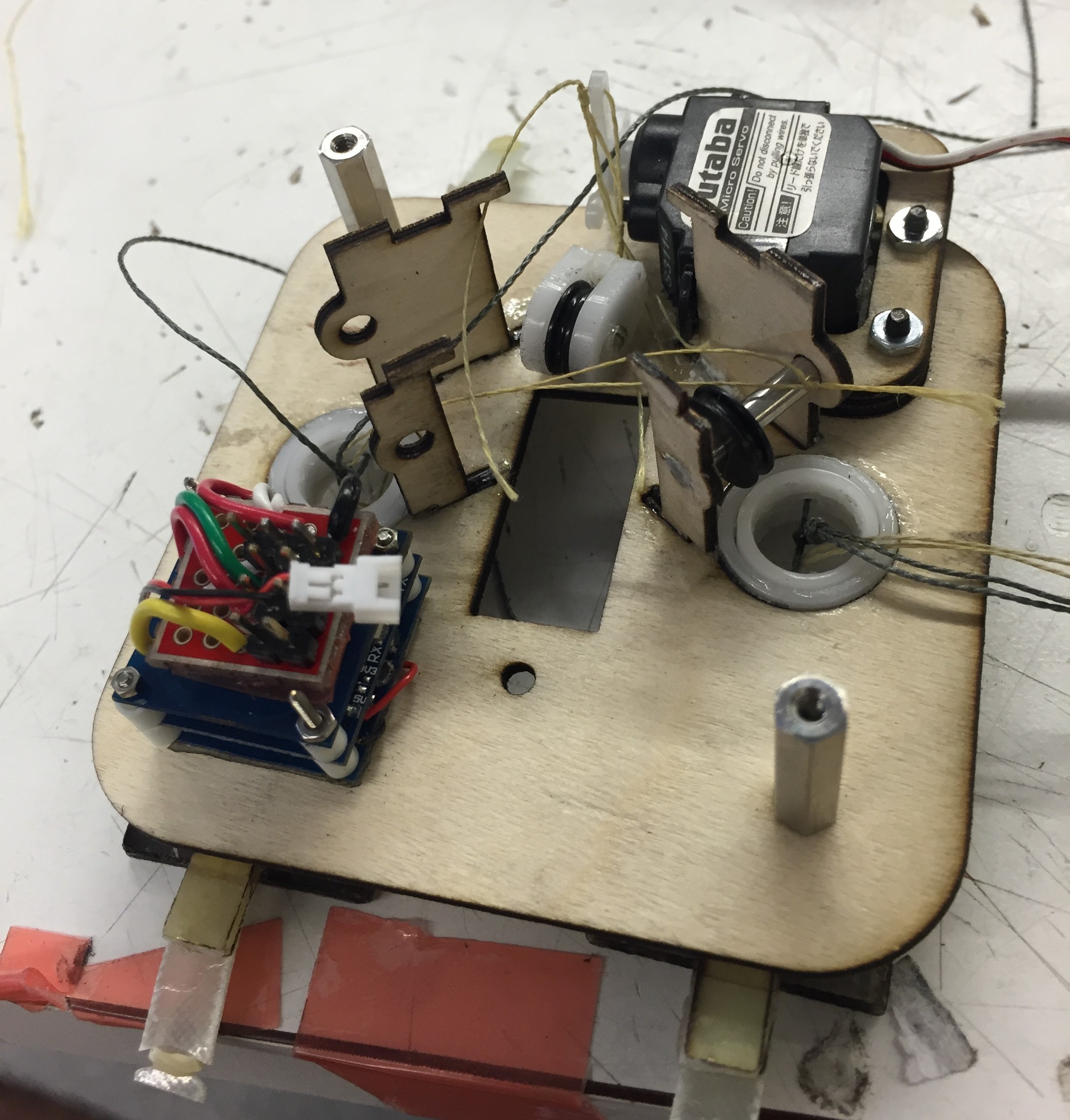
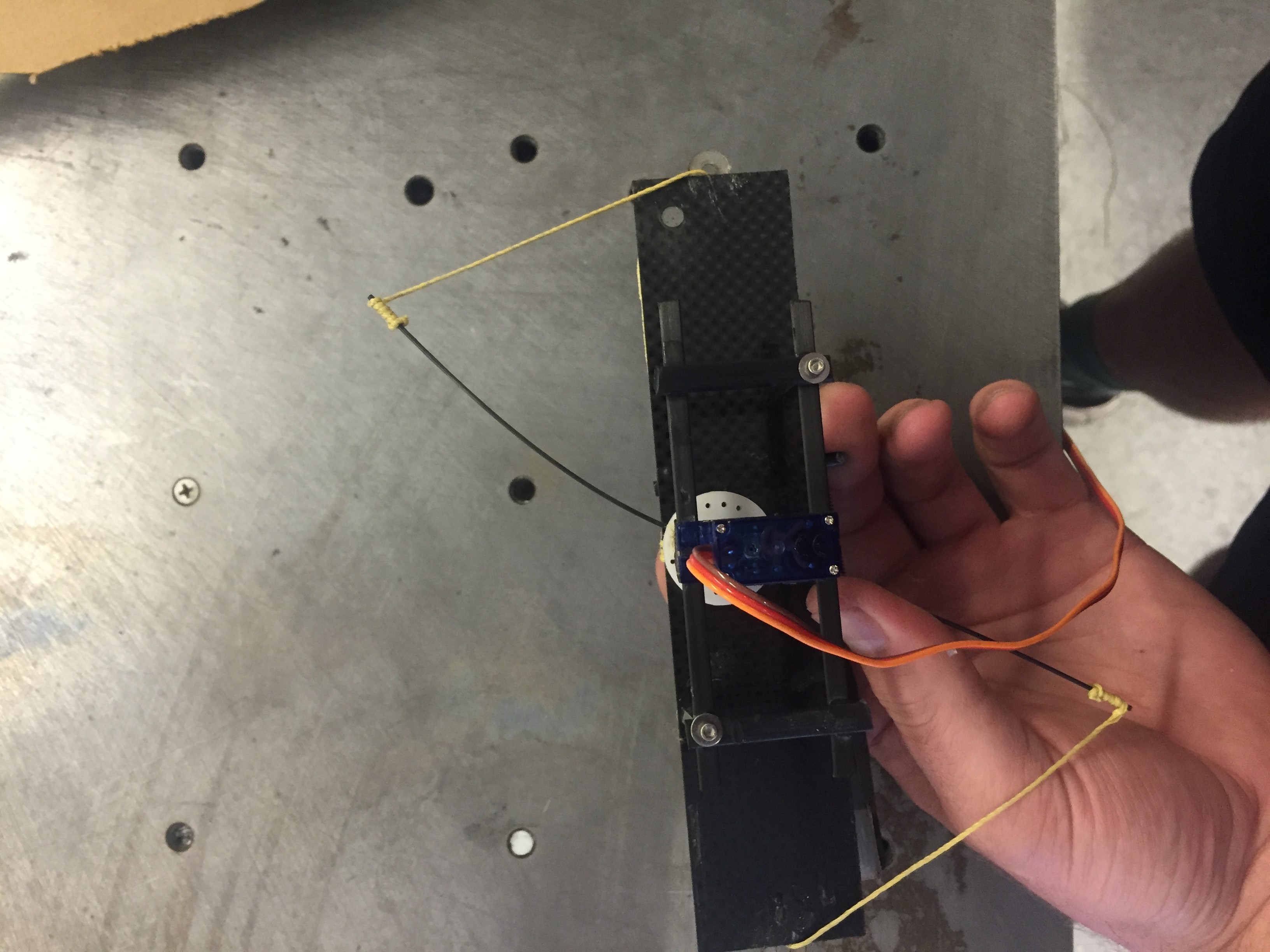
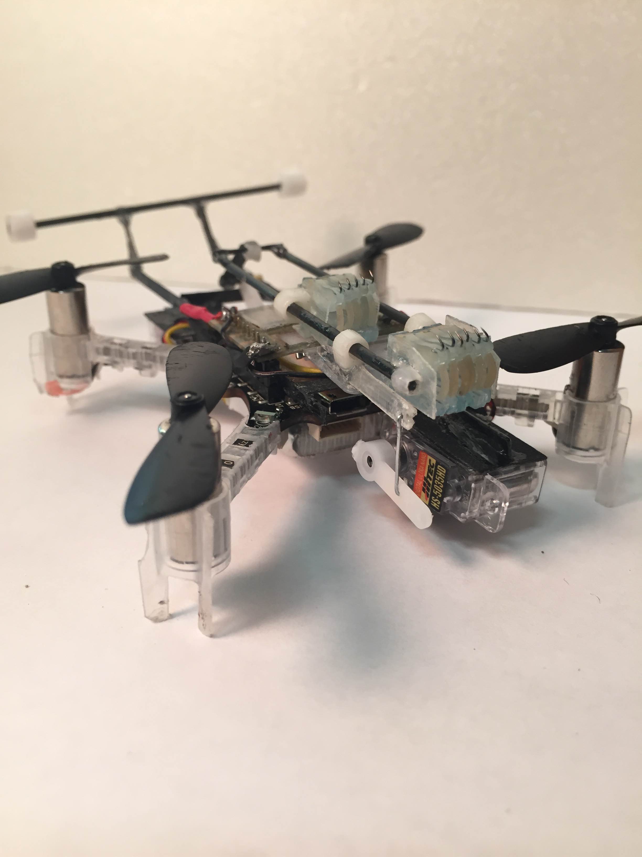
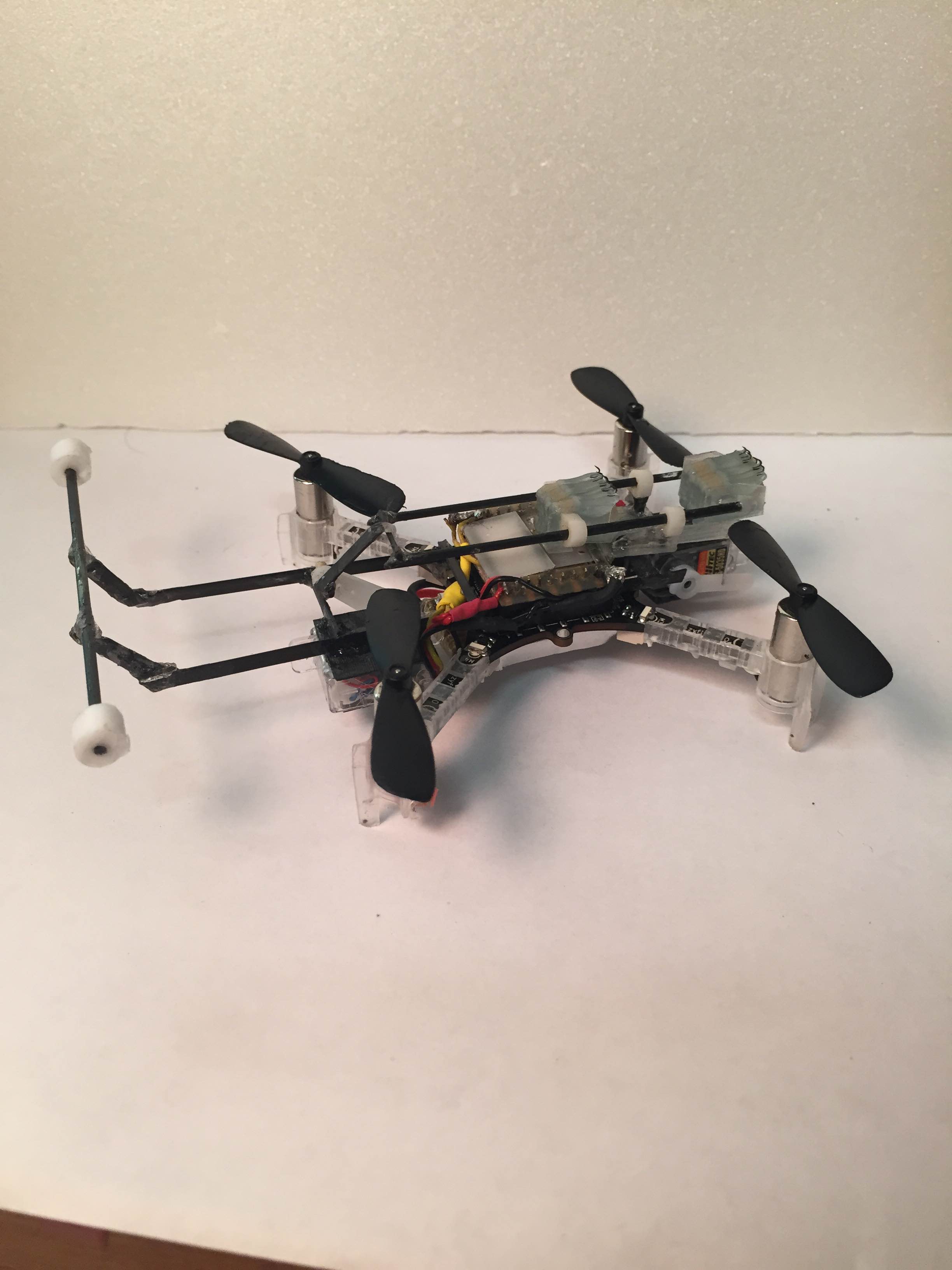
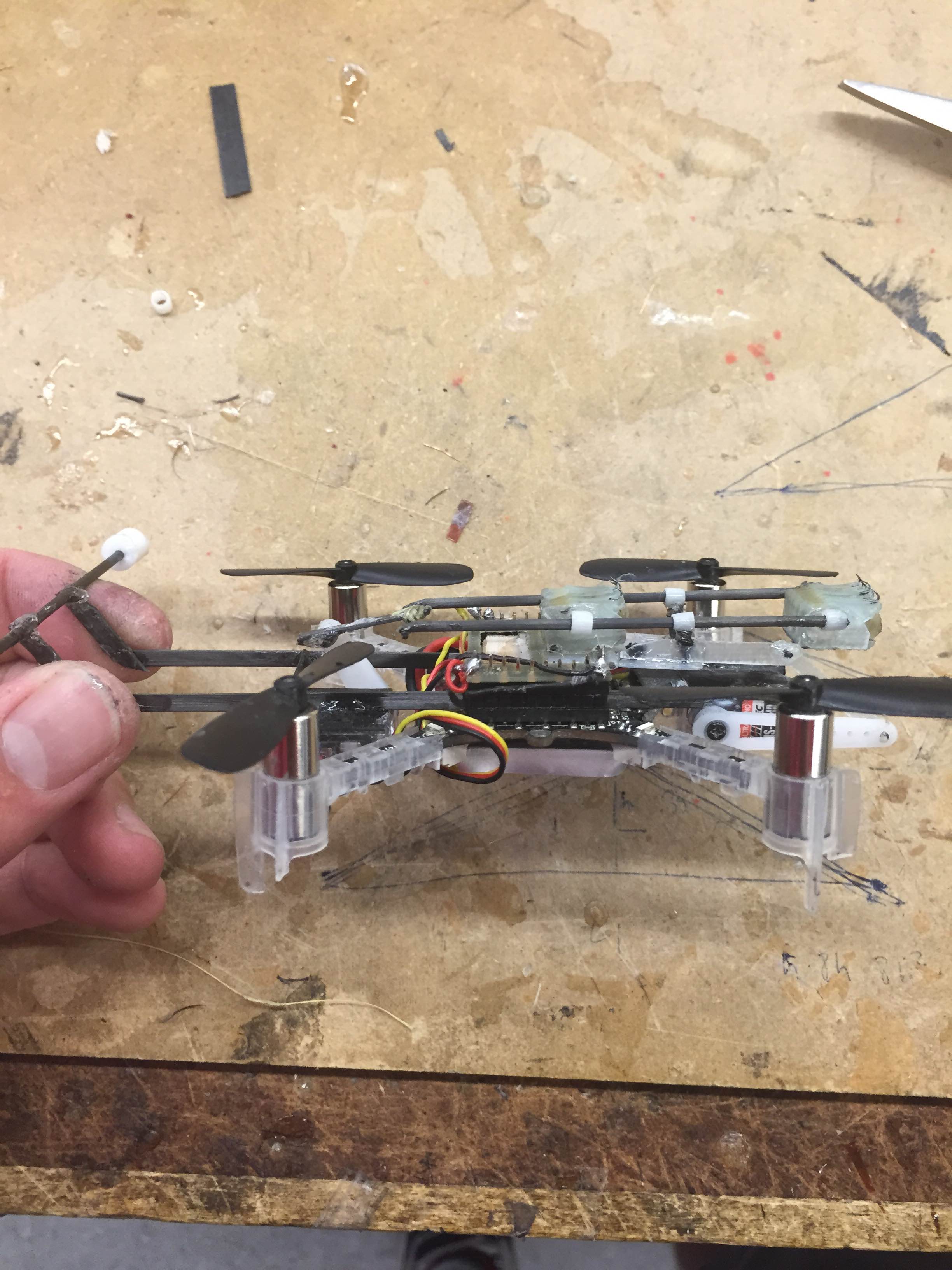
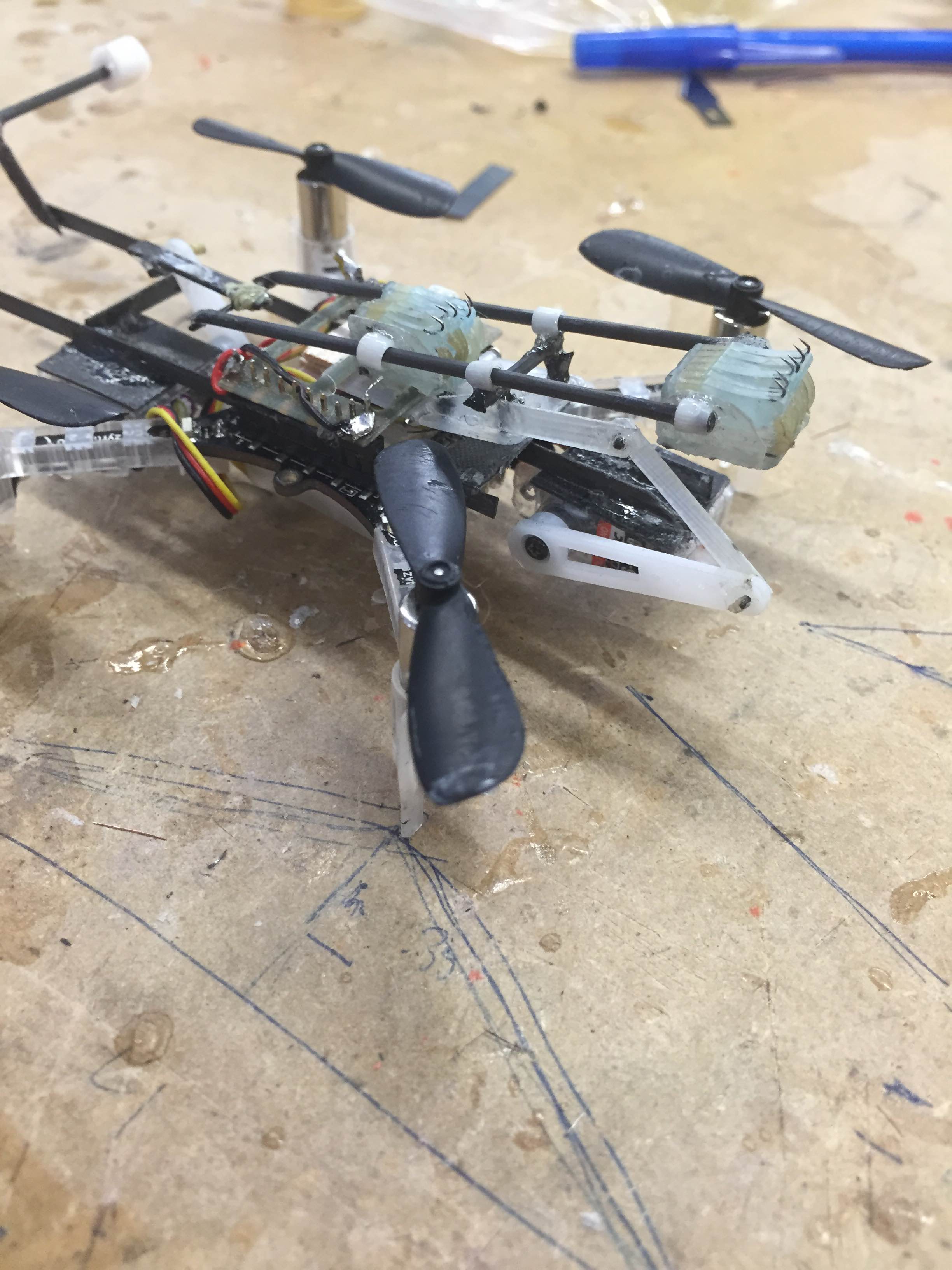
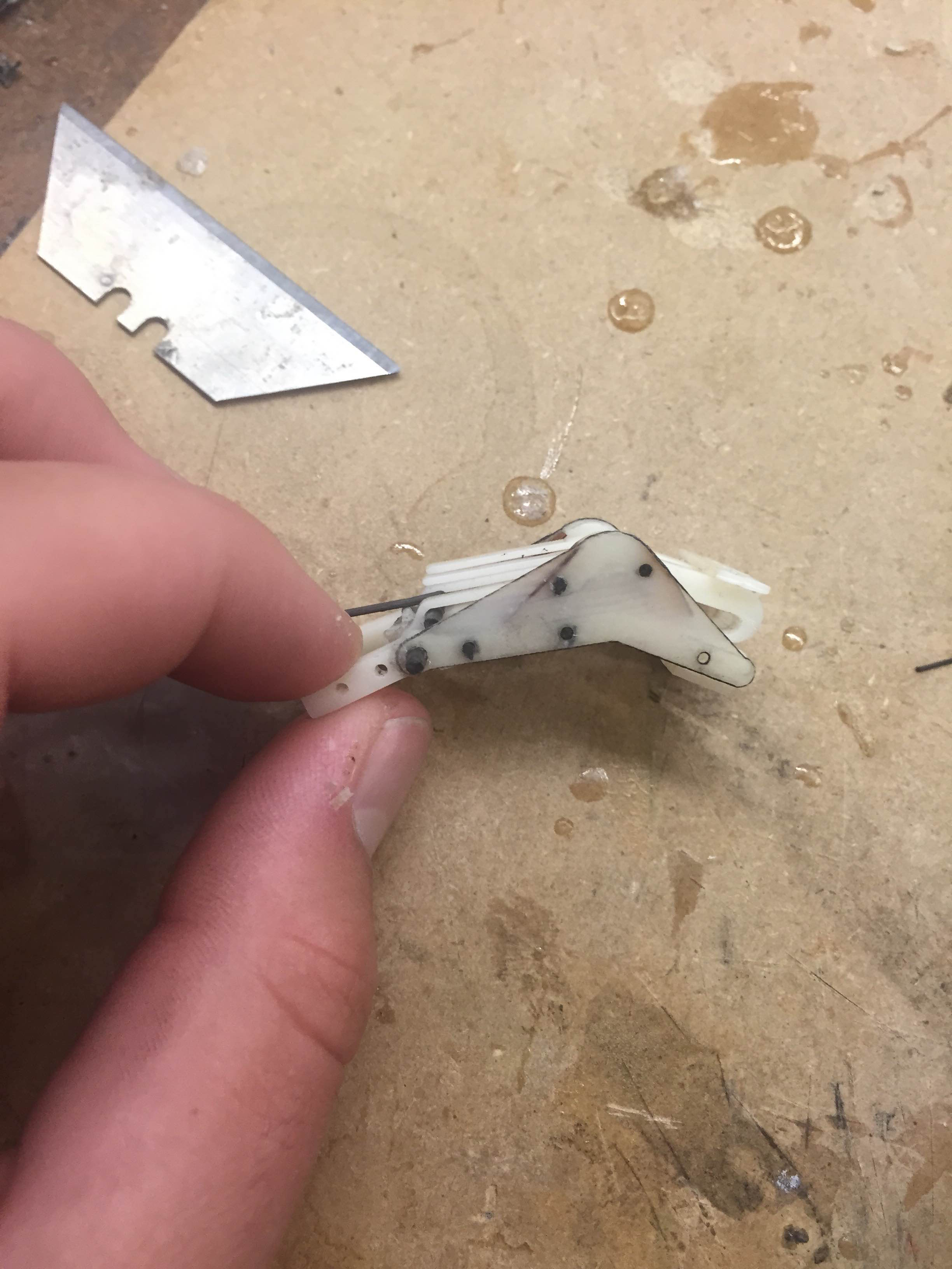
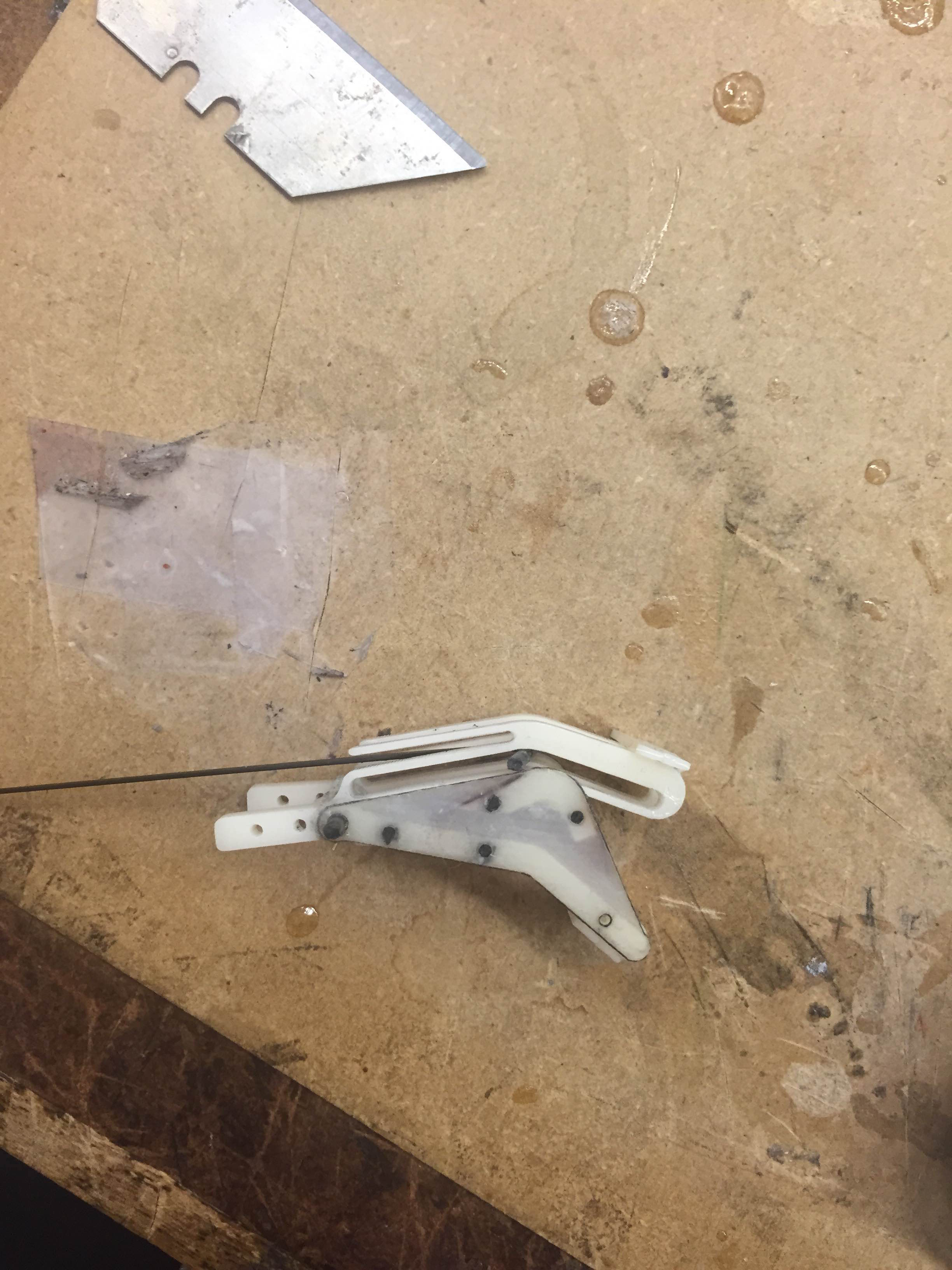
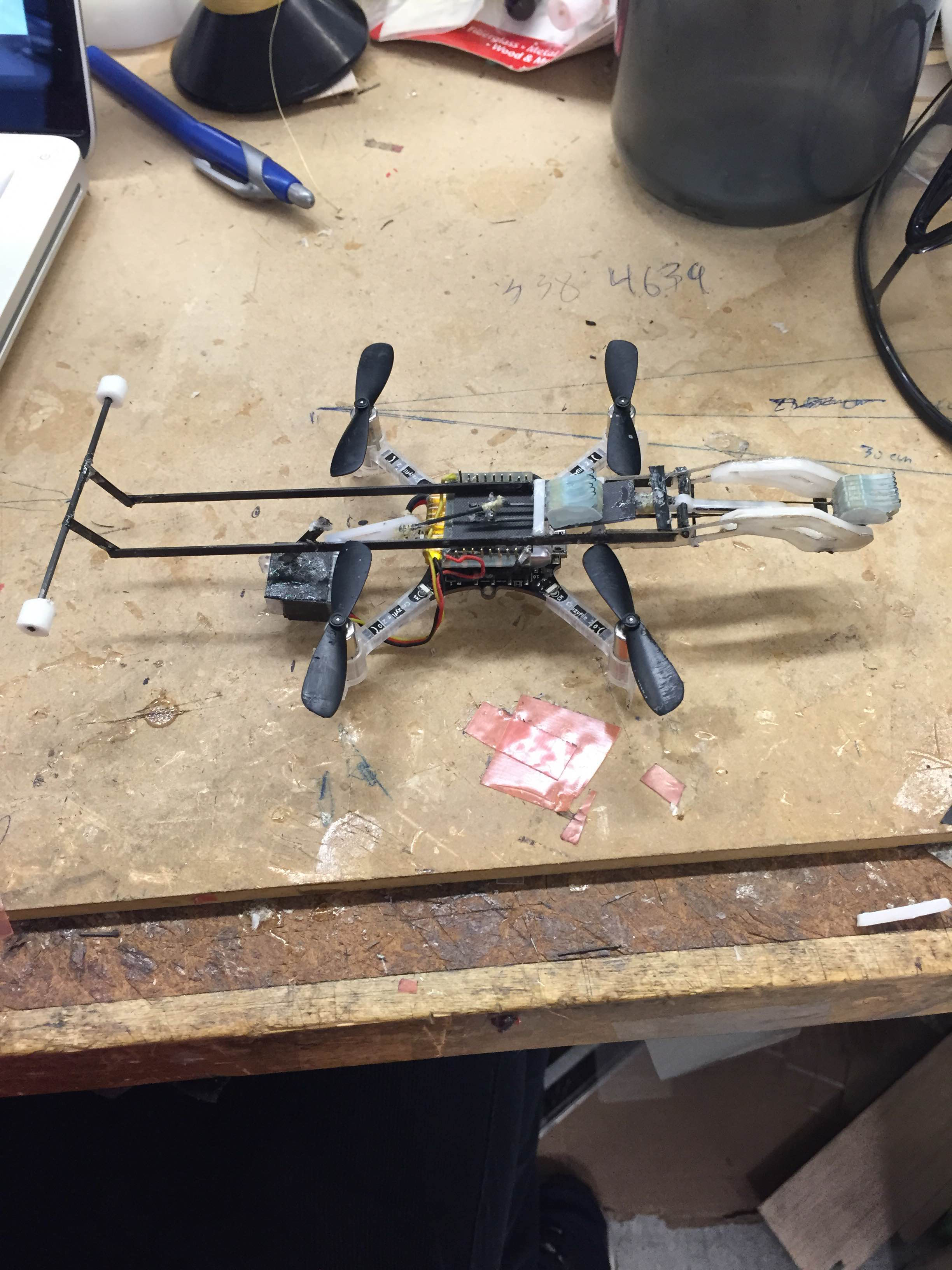
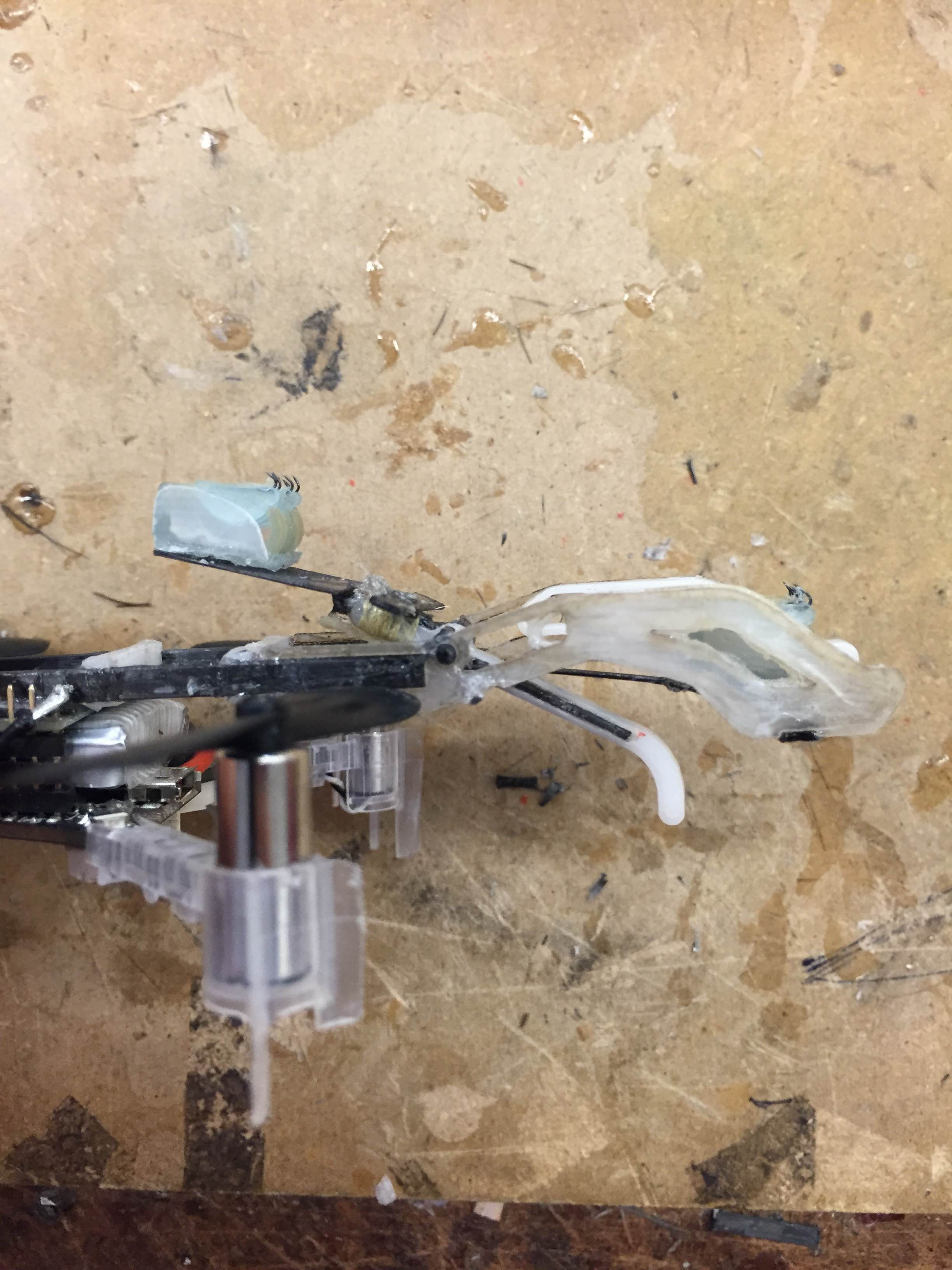
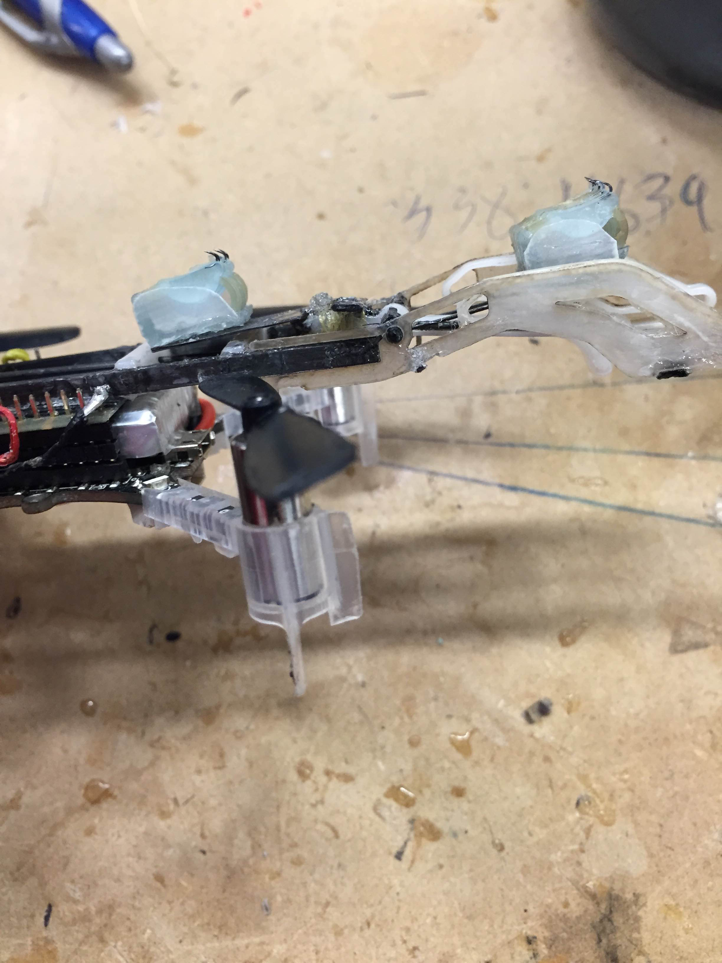
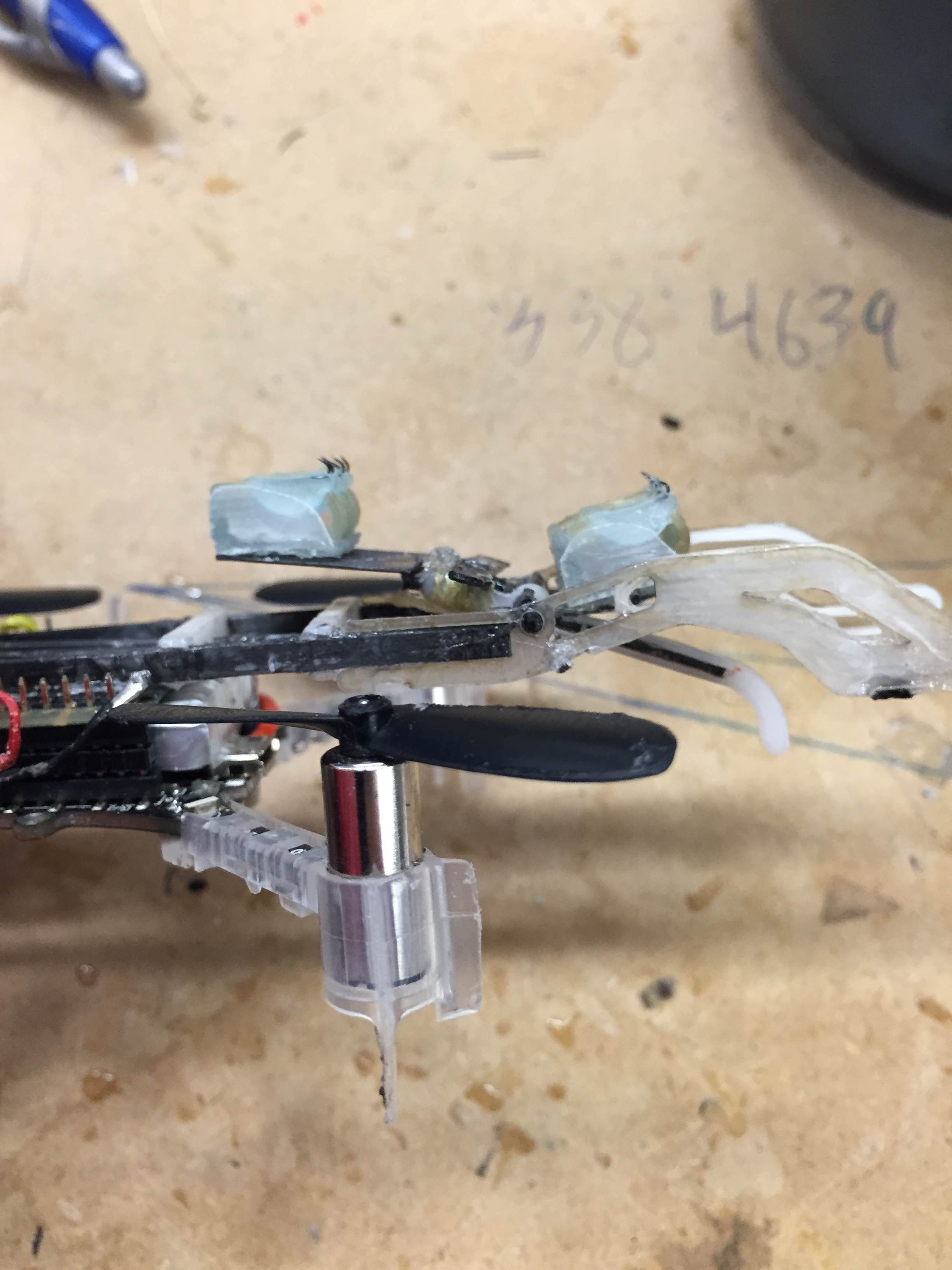
I spent today designing and implementing a compliant wrist for the gripper. My quickly designed, proof-of-concept wrist was very promising. I threw it around on the conference room table at the end of the day and had great results. The new wrist allowed the gripper to come in at angles of around 30 degrees and adjust to grab a glass slide I was holding. The wrist also absorbed extra angular momentum of from the free floating body, which helped prevent early detachment. I'll fine tune the wrist tomorrow and try to get some cool videos.
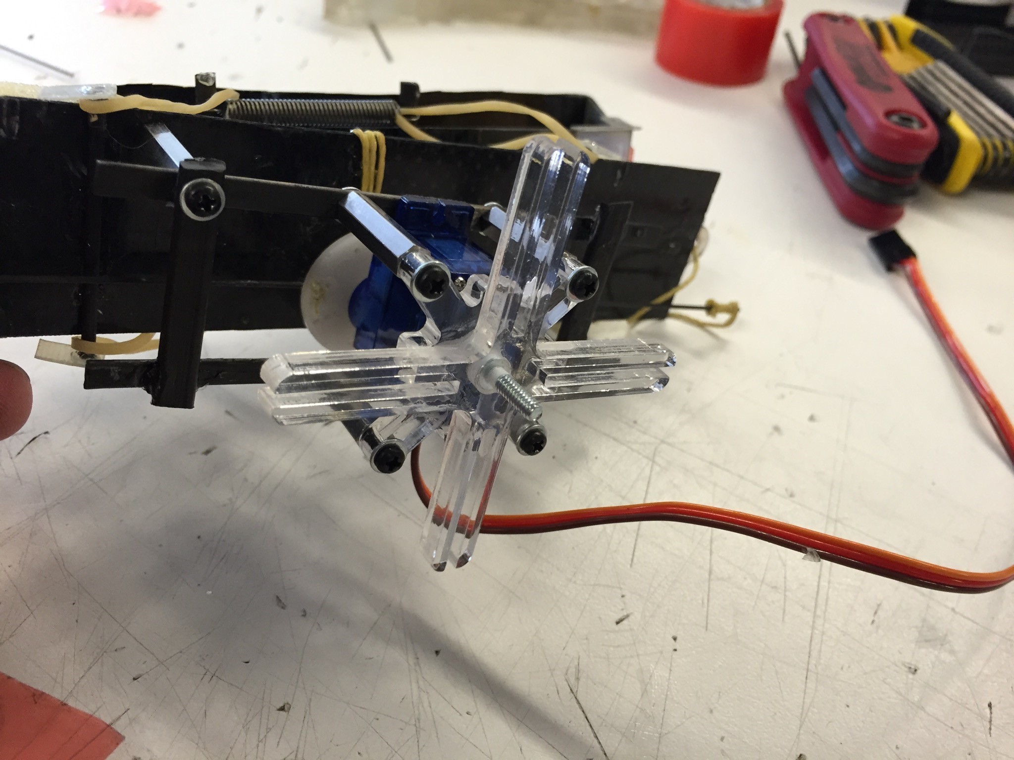
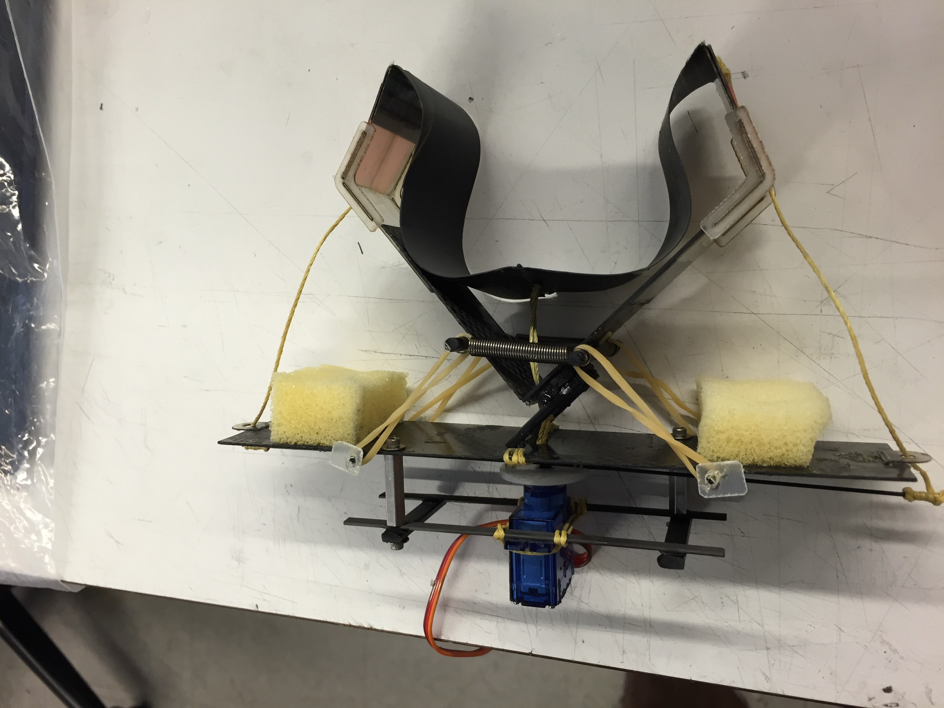
Free flier robot with compliant wrist and gripper. The wrist uses a shoulder bolt as a pin joint and rubber bands to provide resistance to moments.
Wednesday, August 17
I came in this morning and tuned the gripper's grasping threshold for a while. I found it interesting but unsurprising that the time of flight sensor reads different values off of different surfaces, so for our experiments we'll have to use a consistent surface.
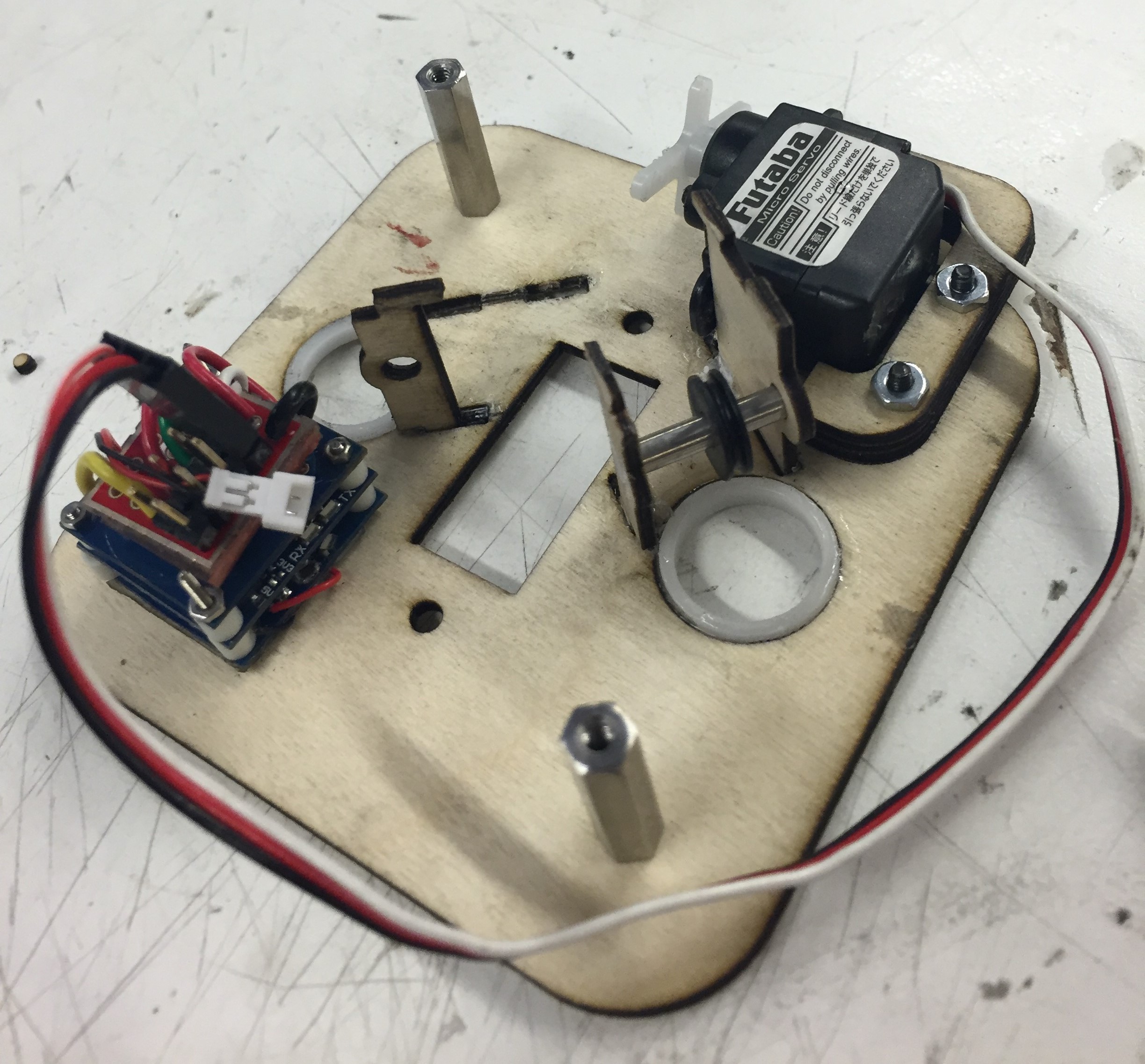
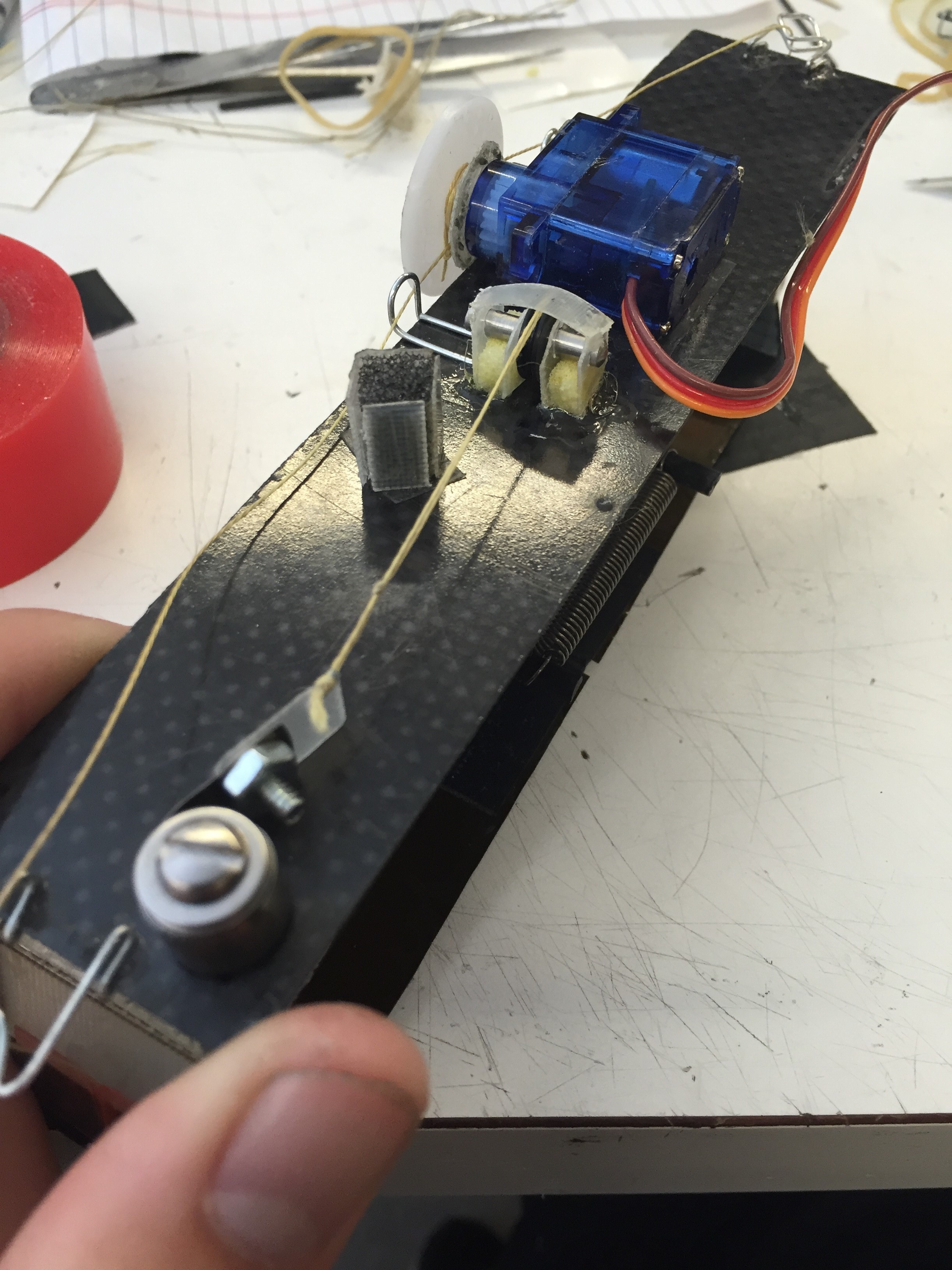
Close up of the finished gripper
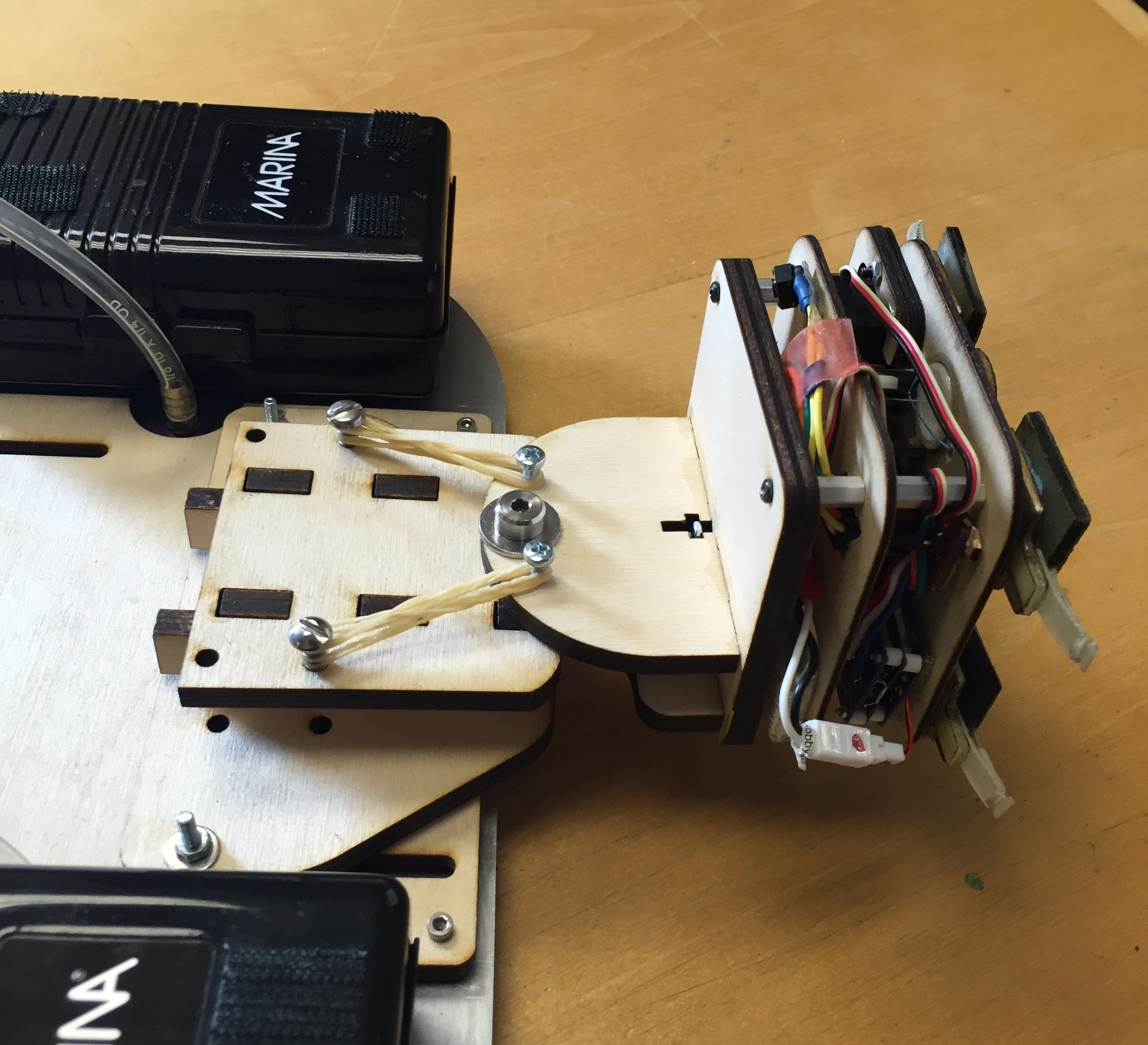
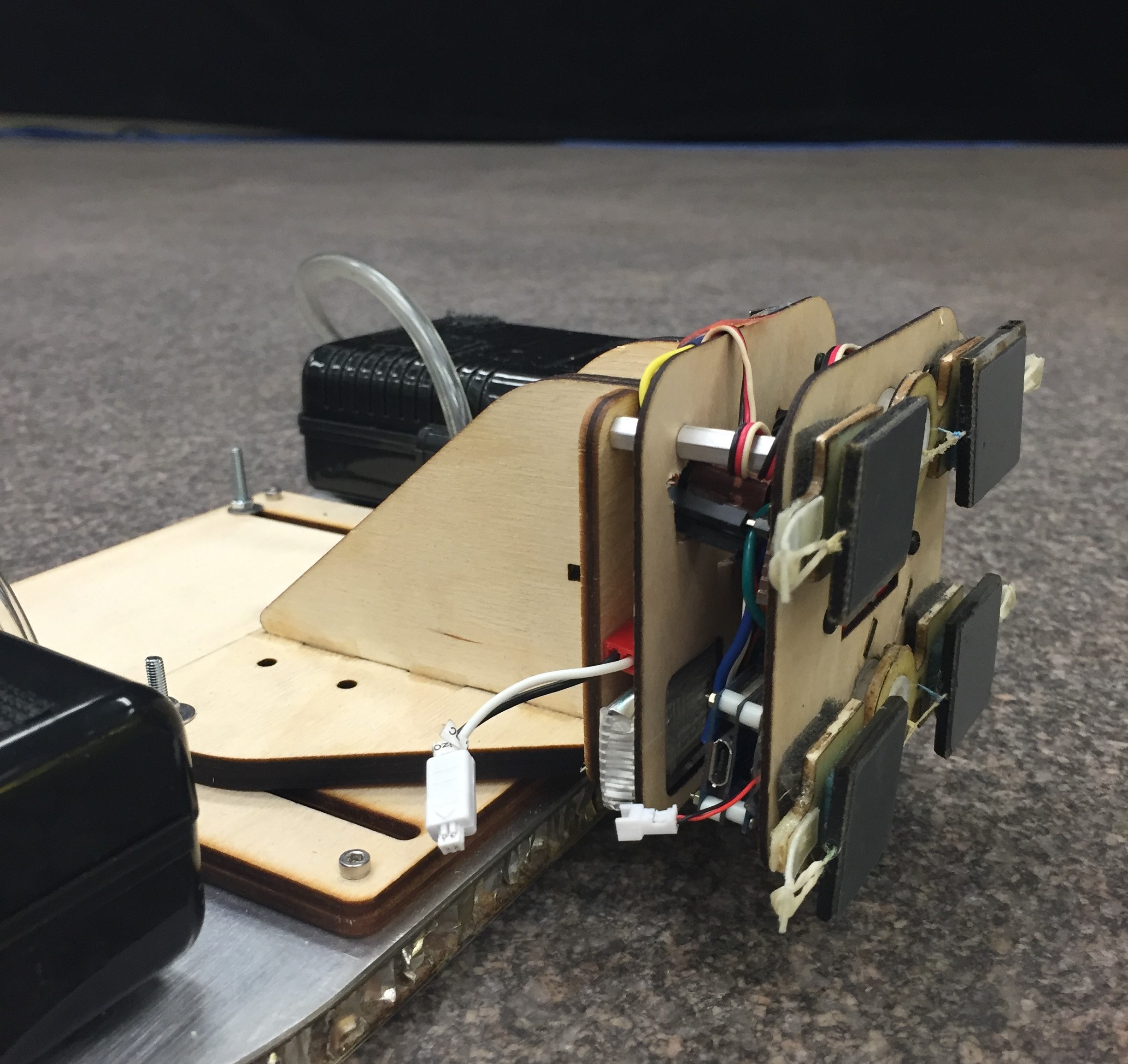
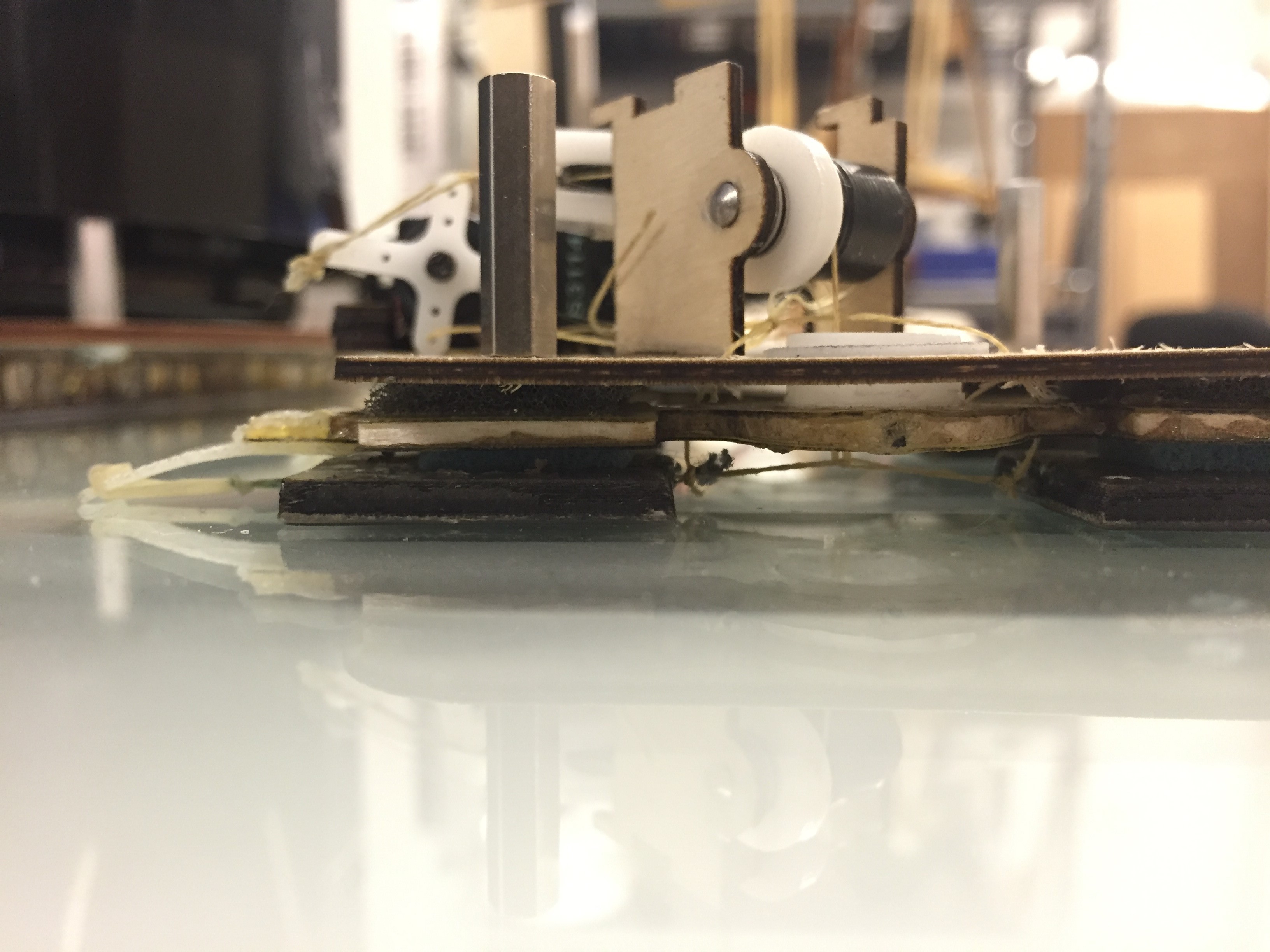
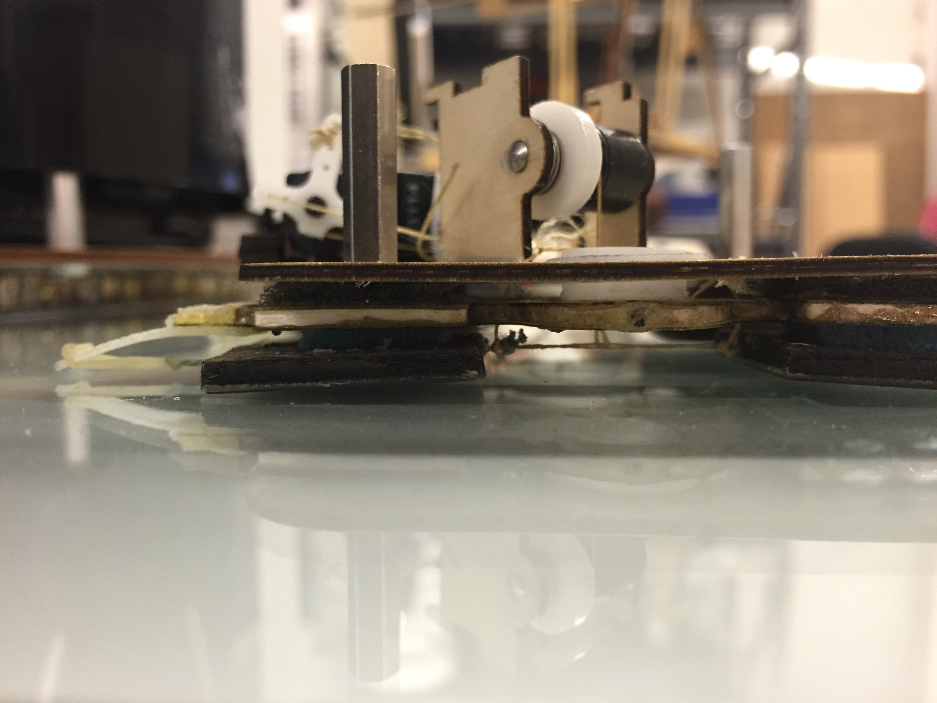
In the afternoon, I set up two of the small free-flying air bearing pads and successfully perched a bunch of times on the granite table in Durand. I also revamped some of the UPenn Gripper CAD for Hao to include in our quarterly MAST report, so I got to briefly revisit that project and CAD some more parts.
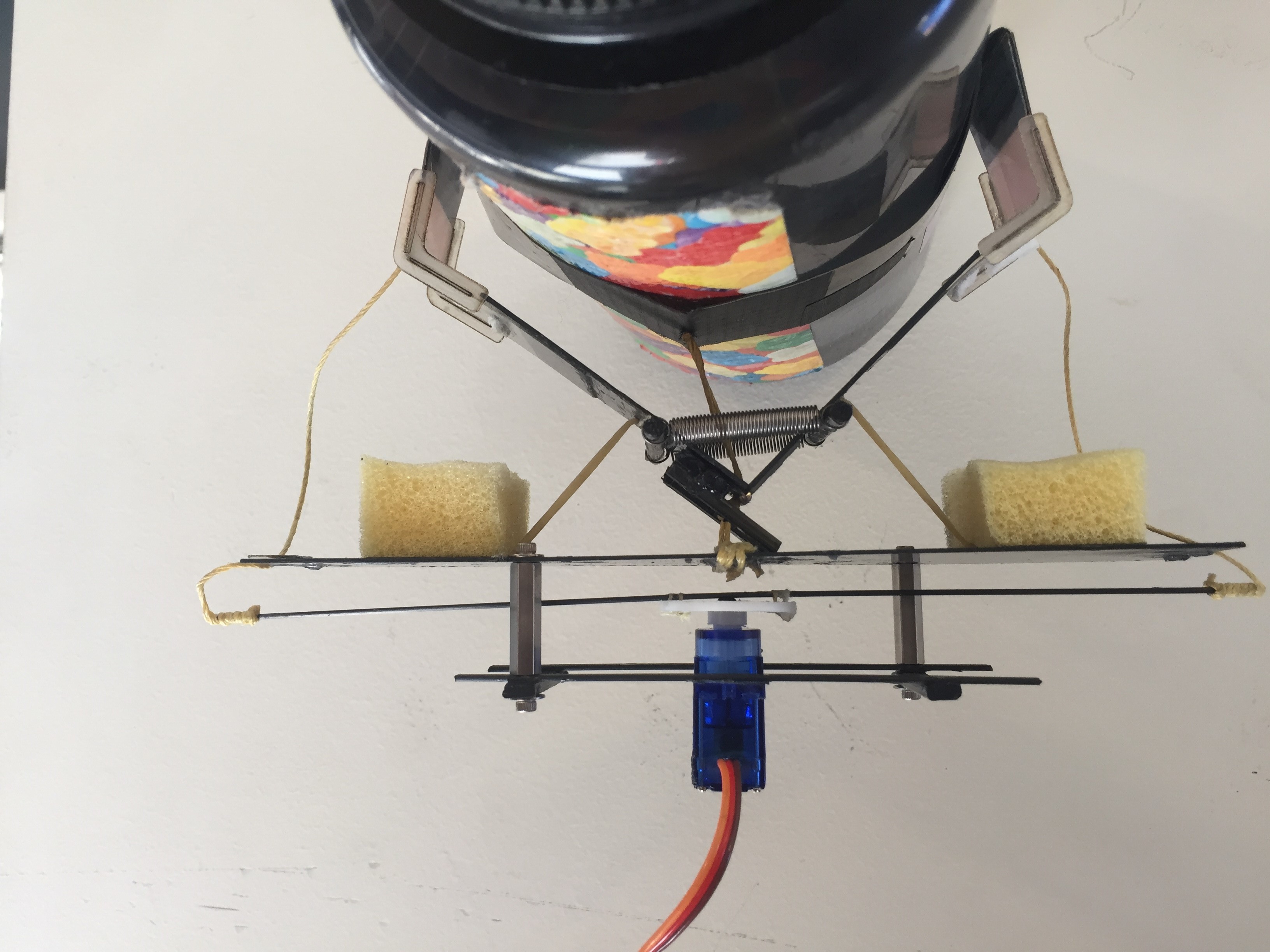
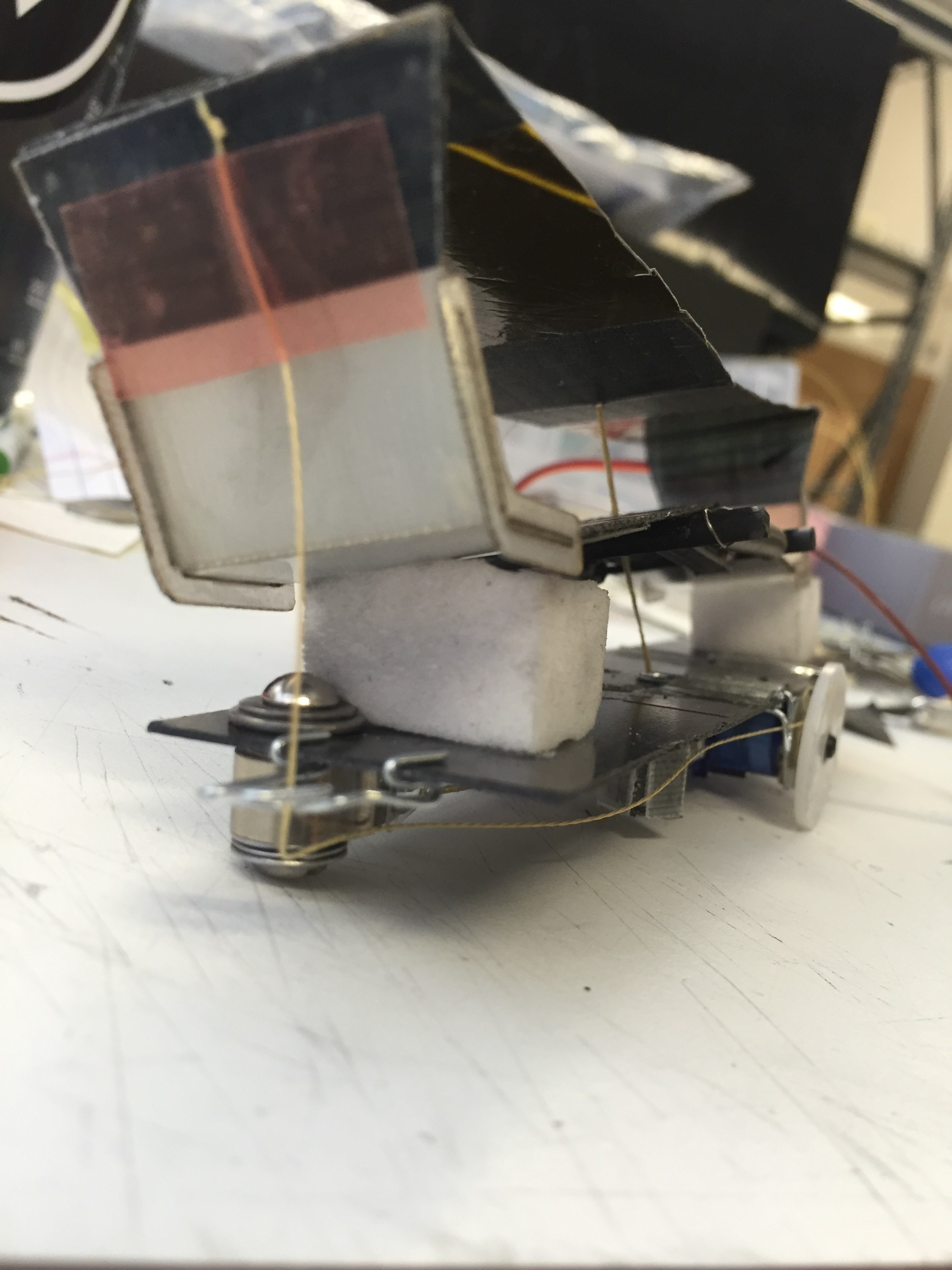
A successful perch on the free flier table.
Tuesday, August 16
I had a long day today. After figuring out my button in the morning, I had an incredibly difficult time getting the Tinyduino to run on battery power. Using a 3.7v LiPo, I was able to run the microprocessor but suffered a huge voltage drop (down to ~1.5 V) once I plugged in the protoboard connected to the servo and ToF sensor. I spent a ton of time looking for a faulty solder joint or short in my electronics, but couldn't find anything. In the process I ended up slowly and carefully re-doing my solder connections to a fresh protoboard, so I shouldn't have anymore issues there.
I started to suspect that somehow, the Tinyduino was limiting the current output while on battery power but not when connected to +5V USB. The other option was that my battery had too low a discharge rate, but since these are the same batteries that power CrazyFlie, I felt that highly unlikely. Eventually I tried running the servo off of the motor controller Tinyshield, which would allow me run the motors off a second battery and on a higher current line. I don't know exactly what happened, but I ended up frying the Tinyduino processor board. It was about 8:30, so I went home for dinner and a hot shower and to regroup.
I got back around 10pm and found a replacement Tinyduino processor board. I connected it all together and put my old program to confirm I hadn't damaged any of the other electronics. Eventually, I tried switching to battery power, and the board just worked. I was even using the same battery, so my guess is the previous processor board (now deceased) had some defect. Anyways, I finished up around midnight and headed home.
Monday, August 15
I had a great, productive morning implementing the state machine and tuning the servo positions and proximity threshold for robust grasping and release. I took a good half hour shaking out the cobwebs to sure I write clean, decomposed code that represents the structure of my state machine. I'm going to make a nice, clear diagram of the state machine to put on my SURI poster, which I'll have to get working on later this week.
After lunch I tried to add a button as a simple interrupt to disengage the gripper and turn off the state machine for a bit. I ran into some of the same solder/connectivity issues I had yesterday, so I'm beginning to think the Tinyduino protoboards aren't super robust. Soldering at lower temperatures helped, but I still had some issues by the end of the day. I also talked to Matt and got a solid picture of our endgame for this gripper. Hopefully I can get it on a freeflier table soon.
Week 8
Friday, August 12
Today I finally vanquished the electromechanical demons that have been plaguing this gripper project. I installed a replacement servo this morning. I was lucky to find an exact replacement so I didn't have to re-string my load and release tendons or design a new mounting bracket. Once that was complete, I had a lot of issues initializing the rangefinder, which uses the I2C protocol. I ended up looking through and running Bessies code, which was directly adapted from the Sparkfun example code, but still failed to initialize the sensor. I also read through Ian's blog from last summer, since I recalled him having some Tinyduino/I2C issues, but it didn't help me much.
Eventually, using a multimeter for connectivity tests, I found that one of my solder connections from the from the wires to the I2C pin on the Tinyshield was bad. While the connection looked good on both sides, when I actually found the individual pin on the stack and tested it, there was no connection. The copper ring in the thru-hole was actually missing, either burned out or destroyed by a clumsy soldering job. Having to go through the Tinyduino stack and find this error took forever, and was pretty frustrating.
Anyways, I was finally able to run the simple code and tune the sensor threshold and servo positions to ballpark value. At the end of the day, I perched the gripper directly on the glass windowpane in the lab, and decided to call it a day. I will have to fine-tune the gripper's behavior on Monday.
Thursday, August 11
After perching meeting yesterday morning, the past two days have blurred together into an unending stream of electromechanical debugging. Despite feeling really good about the simple code I wrote yesterday, I was unable to successfully command the servo to certain positions. It would work sporadically, but most of the time the servo would not respond to the commanded position. Since I had changed very little in the hardware or software from the previous prototype, I focused on the one area I had altered: the Tinyduino protoshield and the stripboard that I resoldered.
I spent most of yesterday afternoon laying down soldering the pins together correctly and focusing on cleanliness to no avail. This morning I focused my efforts on the software, which also proved futile. Even stripping the already simple arduino code to a single "analogWrite()" command to send a PWM signal failed. Eventually I discovered that the servo itself was broken which I did not test since I pulled it directly from the last prototype, where it worked fine. I will need to find a new servo to replace it tomorrow.
I also spent a good amount of time today helping disassemble, clean, and reassemble the Ford Pinto transmissions for ME112. The combination of being outside in the sun, getting my hands dirty and covered in grease, and playing around with some interesting mechanical components was a welcome break from a thoroughly frustrating debugging process. I did suffer a bit of a sunburn though, but that's my own fault for not paying attention to keeping to the shade
Tuesday, August 9
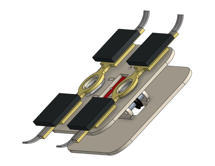
I am now mechanically finished with the gripper. I reattached the release tendons and re-routed them through some small delrin spacers found. This keeps the tendons out of the way when slack, and creates more travel when the servo arm is pulled. I then spent a while re-stringing the load tendon pulley, since balancing the tensions so there is an "active," a "neutral," and a "released" state is crucial for the desired use.
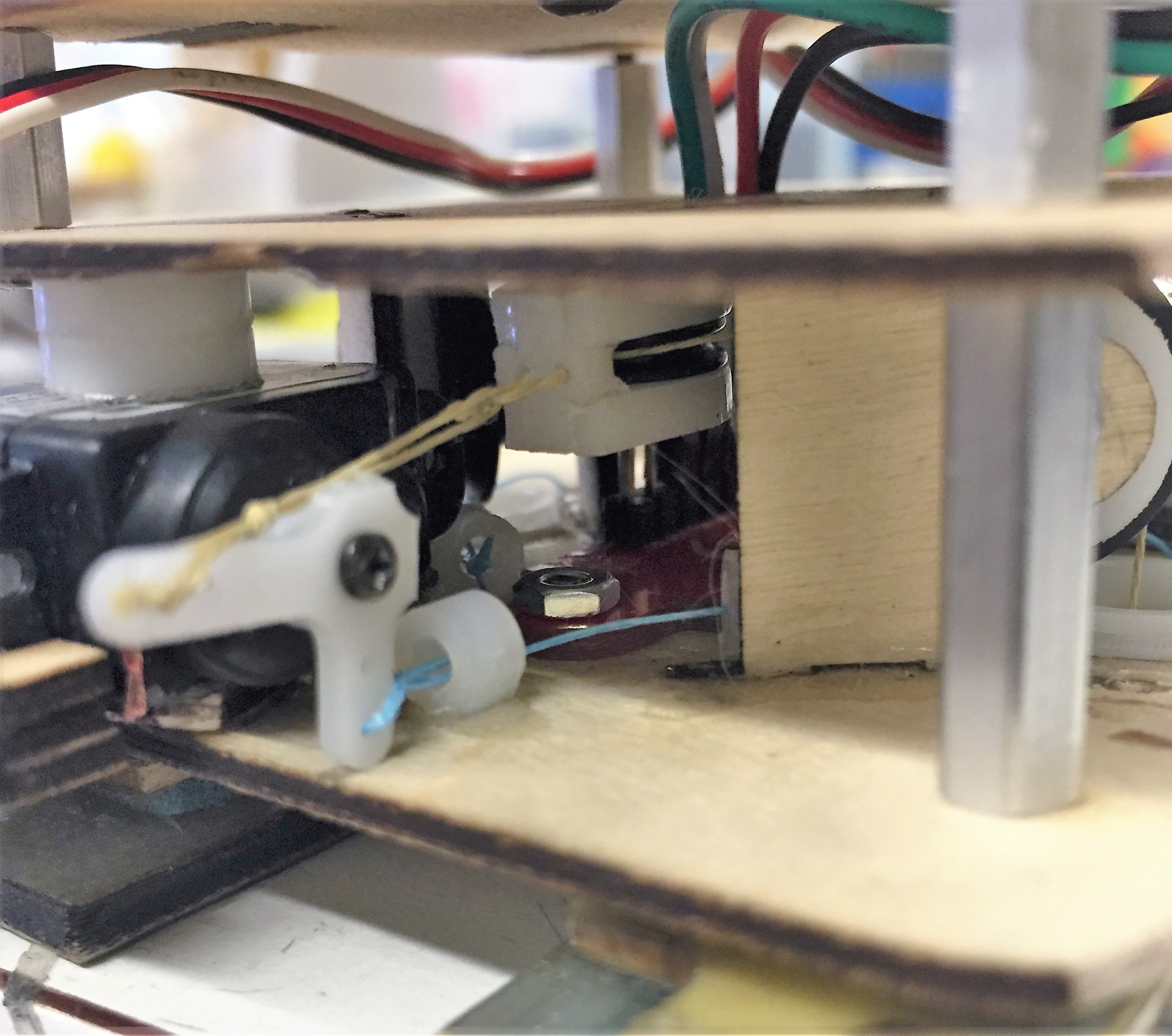
Close-up of the small spacers that guide the release (blue) tendon
I also took the ToF sensor off of Bessie's now-defunct curved gripper prototype, and wired it to the stripboard atop my Tinyduino. I had to do a bit of quick soldering work to change which holes on the stripboard went to certain Tinyduino pins. I also had to cut a small hole in the top plywood plate for wires to go through from the sensor, but it didn't affect the structural integrity significantly.
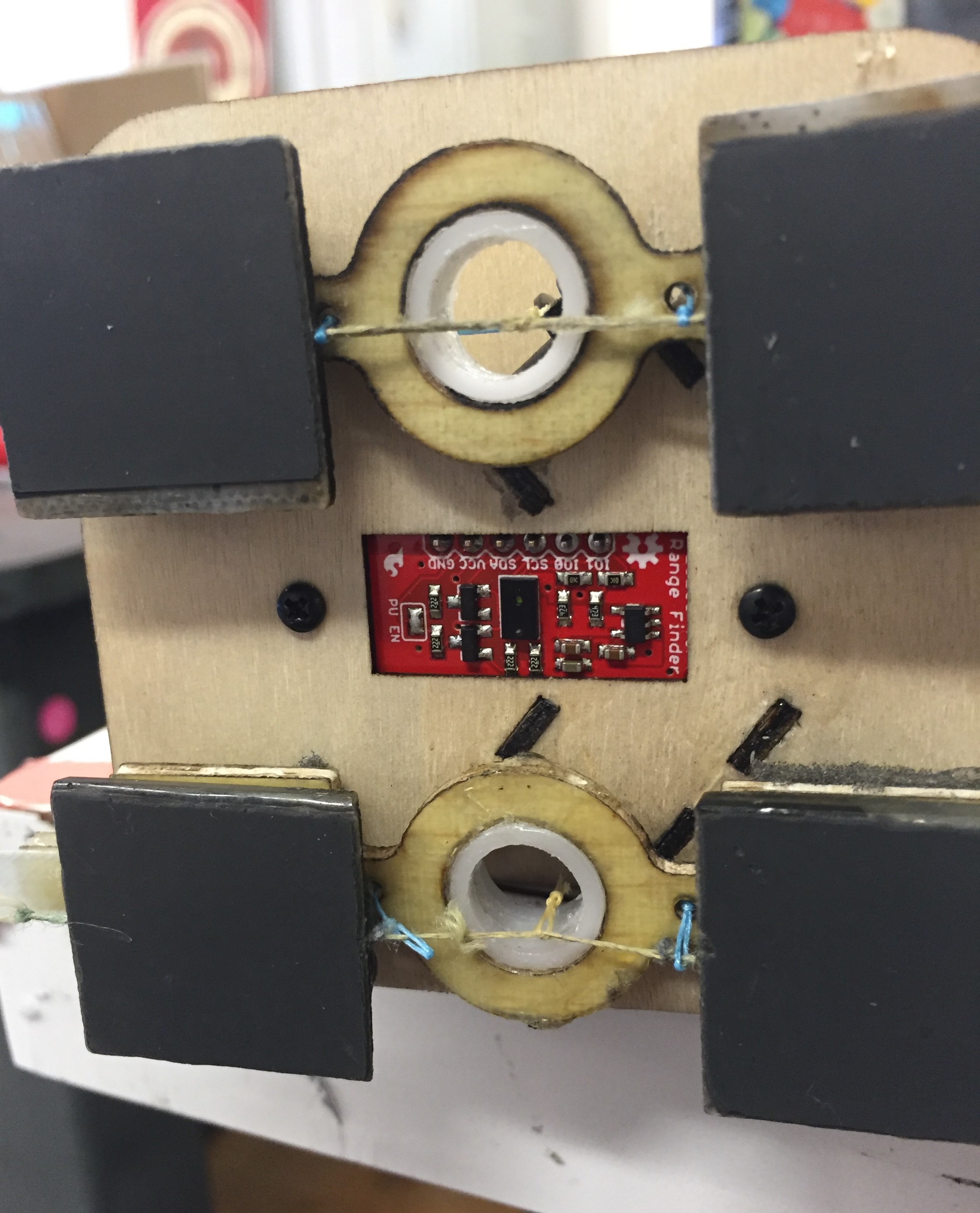
The sensor in place, facing any perching targets.
I ran some final pull tests towards the end of the day, and the gripper was consistently pulling between 13.5 and 14.5N, which means that my load sharing mechanism works well since each pair of adhesive pads can only hold a little over 7N. I will write some code tomorrow to begin sensing when objects are grapsed, as well as build a simple state machine.
Monday, August 8
I spent the morning finalizing and cutting the mounting plate for the gripper. It is now basically finished save for the sensor, so I might make a deal with Bessie to snag the sensor from her project since I don't think it is operational any longer. There are a few details I can work out to make it function a bit cleaner, so I can spend this otherwise idle time working to clean up some of the bugs.
The completed attachment piece, which will interface with the free-flier's frame.
In the afternoon, I met with Alina, an undergrad working in Marco Pavone's lab who is designing and assembling both the host free flier and the target free flier. I confirmed that gripper and its mount would fit the mounting plate and align with the target, so I turned my focus to improving the load-sharing mechanism within the gripper. I had been having some issues with the load tendons slipping off the pulleys, so I tried cutting some large diameter washers from fiberglass, but these proved ineffective. I then switched out the pulleys for some larger ones that barely fit underneath the top plate, and they proved to be a major upgrade over the smaller ones. The larger pulleys better aligned the load tendon with the center of the adhesive tile pair, and the tight fit between the pulley's edge and the top plate makes it nearly impossible for the string to fall off the pulley. The larger diameter also meant more surface contact, and once I removed a few washers to account for the wider pulley, the whole shaft had significantly lower rolling friction. In the process, I did destroy the release tendon, so I will have to rework those early tomorrow.
The new pulley installed. Note the tight clearance between the pulley and plywood plate above.
Week 7
Friday, August 5
Lab meeting this morning was incredibly interesting, with French visitor Idriss Aberkane giving a fascinating talk about the micro- and macroeconomic implications of the knowledge economy. He talked about the currency of knowledge, which is attention*time (At) and how it is an economy that all people in birth have the same purchasing power. He also specifically focused on why bio-inspired design is so valuable, because nature has had "a four billion year R&D cycle" to develop things mankind still cannot. I found the talk very thought-provoking, and very inspiring, since it gave larger context to the work done by the BDML and by engineers as a whole.
In the afternoon, I got CAD files for the free flier attachment point from Andrew, so I set out to design a robust attachment method for the gripper. I'm a bit frustrated that my sensor has not arrived in the mail yet, but there's not much I can do about that. With any luck, it will arrive soon and I can have a fully electromechanically functioning gripper. I performed some more pull-off tests, and the last thing I will have to do is going to be creating a pulley guard so that the load tendon doesn't slip off of the pulley when unloaded.
Thursday, August 4
I continued assembling the gripper today, and I am now done with the load sharing pulley system and the release tendons. I had a pretty difficult time tensioning all the necessary tendons so that it would work, but my preliminary tests at the end of the day showed clean grasping, releasing, and what felt like good load sharing. I will have to devise a more complex test to actually prove load sharing is occuring, but the pulley system appears to be working smoothly and the gripper felt good in various pull off tests I ran. I'm pretty excited to see it work once the sensor comes in and I set up the Tinyduino again.
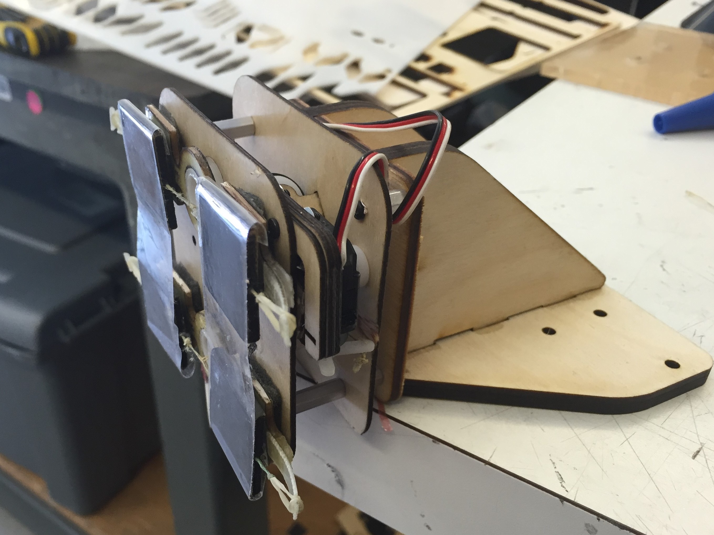
Finished load and release tendon systems
Left: Gripper engaged. Right: Release tendon engaged, pads peeling. Note servo arm position in background.
I also joined Matt for his meeting with Andrew and Roshena, students in Prof Pavone's lab. I got a better idea of what they want out of the project, and got some mechanical constraints. Apparently I will have to fit the gripper into a 3" vertical window, so I may have to shave a few millimeters off the sides.
Wednesday, August 3
I had a Skype call with Justin and Hao this morning with the first test results from the UPenn gripper. Justin shared a bunch of videos with me of successful and unsuccessful perch attempts. The gripper did not do well when not aligned, and performed alright when aligned. They were using a pipe that was 8cm in diameter, which is a bit small, so a larger ~10-12 cm pipe will provide an easier perching target. I will also be rebuilding the lower stage, which incorporated the release servo, in order to be more compact. I will likely end up using two small servos rather than a single larger one to reset the mechanism. Since this lower module also holds the quadrotor attachment point, I might also incorporate a compliant wrist to aid in perching on off-center targets.
Gripper assembly progress today.
In the afternoon, the McMaster order arrived and I began assembling the gripper in a frenzy. I had to leave to go cook for my housemates before I could run the main tenonds through the structure, but so far it is coming along nicely.
Tuesday, August 2
I did not have a very productive day. I ordered my parts (and more Loctite) from McMaster and the ToF sensor from Sparkfun this morning, so at least the McMaster stuff should arrive tomorrow. I figured I could help Aaron take some more hexapedal gait data with my downtime, but they busted a motor early in the day so the robot was out of commission. I redesigned a pulley housing and re-cut some parts, and double checked some of the fits. I decided to head home early around 4:30 and run some errands so I can stay later on Thursday evening. Once the McMaster order arrives, I should be good to go on assembling the full gripper tomorrow afternoon. I also might have to do some work revisiting the UPenn gripper tomorrow, since we will be talking with Justin over skype in the morning.
Monday, August 1
I finished CADing the loadsharing level of the gripper, and laser cut some of the parts. The laser in the TLTL is having a bit of a tough time lately, and I had to re-CAD and re-cut some of the tab attachments when the kerf was way more extreme than expected. I'll need to return tomorrow to cut a few more, and I'll have to order some more pulleys and a sensor, but overall, the gripper is coming together.
Final CAD Shot.
Started assembly before running out of superglue.
I also spent a good amount of time today updating the MERL BBQ page on the basics of cooking with coals outside at Gibbons Grove. I realized that this year, we were fortunate to have a SURI with significant grilling experience (myself), and that cooking meat is somewhat difficult if you don't know what you're doing, so I added some basic grilling guidelines. I also added some budget/purchasing knowledged gained from two consecutive BBQs. I'll add a section on how to use the brand tomorrow, or maybe ask Aaron to do so.
Week 6
Friday, July 29
As I type this, I reek of charcoal and my hands stain the keys with soot, but it is all good since our barbecue was a huge success. I drove and picked up ice this morning, and a second bag of charcoal. Bessie and Aaron went and got ice buckets from ME student services, and tables from the d.school while I started preparing the coals. I lit the two grills at 10:10, and put the first chicken breasts on at 10:30. We marinated the chicken overnight in a combination of balsamic vinaigrette and barbecue sauce, which is the Kimes family go-to marinade because it's really cheap, requires little effort, and results in sweet, juicy chicken breast. I finished cooking the first round of chicken on both grills (about 30 breasts) by 11, at which point I had to replenish the coals.
By this time, Aaron and Arul had commenced branding the hamburger buns, which came out really nicely. I'll include some instructions on how to use the brand on the private MERL BBQ page, which I plan on updating in depth this weekend with knowledge gained through two barbecues. Check out Aaron's blog to learn more about the branding project
When people arrived at 11:50, we had about 30 chicken breasts and 30 burgers ready for the crowds. If I could do the barbecue over, I would have tried to get one more grilltop (~15) worth of burgers out before the crowd showed up, but overall we were in pretty good shape. A decent line formed, but it moved fairly quickly, especially after we started cooking hamburgers on both grills. We were able to crank out another 15 burgers every 10 minutes or so by moving quickly on both grills, and the vast majority of people got served by 12:30, with a few people staying for seconds around 12:45 and a group who came late getting the last of the chicken around 12:55. We ended up giving out about 80 burgers, 55 chicken breasts, and all 12 veggie patties.
The last half hour of cooking was slow, since the coals were staring to cool down and we ran out of reinforcements, but I did a thorough job of making sure all meat that I served was cooked well. I didn't even suffer any charred casualties from forgetting to flip a chicken breast on time, though I did singe a lot of the hair off my right hand attempting to "encourage" some cold coals with lighter fluid. Overall, we had exactly the right amount of meat, and we were able to serve everyone with only 5 cooked chicken breasts left over and about 10 frozen patties to donate to next week's group. Although I was a bit concerned at the end when our coals started to cool down, I did a better job managing the cooking than we did last year, and the coal grills at Gibbons Grove are a definite upgrade over the PRL gas grills.
Since I was standing over a flaming grill for three hours straight, I have to give a major shout out to Bessie, Aaron, and Vanessa for setting up the tables, hauling supplies over from MERL kitchen, getting me extra lighter fluid when we ran out, and generally making sure the rest of the barbecue ran well. I got to do something I love-cooking meat-and they enabled me to focus solely on that. I had two chicken breasts and a surplus cheeseburger, and I will say that I did some very good work. The chicken was particularly excellent, and was some of the best I've ever made.
After thoroughly washing my hands, Aaron and I took some more data using Alice's hexapedal robot on the polished concrete floor in the MERL hallway. We found that the robot was pretty skittish on the slick floor, but identified one particularly stable set of gait parameters and took some a nice high-speed video of it.
Thursday, July 28
I spent the morning touching up my CAD for the gripper. I should be ready to cut everything out pretty early on Monday. I want to finish making realistic mates to that the CAD model can behave approximately how the real-life implementation would.
In the afternoon, Aaron and I took data for Alice's hexapedal robot running on grass. We went out by Meyer Green and enjoyed a lovely afternoon while recording the robot's speed over a sweep of gait parameters. We finished almost the entire range of parameters before the robot legs got out of alignment, and we had to return to the lab for repairs.
After fixing the robot up, Bessie, Aaron, Vanessa and I drove to Smart and Final in Redwood City to buy food for the barbecue tomorrow. We got 90 hamburger patties, 60 chicken breasts, 120 buns, and all the necessary burger toppings, as well as some drinks, chips, and cookies. We even managed to stay on budget, and having done MERL barbecue last year, I was very pleased with the trip. Bessie and I returned at 9 pm for prep work, which meant cutting onions, tomatoes, and marinating the chicken. I plan on putting a comprehensive description in my blog post tomorrow after the BBQ, and updating the MERL BBQ page of our website with important takeaways.
Wednesday, July 27
I'm mostly finished CADing the gripper load-sharing mechanism. I still have to make a small housing for mounting the servo, and I have to fix some of the collision between some of the vertical support elements and the ToF sensor. I showed the preliminary CAD to Capella and Matt this morning and got some solid feedback. After lunch, Aaron and I tried to go take some terrain and gait data with Alice's hexapedal robot, but ran into a massive string of problems. We spent a good deal of time trying to troubleshoot the Matlab script before asking Alice for help. It turns out the bluetooth dongle we were using didn't support Windows 10 (my laptop), so Aaron had to install Matlab on his Windows 8 partition, and Tyler on his Linux partition. We also had some electrical issues with the robot, but those were easily fixed. We will have to collect the data tomorrow morning, since we'll be going shopping/preparing for MERL BBQ in the afternoon. This means I probably won't have a chance to cut and assemble the gripper this week, but I might have time to finish the CAD so that it's ready to go on Monday.
CAD progress shot, showing new load sharing mechanism with servo.
Tuesday, July 26
I spent most of the day CADing the improved Astrobee Gripper, with the goal of nailing down the load-sharing system while maintaining a compact overall size. To help with this, I made quick, rough CAD models of the Tinyduino board and the time-of-flight rangefinder that Bessie was using, which I hope to employ as more robust sensing for when and object is grasped. I struggled a bit with how to implement the actuated load sharing and still be able to pull a release tendon, but I think I found a way at the end of the day.
Unfinished CAD models of the gripper, integrating the pad assemblies (top) and a pulley-based load sharing system, with visible TOF sensor and Tinyduino (bottom)
I will be helping Aaron and Tyler take some data for Alice's all terrain based gait experiments, but hopefully I will be able to finish CADing my new and improved load-sharing system tomorrow so I can order any necessary parts from McMaster and begin cutting/assembling.
Monday, July 25
Aaron finished machining the burger brand Friday night after I left. He joined Arul and I for a test run on Friday night where we grilled some burgers and chicken and played around with the backwards brand. We had some really impressive results on buns, and one brand on chicken looked pretty good but didn't taste great. The burgers didn't brand very well, so we'll probably just stick to the buns. Our test run also gave me the opportunity to get accustomed to the grills out in Gibbons Grove, so I feel pretty prepared for mass grilling on Friday. Aaron started machining the updated brand later that night, and apparently the operation was still running when he came back early Saturday morning. In any case, the brand was finished when I came in this morning, and it is beautifully machined.
I talked with Matt about my light contact gripper prototypes, and we came to the conclusion that some of my geometric constraints are applying a peeling moment by not acting through the adhesive pads' center of pressure. I might try and revisit this later, but this week I'm going to focus on getting version two of the Astrobee gripper up and running. I'm going to use some simple load sharing between two tile pars, and will be using the improved tile pair assemblies I made a week ago. I also plan on incorporating more sensing, and implementing a simple onboard state machine to make operation more robust. I started CADing today in Onshape, and I hope to lasercut and assemble a prototype by late in the day tomorrow or early Tuesday. I'll need to be very productive early in the week, since MERL barbecue will take up a lot of time on Thursday and Friday.
Week 5
Friday, July 22
The first part of this post is a basic summary of my past week's work. I read back through my blog and realized I hadn't documented my thought process of the past few days really well, so I will attempt to give a fairly complete description of my past three days work on the low contact force gripper.
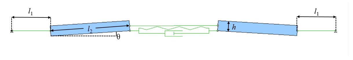
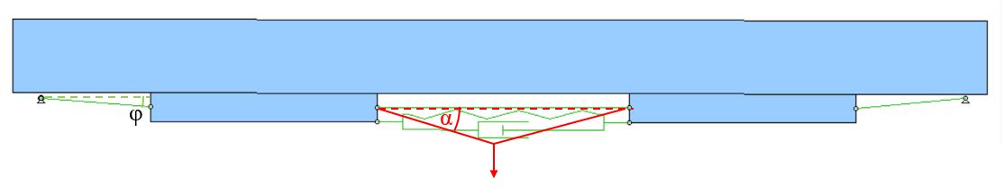
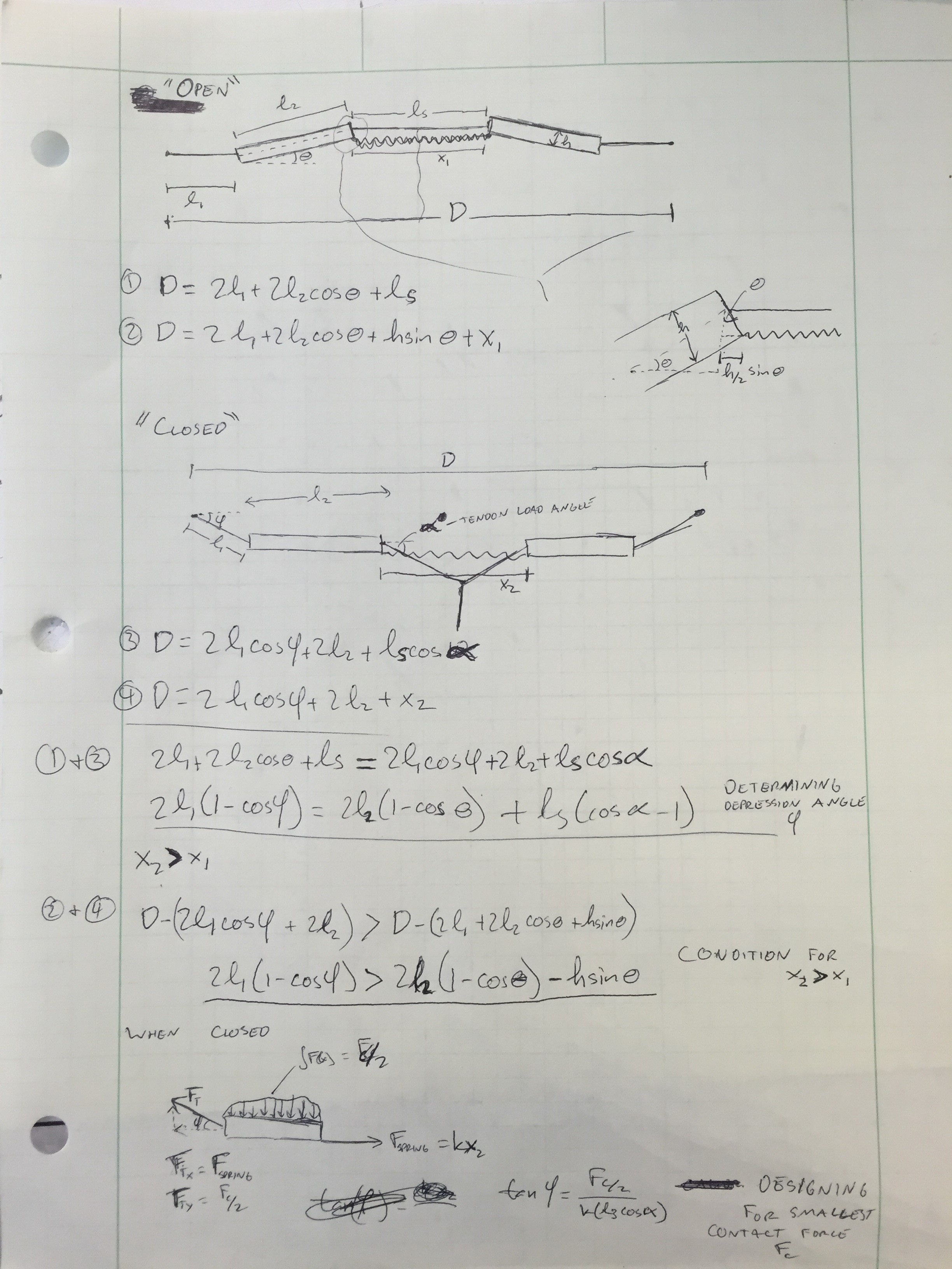
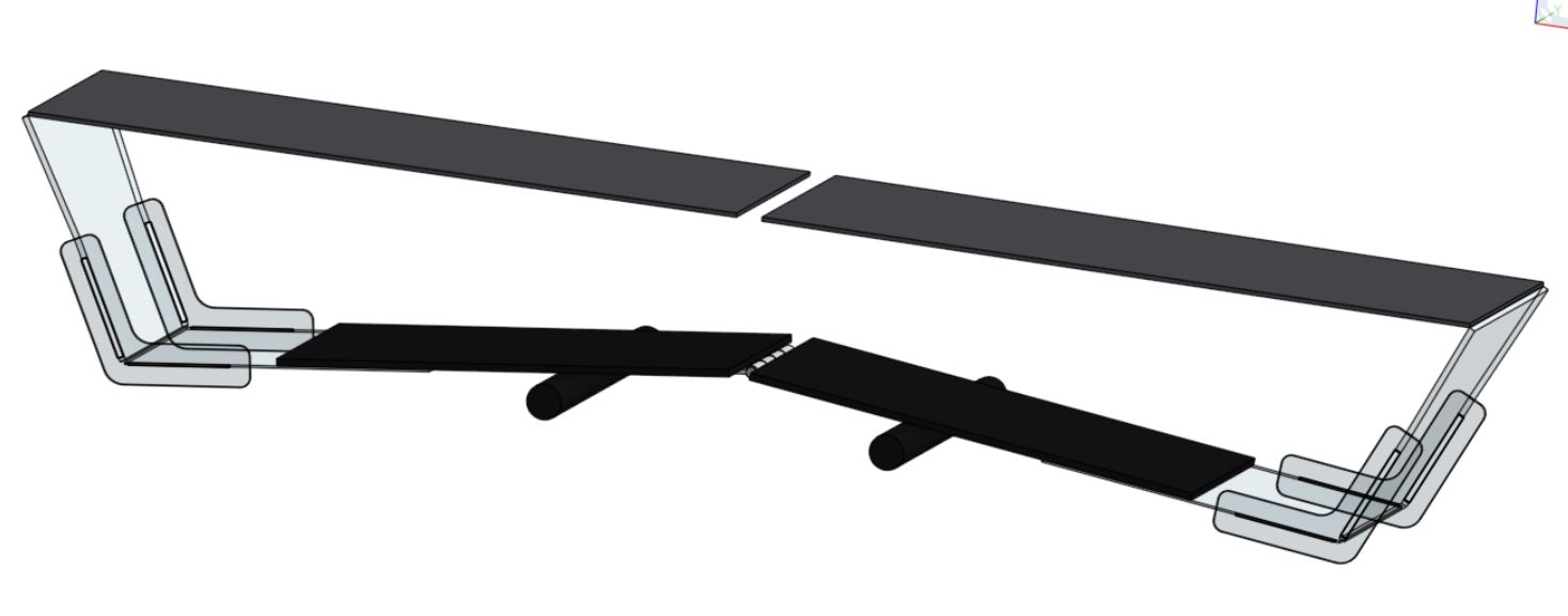
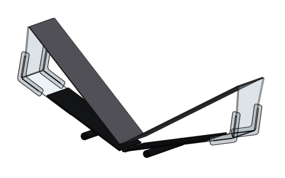
The Matlab program finds paired sets of four variables: Pad angle theta, string length L1, adhesive load angle alpha, and loaded string angle phi (all labeled above). These are calculated from the physical constraints for such a system to function, which are:
1. The 'open ' spring length must be shorter than the 'closed' spring length, and minimized in the gripper's 'open' position
2. The adhesives should be loaded with an angle phi between 7 and 10 degrees.
3. Within the range of desirable adhesive loading angles, the string contact points cannot collide with the surface.
All of these constraints are determined by the pad geometry and spacing, which I'm treating as a constant for the given adhesive pads.
Because these constraints represent three different and interdependent inequalities, I've put all of these quantities in terms of the pad angle theta, which has fairly simple geometric constraints bounding it between 0 and 7.44 degrees (condition 1). I choose to find the maximum allowable loading angle alpha for any geometry set, since these lie more in the adhesive's nominal angle range for normal gripping. However, given my order of constraints, the maximum loading angle alpha for any pad angle theta will result in no depression angle phi (or a very small angle), which requires a very high tension, and thus a very high normal force to be applied.
For work around this, I added a factor to my calculations to take a percentage of the maximum load angle. This allows for a non-zero value of the depression angle phi, which is important for allowing the adhesives to align to the surface and also to reduce tension in the string L1.
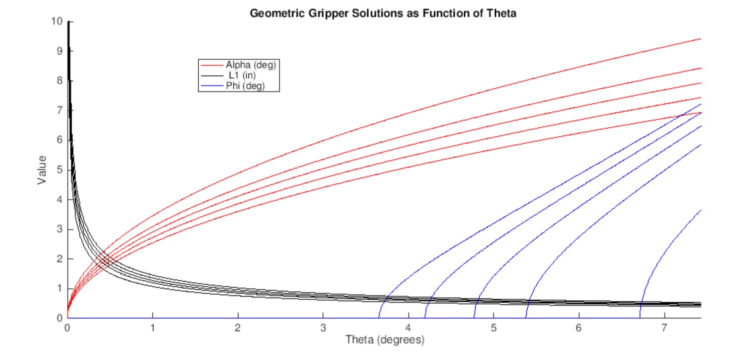
This plot shows a sweep over all theta values, and for load angle reduction factors of 0.7, 0.75.. 0.8. 0.85. and 0.9. All three values move outwards as the reduction factor is increased. For phi, solutions on the X axis indicate that no valid solution exists given the other variables and the geometric constraints. Decreasing the load angle increases the range of possible solutions for phi. The solution I have chose to simulate in the WorkingModel screenshots above has the following values: theta = 7.0, alpha =7.7, L1 =0.485, phi = 5.87.
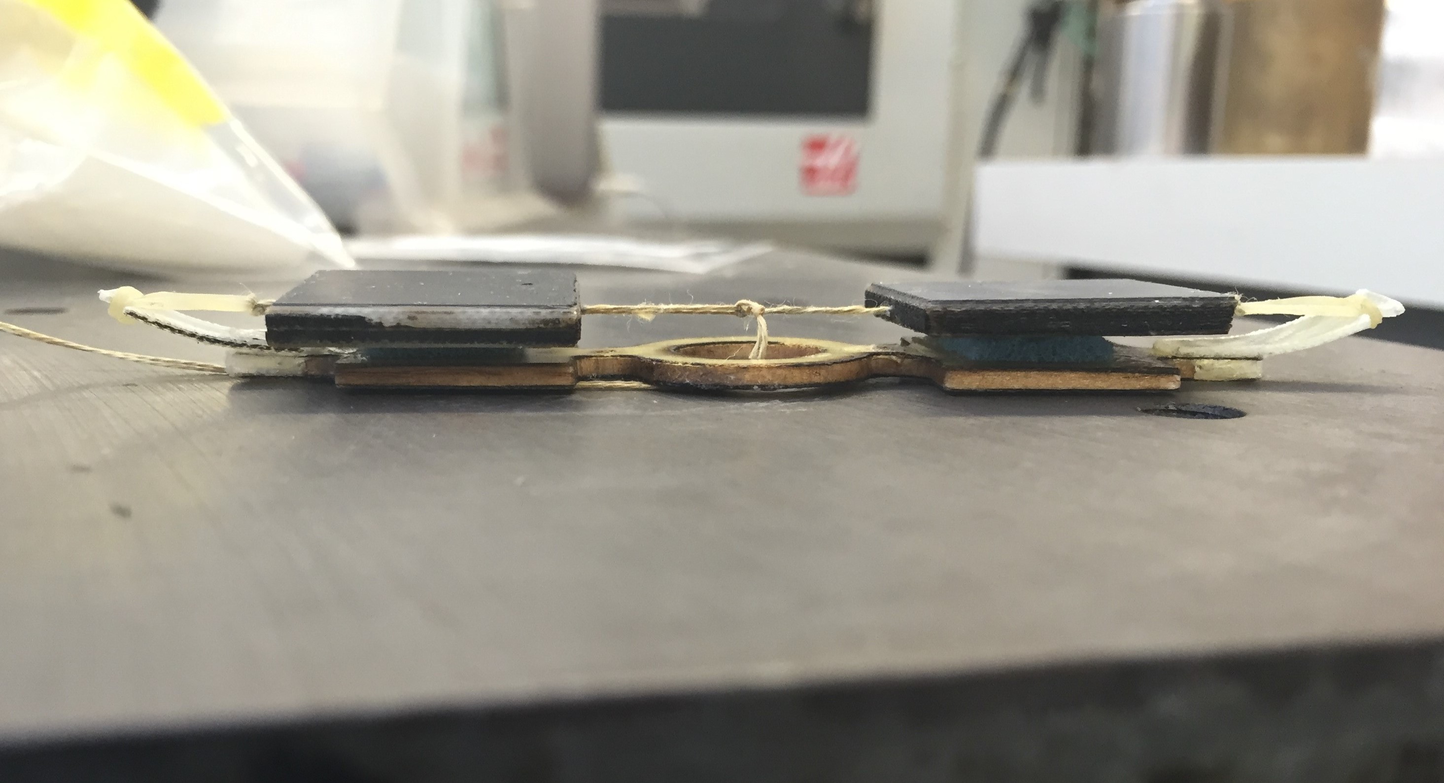
I made a quick prototype using this geometry out of lasercut plywood, kevlar string, superglue, and the gripper pads. After measuring all of my lengths with calipers, I actually managed to get within five thou (!!!!!) of all of my geometric constraints. Unfortunately, the gripper hardly works at all. I'm quietly pleased with the precision of this prototype, but disappointed that a lot of the geometry work I've done hasn't yielded a functional prototype. I'm going to think hard over the weekend about what to do when I come back in on Monday.
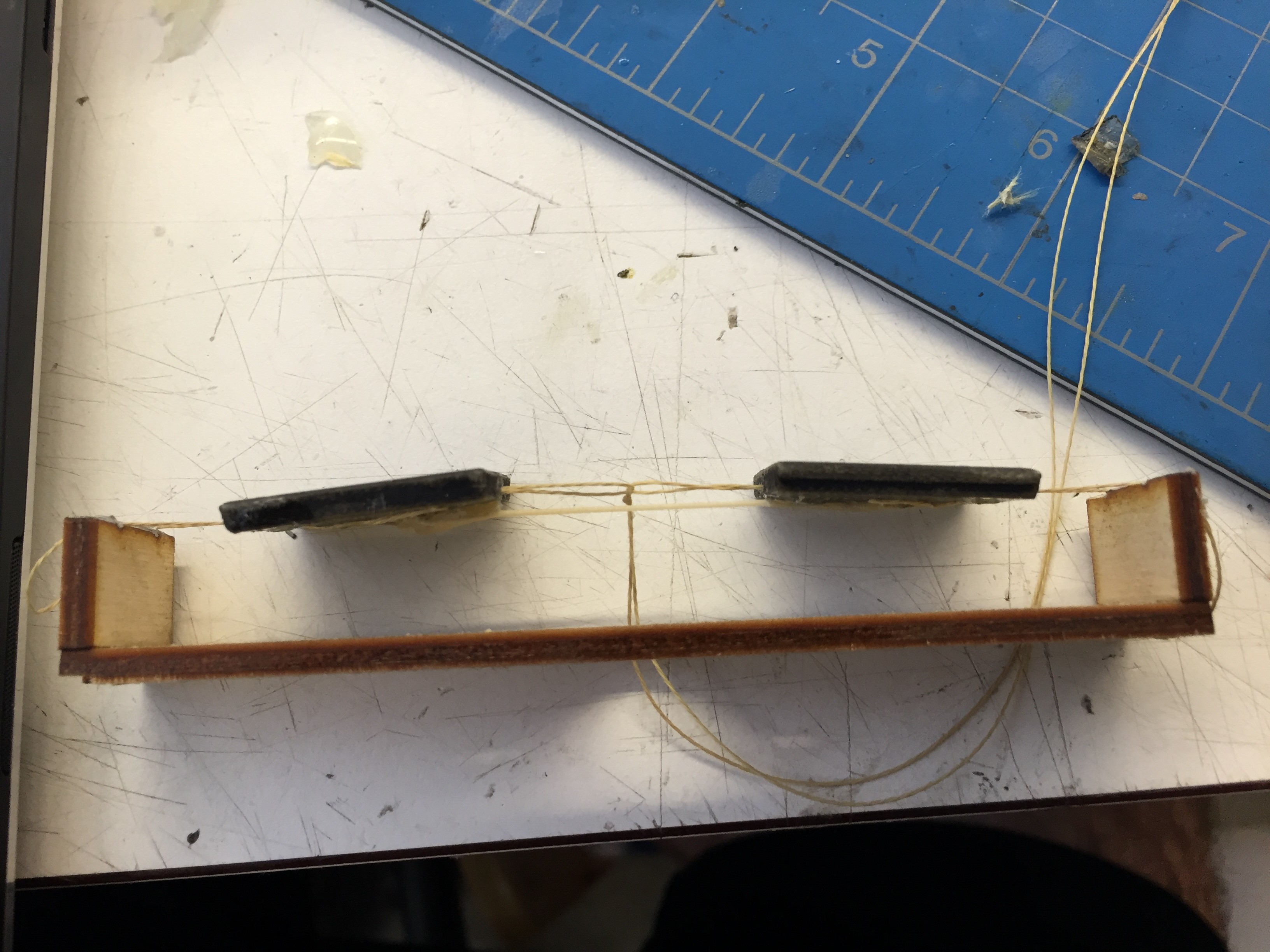
Remarkably accurate yet non-functional prototype.
Thursday, July 21
I did not have a particularly productive morning, since Aaron and I had to return to Western Tool to grab another two endmills. Hopefully this will be the last time we have to drive out there. We finally got most of the way through the stainless steel stock, but broke our extra reach tool on the last pass because we had to remove one of the parallels to avoid cutting it with the tool. For the second time through, Aaron is going to make some disposable aluminum parallels to avoid this. One good thing about being so involved in this project is that I am learning a ton about machining. I plan on coterming and hope to take ME318, so this summer will help when I get around to learning to use the CNC machines myself.
In the afternoon, I finally got my Matlab script up and running to solve for useable gripper geometries. I settled on a set of geometries and then modeled the gripper in WorkingModel to confirm these geometries would work. Shortly thereafter, my laptop died and halted my progress for the day. I'm planning on a lengthy blog post tomorrow describing the whole project in greater detail
Wednesday, July 20
I had a much better day prototyping my new gripper design, and I did some further analysis to try and identify a specific geometry that will meet my design requirements. Because the gripper works almost entirely due to the subtle geometry of small angles, I will need a high level of precision for further prototyping. My afternoon analysis found that the gripper has a maximum resting angle of 7.44 degrees for the adhesives, and a maximum load tendon angle of 10.5 degrees. I was also able to confirm that a solution fitting all of my geometric constraints exists, and I will begin making a more precise prototype tomorrow.
I was also excited to present my work to Matt, Capella, and Will at perching meeting. They all found the design interesting, and has some good suggestions. Matt also confirmed that a gripper with a tiny contact force would be useful in free-flying applications, so I will continue working on this. I also rebuilt my somewhat functional prototype, to demonstrate the light contact force required. This prototype underscored the need for higher precision, so I will trade in the Loctite and superglue for OnShape and the TLTL laser.
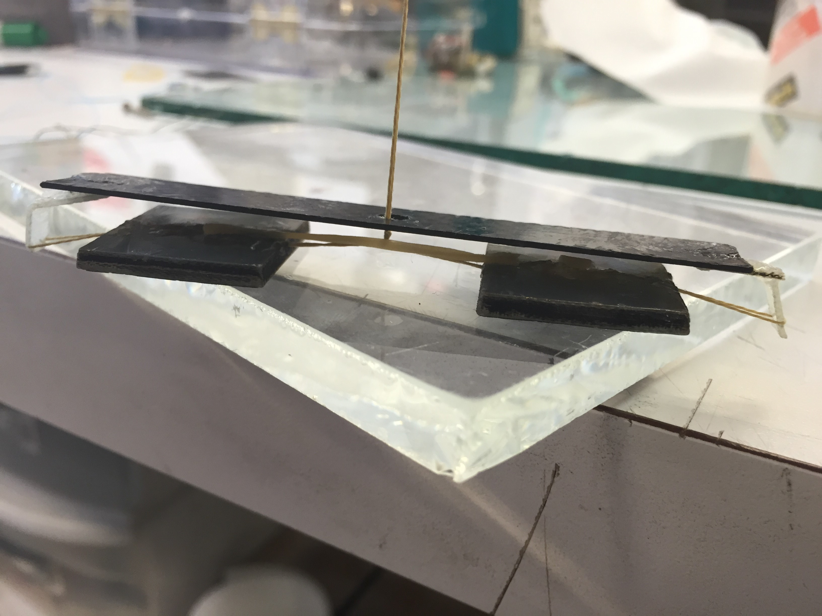
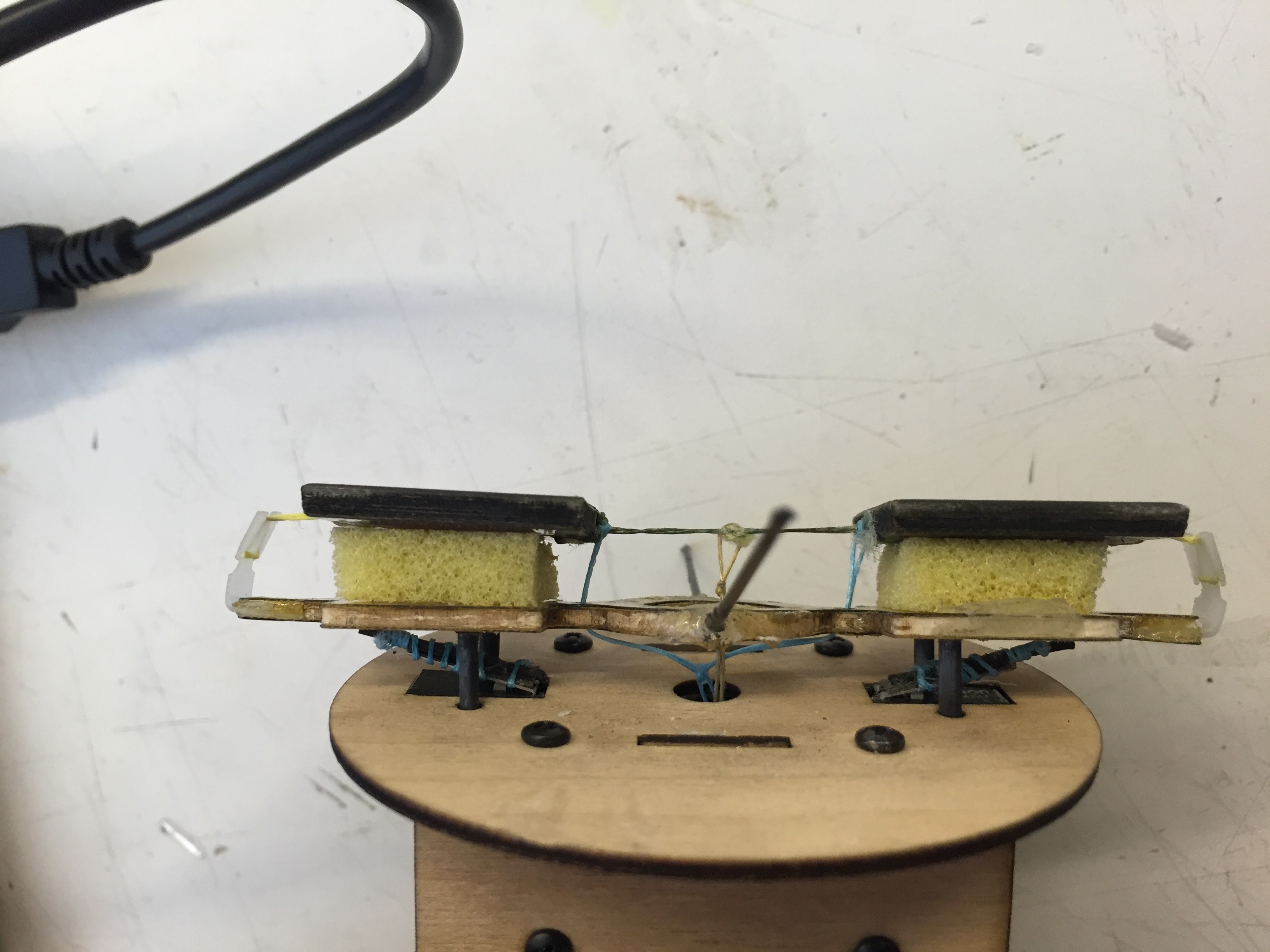
Rebuilt prototype. Note that the fiberglass wings on the ends extend 'through' the plane of the adhesives when loaded. Other than removing a significant amount of slack from the mechanism, this is the only remaining hurdle, and I hope to solve it with some clever geometry and algebra.
Lastly, I spent some time attempting to write a Matlab script that would solve for all possible geometric solution. The constraints are a stacking sequence of inequalities, with the range of possible angles or lengths dependent on the previously calculated ranges. My script got pretty complex quickly, but hopefully I will have something useful from it tomorrow to inform my CAD design process.
Tuesday, July 19
I talked with Will this morning about my new gripper idea, and spent most of the day prototyping. My first prototype was promising, although the string anchors on the ends extended too far, so it only successfully grabbed things that were smaller than its overall width. To fix this, I added some 1/8" plywood backing to the adhesive pads so they would clear the end. This prototype has not been working at all. I removed the elastic in the middle and cleaned the pads and the glass, but it still hasn't been working.
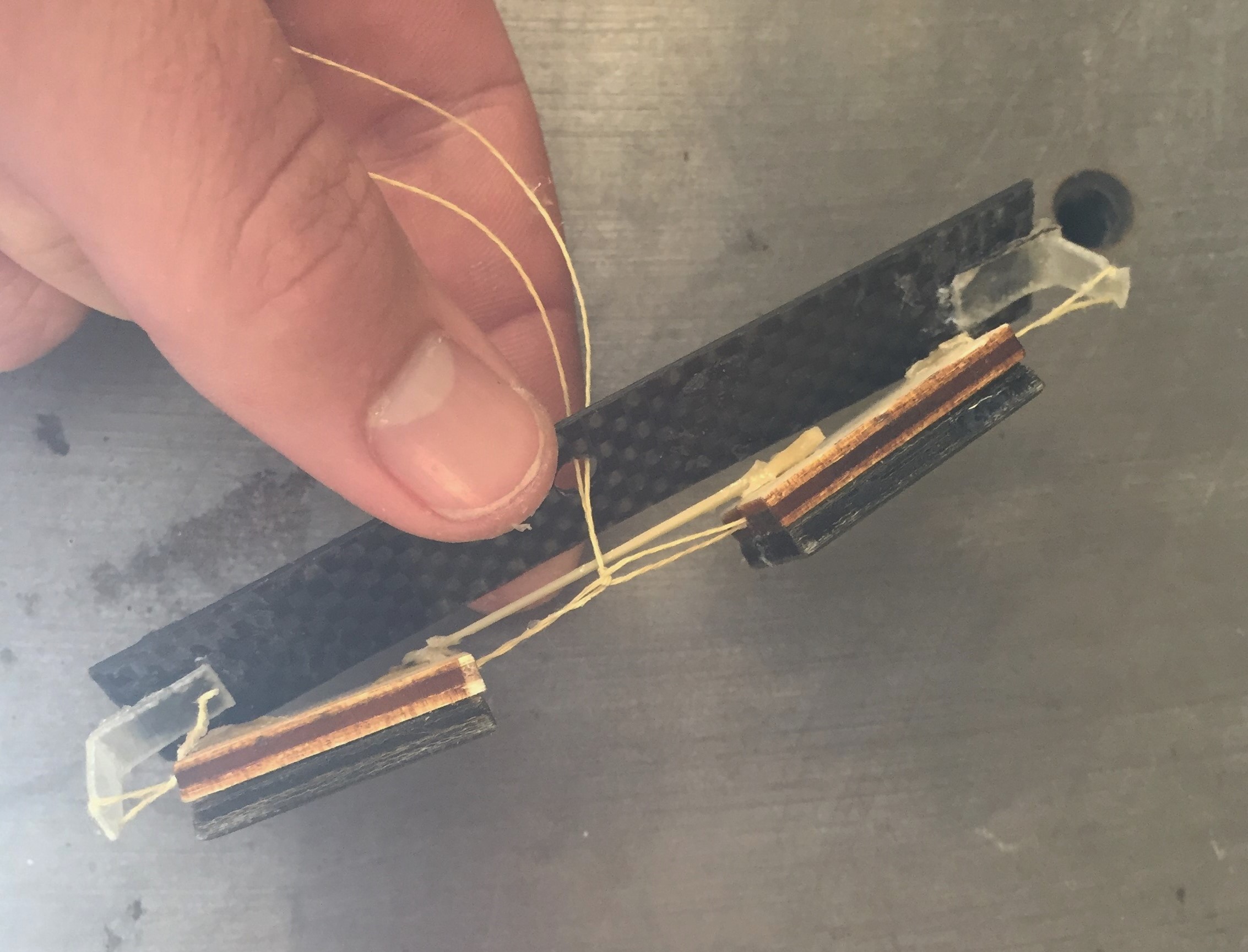
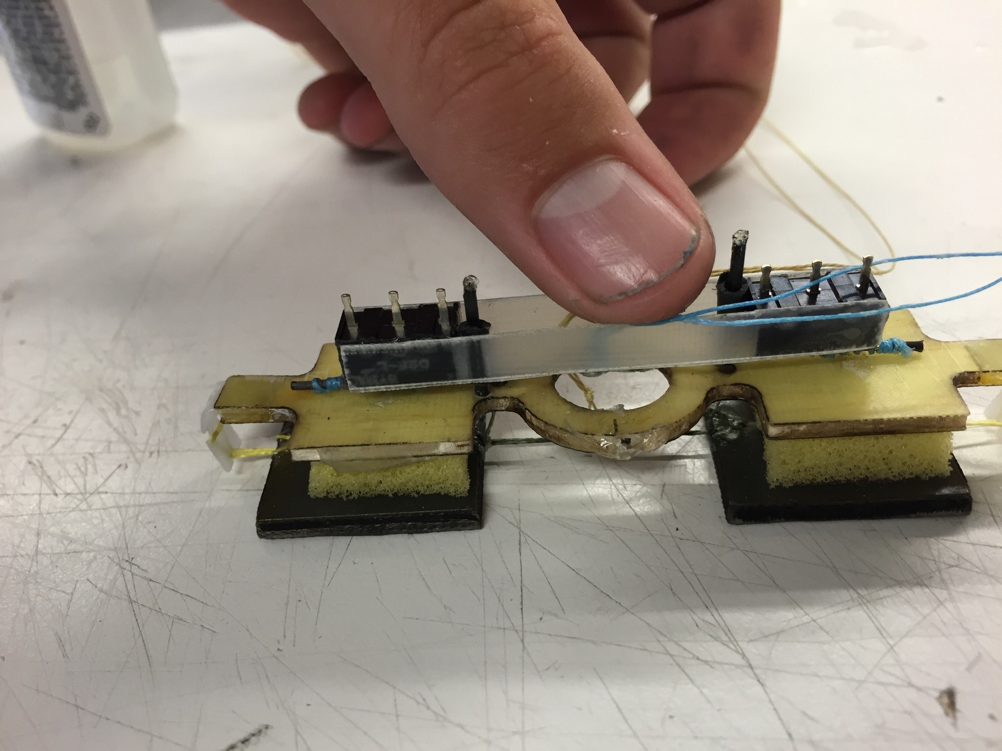
Prototype from this afternoon, which hasn't been working.
I'm nearly certain that remounting the load tendon on the wood backing plate is the cause of this, since it needs to be closer to the adhesive contact plane to load the adhesives in shear. I'll update this tomorrow, and hopefully it will help.
Monday, July 18
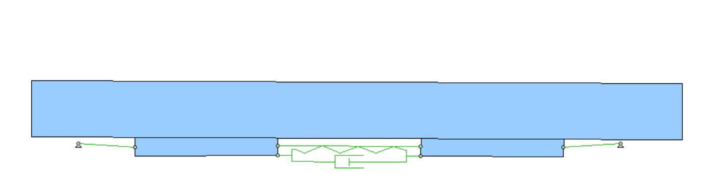
After a restful and productive weekend, I had a great day back. I thought a lot over the weekend about my idea for a passive, light-contact gripper and even did some FBD analysis at home on Saturday. My idea involves modifying the standard opposed grip adhesive design by adding a small spring or elastic element behind the two pads. The elastic elements on the edges are removed and replaced with inextensible string.
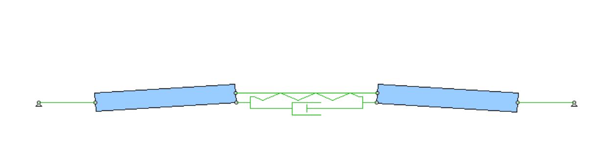
The spring causes the adhesive pads to be titled at a slight angle in their 'open' state, and adding a normal load will makes them come flush to the surface. The adhesives should be loaded in shear and 'stick' to the surface before the load tendon is tensioned. Once that tendon is loaded, the gripper behaves similar to any other opposed gripper. The key to this is the relatively small angles and single spring. The small angles mean that moving from the 'open' to 'closed' positions should require very little force, while the spring will tension the adhesives inward once full contact is made. It is essentially a bistable mechanism where the adhesives create the second "stable" position.
I created a quick Working Model 2D simulation to get a feel of how it would behave, then did some geometrical analysis on paper to figure out some of the constraints. I found geometric constraints for some of the important conditions, as well as how to calculate the contact force.
I think I will start pursuing prototypes of this tomorrow after talking to some other people in the lab about it. I'm feeling pretty good after seeing the Working Model sim behave the way it should.
Aside from that project, this morning I cloned the gripper I made on Friday, and it performs just as well. I might use the two of them to explore simple load sharing on version 2 of the Astrobee gripper. Aaron and I also drove to Western Tool in San Jose during lunch to get new carbide endmills. We stopped at Tacos el Gruellense on the way (yum), and he started machining our burger brand in the afternoon. He was pretty nervous about machining the 304 stainless, but the tools had no problem getting through the material and the only real issue was that the 1/4" endmill was a bit noisy. He'll probably post a picture of our progress so far on his blog.
Week 4
Friday, July 15
I felt a lot better today. I had a pretty tough time this morning because we ran out of coffee at the house, but I ordered a strong Starbucks drink after lab meeting that took care of that. After lab meeting, we found out how not to do MERL BBQ. Food was slow getting served, and the group running it decided to cook chicken legs and wings, which take forever. A ton of MERL people ended up just getting food at Tresidder, including myself. Aaron, Bessie and I have been discussing whether we want to cook chicken breast for our BBQ in two weeks, and I think we all want to prove it can be done and done well with proper planning.
Updated gripper, requiring lower contact force
When we returned from lunch, I made two small breakthroughs in gripper performance. I was able to build a gripper assembly similar to the ones we had been using, but with a much lighter contact force required. I also had an idea for a completely passive, self-locking opposed gripper that would function similar to the collapsing truss mechanism, but for a much lighter contact force range. I did a lot of quick and dirty analysis of the geometry and some FBD's on the white board, and I would like to write it up more legibly and then get feedback from Matt and Hao. I might even write it up tomorrow so I can talk to Matt early on Monday. I felt a lot better about my progress today overall, and will have something to look forward to attacking early next week.
Thursday, July 14
I got in a bit of a rut today. Since finishing the first version of the gripper on Monday, I've been playing around with the adhesive pad assemblies trying to squeeze some extra performance out of them. I read a whole chapter of Elliott's thesis today on design and performance of opposed grippers, and skimmed through some other related BDML papers from the last few years. I concluding that the gripper assemblies I had been using were as close to optimal as they could be given their age, so I turned my attention elsewhere. Using the post-treated adhesives is always an option if necessary, but not much more can be done to increase the normal load on the mechanical side. I did email Hao asking for tips on reducing my minimum required contact force.
I decided that increasing the normal load held by the gripper would require using multiple pad-pairs, so I will need to devise some sort of load-sharing mechanism to add adhesive pad pairs efficiently. My afternoon was mostly spent doing load-sharing research, and I read the relevant sections of Hao's space gripper paper about four times, then discussed the matter with Arul to clarify some things. I've been a little frustrated the past few days, since I feel like I haven't made much progress and have been spinning my wheels. Tomorrow morning I 'm going to write a document for UPenn about how to use/maintain the curved surface gripper I sent them, so that should give me some momentum going into the weekend. At the very least, I went through a lot of recent papers today and learned a ton about some of the things that happened last summer.
I think if I continue to get bogged down next week, I'll talk to Prof. Lanzetta and/or Will about larger quadrotors and what they envision from that potential project.
Wednesday, July 13
There was a really neat seminar this morning upstairs in MERL by Dr. Rebecca Kramer of Purdue. She spent about an hour introducing some of her lab's work in the field of soft robotics, particularly in using a liqui Gallium-Indium mixture to create stretchable, flexible strain sensors. She also talked a bit about using SMA and heated thermoplastics to create 'soft' actuators. She had some really cool manufacturing techniques that involved inkjet printing a layer of liquid metal spheres, then breaking the hard oxide shell of spheres in the desired conductive pattern to make very intricate geometries.
After the meeting, Aaron and I went to Alan Steel to get stock for our burger brand. After doing research, we settled on 304 stainless, which is food safe and will last longer than carbon steel, although it will be more difficult to machine. I observed him and Arul discussing the feeds and speeds for the individual machining operations, and I picked up a good deal of machining theory, which I find fascinating. Hopefully I will get to take ME318 someday.
I spent the afternoon playing around with some new gripper designs in an attempt to reduce the contact force required to engage the adhesives. I was somewhat successful, and managed to create a gripper assembly that would grip under its own weight, but only under ideal conditions and immediately after cleaning. The gripper did max out around 6N of normal load so I will probably continue to iterate on the design.
Tuesday, July 12
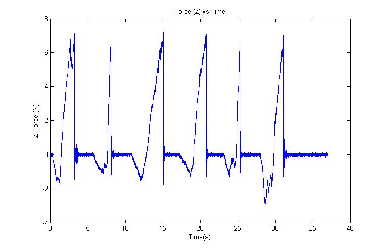
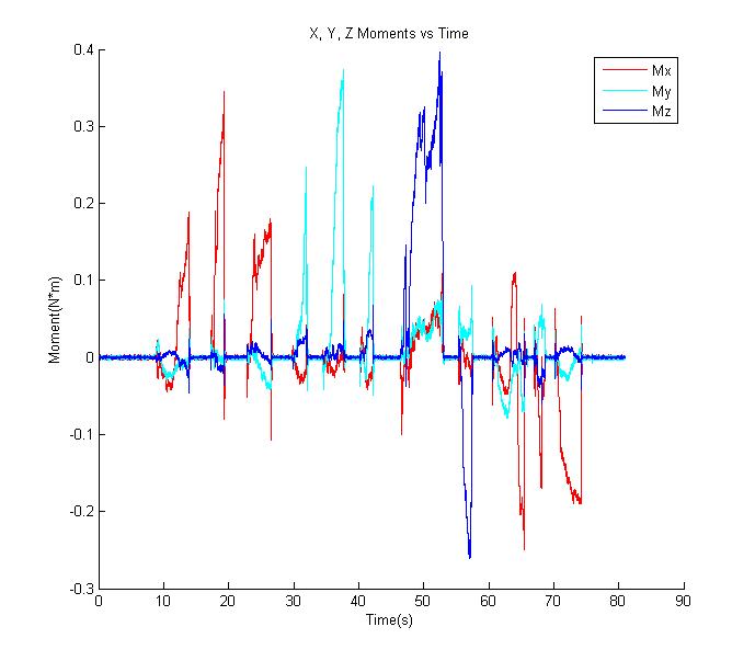
This morning I took some preliminary ATI data for the actuated flat surface gripper. I found that it consistently supported a normal load of just over 6N, and a moment of 0.2N*m in each direction.
After lunch, I thought at length about how to improve the gripper performance. I ended up reading through Hao's space gripper paper. He wrote that he each adhesive unit was able to withstand 13N normal, and only required a a 0.1N contact force (as opposed to 0.4 N for mine). I discussed the performance of opposed grippers with Arul for awhile, and realized that to get more performance out of the gripper, I needed to a better actual gripper pad assembly. Some quick tests revealed that the demo gripper used for lab tours-which has very worn adhesive pads-performed better than the gripper pad assembly I was using. I will start by rebuilding the gripper pad assembly from the ground up to remove that performance bottleneck, and then will modify the wrist and actuators.
Monday, July 11
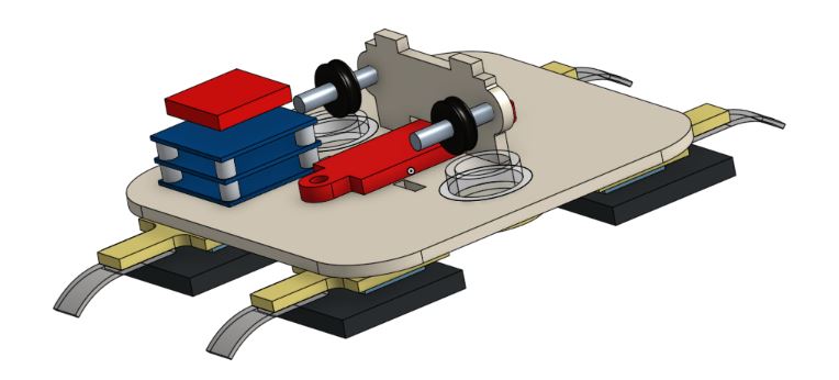
I was pretty pleased with my progress today. I finished the initial powered version of the gripper. Writing the control code for automatically engaging the adhesives took seven lines, and with clean pads it works flawlessly. My next task will be to do some more rigorous pull-off tests using the ATI force/torque sensor to quantify its performance. Matt took a cool video of the gripper in use, and I made this simple diagram showing how the tendon mechanisms work.
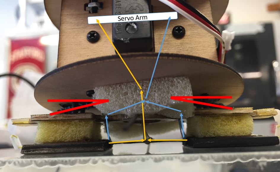
In the image above: turning the servo arm clockwise engages the yellow load tendon to load the adhesives. Turning counterclockwise engages the release tendon, which peels the adhesive patches away from the surface. Limit switch positions are shown in red, and these require both pads to be loaded for the servo to actuate.
Week 3
Friday, July 8
I soldered together the electrical components for the Astrobee gripper. I first assembled the three layers of Tinyduino boards, with the protoshield on top, giving access to various pins. I prepped a small stripboard, and soldered male header pins to this first. From here, connected from the header pins on the stripboard to their appropriate pins on the Tinyduino protoboard. The header pins will allow for easy connection with crimp connectors from the servo and the limit switches. Lastly, I had to solder the crimp connector wires to the limit switches.
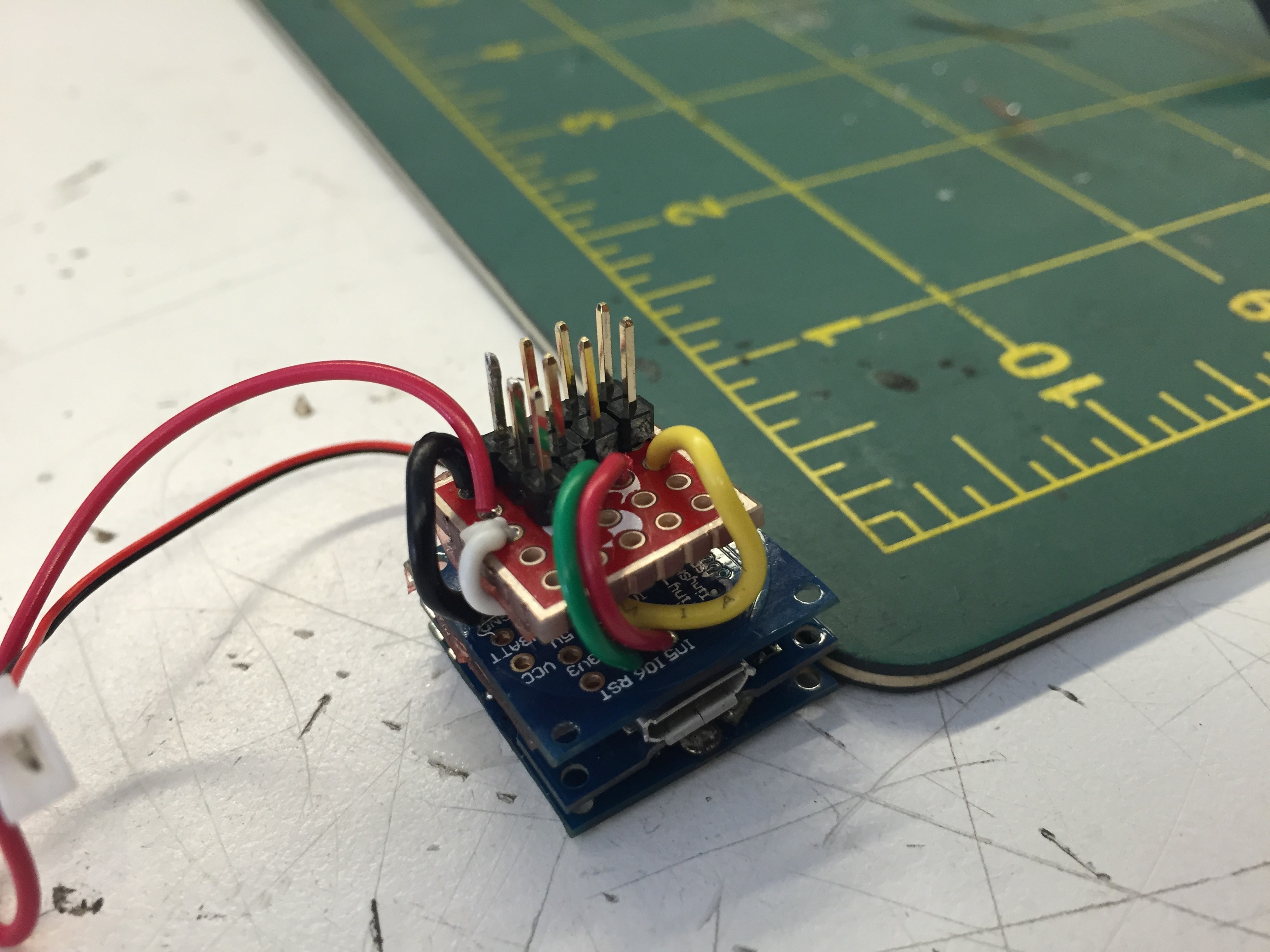

Finished Tinyduino stack and pin usage table.
In the afternoon, I ran a final check on the UPenn gripper before shipping it off. It should arrive late next week, so I will draft an email to Justin detailing its use and maintenance in the coming days.
We also had the first MERL BBQ today, hosted by the DDL. They made pretty solid hamburgers, and the new location on Gibbons grove is an improvement over last year, and the charcoal grills are an upgrade over the old propane grills from the PRL courtyard. At the BBQ, Aaron, Arul and I discussed a project Ian had proposed last year: a BDML burger brand for our MERL BBQ. We plan to machine the BDML logo out of steel, heat it to a very high temperature, and sear the logo into the burgers. As the only carnivore and most likely grillmaster of the three, I will working closely with Arul and Aaron, who bring machining experience to the table.
Thursday, July 7
I spent most of the day finish assembling the Astrobee gripper. Preliminary tests using the manual servo driver were very promising, so I turned my focus to integrating a Tinyduino and making making the gripper automatically actuate. In the afternoon I did a lot of preliminary research into how to use Tinyduino for servo control, as well as how to wire limit switches to the I/O pins. For how long I've known that I wanted to go into mechatronics, I'm a bit embarrassed to admit I've never gotten around to learning how to use an Arduino, so this will be good practice. I was able to upload and run one of the simple sample programs, and will be beginning to test and wire the limit switches and motor tomorrow.
The gripper remounted on the plywood frame. The yellow load tendon will be tensioned by a small servo automatically when both limit switches are depressed. The blue release tendon releases the adhesives by turning the servo in the opposite direction.
I also ran some final load tests and made some last minute tweaks to the UPenn curved surface gripper. I was able to suspend three kilograms from the bottom of the gripper while attached to my nalgene, so I am thoroughly convinced the gripper will have no problem with the 500g quadrotor at UPenn. I ship it to them tomorrow.
Wednesday, July 6
I had a video call with Justin and Andrew from UPenn as well as Hao calling in from China. We discussed the curved surface gripper I had built, and agreed that I will be making a few minor modifications to it tomorrow, then shipping on Friday. I spent the afternoon designing and assembling the first wooden prototype of the Astrobee gripper, using a lasercut plywood construction that matches Matt's Astrobee mock up. I began integrating the motor, limit switches, and adhesive pads before having to call it a day.
Tuesday, July 5
After a fun but tiring Fourth of July, I came in this morning and finished the UPenn gripper. It took a while to go through the CAD of their attachment point and design something that would interface with what I had built. Eventually, I laser cut some acrylic pieces and attached them to the carbon structure using 3/4" standoffs and some 4-40 screws. The whole assembly is quite tall, but this shouldn't be of much consequence since the grippers itself is very light, and the UPenn researchers are very skilled in quadrotor control. I will be discussing with Justin tomorrow (as well as Hao calling in from China) over video chat in the morning.
Gripper with acrylic mounting plate.
After finishing up the gripper around four, I shifted back to the Astrobee gripper. I mounted the limit sqitches I had tested on Friday using some rudimentary linear slides made from carbon tube and rod. The whole assembly feels remarkably sturdy, and my initial pull-off tests after depressing the limit switches by hand were very promising, with no adhesive failures occurring if both switches were depressed when I first pulled the load tendon.

Limit switch mechanism in open and closed states.
Week 2
Friday, July 1
No blog post from yesterday since the BDML web server was down, but I made a lot of progress on my gripper CAD yesterday. I spent a lot of time familiarizing myself with OnShape's mating system as I attempted to get the gripper to behave as close to real life as possible (without flexible parts). I used limits on the rotational mates sand gearing relations to give the gripper a fairly realistic range of motion. I'll probably revisit this and complete it at some point since it will make a nice graphic for my poster at the end of the summer.
OnShape CAD Models of the top half of the gripper mechanism.
I got a new project from Matt yesterday afternoon, which is a flat surface opposed-gripper for an upcoming NASA project called the Astrobee that will be sent to the ISS. I will have to make a gripper that can function in zero gravity, where objects will float away if too much force is applied. I spent most of today (Friday) performing pull tests on the adhesive to find the minimum force necessary to create adhesion with one of the prexisting gripper pads. With clean pads, I was able to consistently create adhesion with about 45 grams of force (0.45 N). I will begin designing an active mechanism to tension and engage the adhesives after a limit switch is engaged.
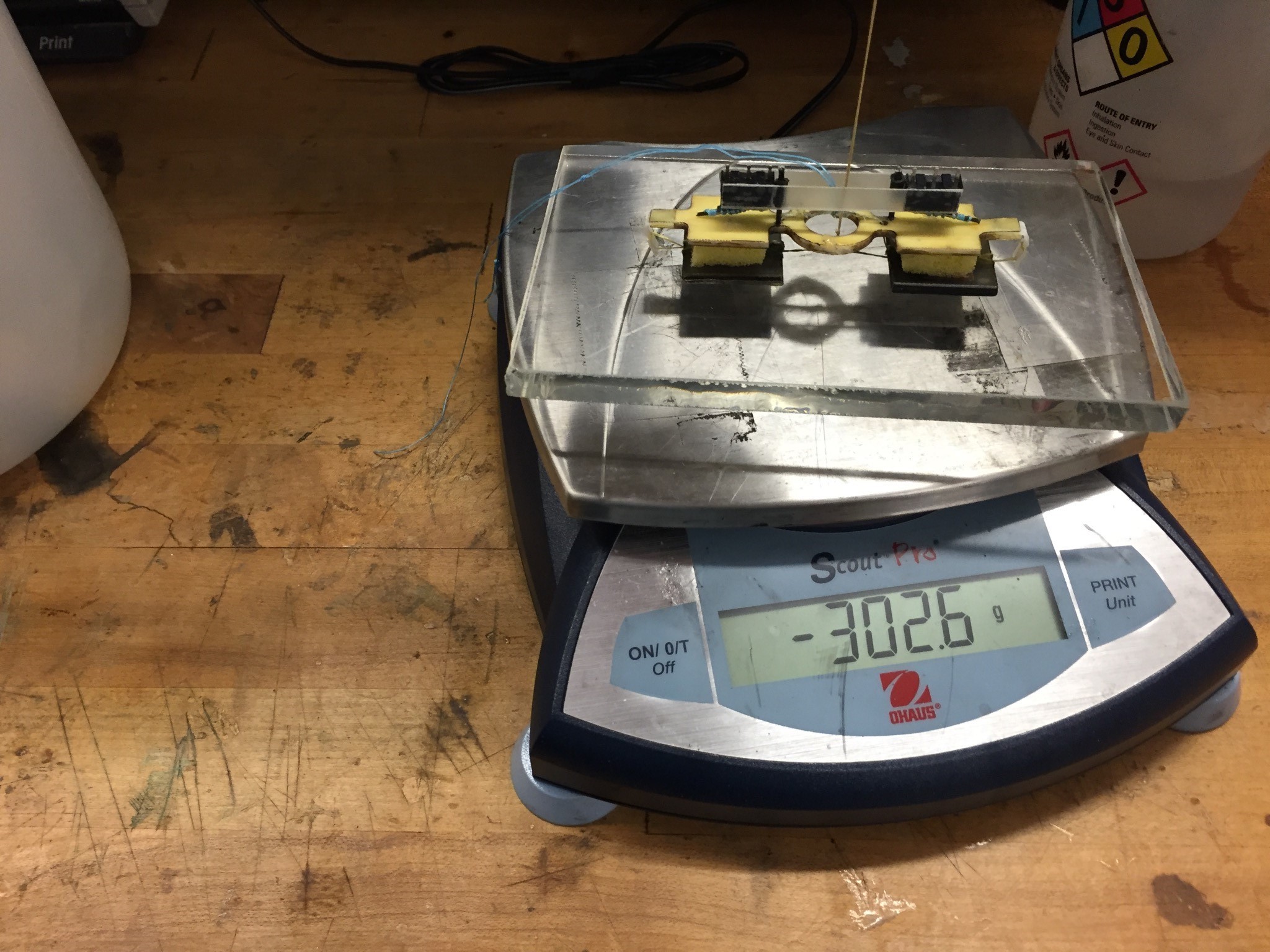
Successful pull-off test. Scale reads negative since I am lifting the glass plate.
Wednesday, June 29
I put the finishing touches on the UPenn gripper today. I played around with the foam, and added rubber bands to stabilize the gripper and prevent it from rotating from its home position. Once I get the attachment point CAD from the UPenn team I should be able to quickly finish and send it off to them. Morgan was also back this morning to finish up a few administrative things for the T-RO paper and his thesis, it was good to see him.
Final gripper mechanism. The added rubber bands prevent the gripper rotating relative to the base plate, and act as a mild rebound spring.
In the afternoon, I started to CAD the gripper mechanism on OnShape, a relatively new cloud-based CAD program that Arul really likes. This will be a good chance for me to brush up on my CAD skills, and will give me an excuse to learn OnShape. I found it fairly intuitive given my solidworks background, but I had to go help clean the TLTL before I was able to make much progress.
Tuesday, June 28
Latest prototype hanging from a Nalgene water bottle.
Today was a very productive day. I finished my first fully functional gripper, and all that remains is fine tuning over the next few days. The new mechanism for actuating the release tendons worked extremely well. One unanticipated effect is that the long carbon rod flexes a small amount near the edge of its travel, which should alleviate strain on the servo.
Release tendons tensioned by hand, with visible flexing of the carbon rod.
I spent a lot of time trying to find the right foam stiffness and geometry to both fire and reset the gripper; I settled on some soft yellow damping foam that worked particularly well. I tested the release tendons using Matt's manual servo test controller, which I had used last summer. I got very consistent triggers and releases with the final foam pieces, and with freshly cleaned adhesives I was able to grip a water bottle so firmly that I could not pull it apart with my bare hands without breaking the large carbon fiber components. Tomorrow I will constrain the free floating gripper from rotating, which will help make the triggers and releases more consistent.
Monday, June 27
Today I went backwards a lot. I realized that with the current design, there was no convenient way of providing enough slack for the release tendons without them posing an entanglement risk. I thought about different mechanisms for providing tension to these, but none seemed particularly feasible. After a ten minute design jam session with Will in the afternoon, I decided removing the rebound spring would alleviate many of my problems. I also judged that from the probable use cases, a rebound spring wasn't essential. About ten minutes after coming to this conclusion, Justin replied to my email from Friday, and his design requirements confirmed that a rebound spring was unnecessary. After another fifteen minute design jam session with Will and Arul, I settled on a final design. A servo would turn a large arm in the plane of the quad copter, and this arm would be attached to the release tendons. I don't have pictures today since I disassembled the prototype in preparation for tomorrow.
Week 1
Friday, June 24
I made a lot more progress on the gripper today, and I actually think I might finish earlier than expected (famous last words of an engineer). I wrote a long email to Justin at UPenn this morning asking for some updated/more detailed specs for the gripper, so when he gets back to me I can tune the gripper. This morning I installed a lighter rebound spring, and replaced the superglued spool with a standoff to reduce friction. I also added a pulley and replaced the old load tendon before lunch.
New rebound spring and load tendon pulley.
After lunch, my steel springs came in from McMaster. I was very pleased with how they looked and performed. I also worked on adding the release tendons as actuated by a servo. One of my remaining tasks will be to tension the release tendons so they don't get tangled in the rotors while loose. I will also have to find some kind of rigging to help keep the top gripper aligned with the baseplate.
Steel springs installed on the gripper. Release tendons atttached with tape and threaded to control servo.
Thursday, June 23
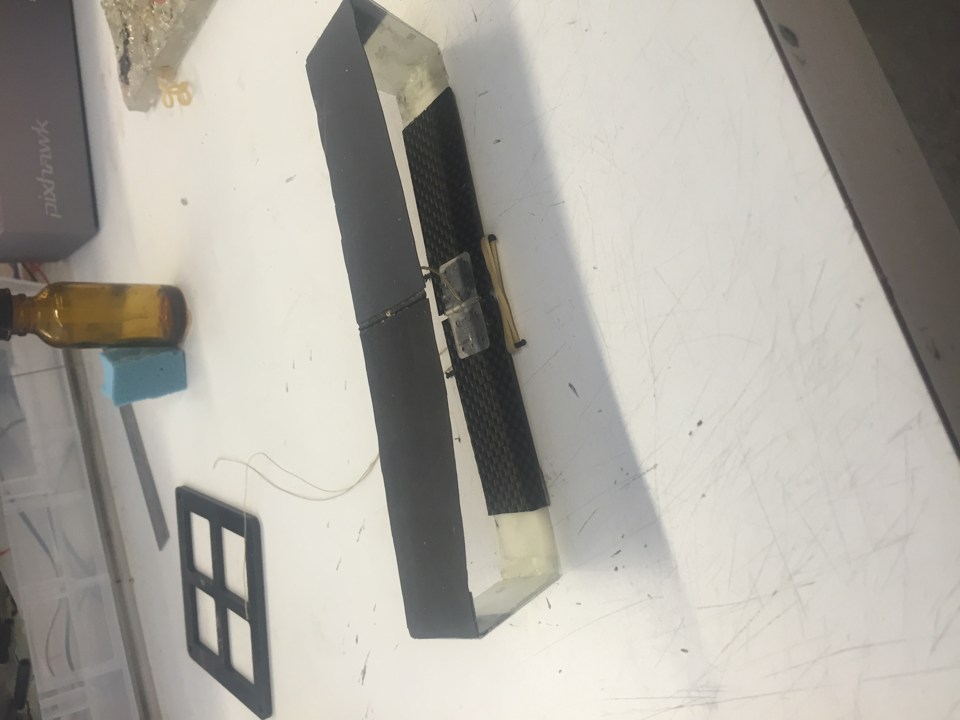
Today, I began building the more robust gripper. I first started by replacing the fiberglass tensioning plates with reinforced, laser-cut pieces including angle gussets. The new plates are far stronger, and allow for a small amount of bending along the bottom piece of fiberglass, which keeps the adhesive film taught.
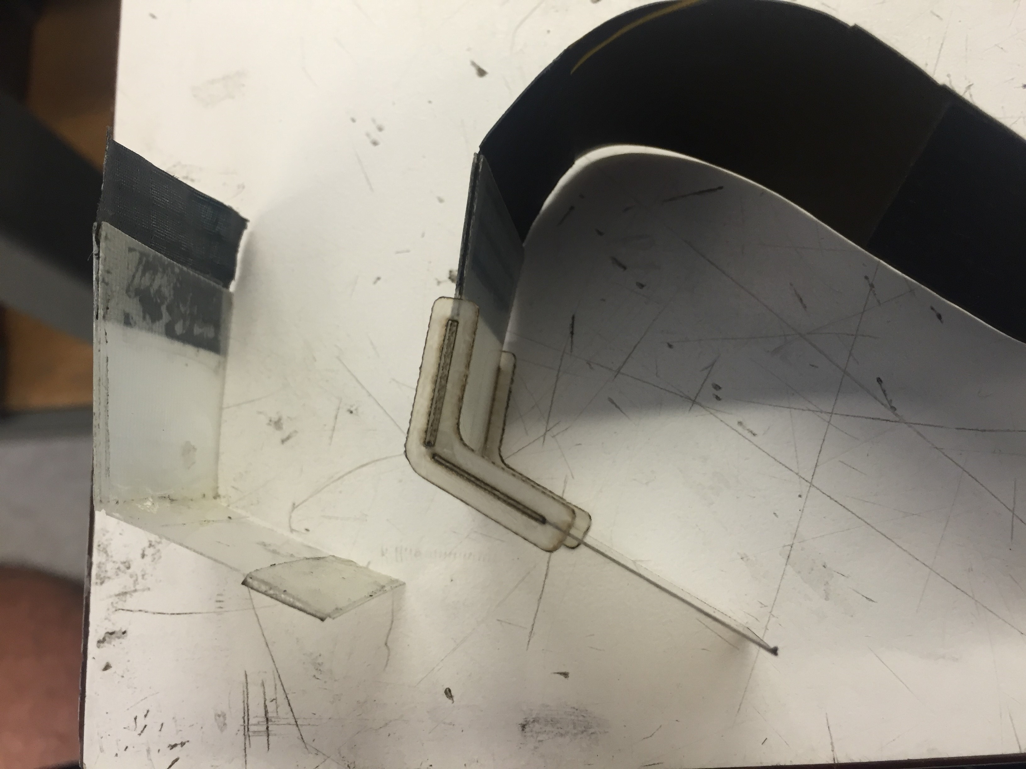
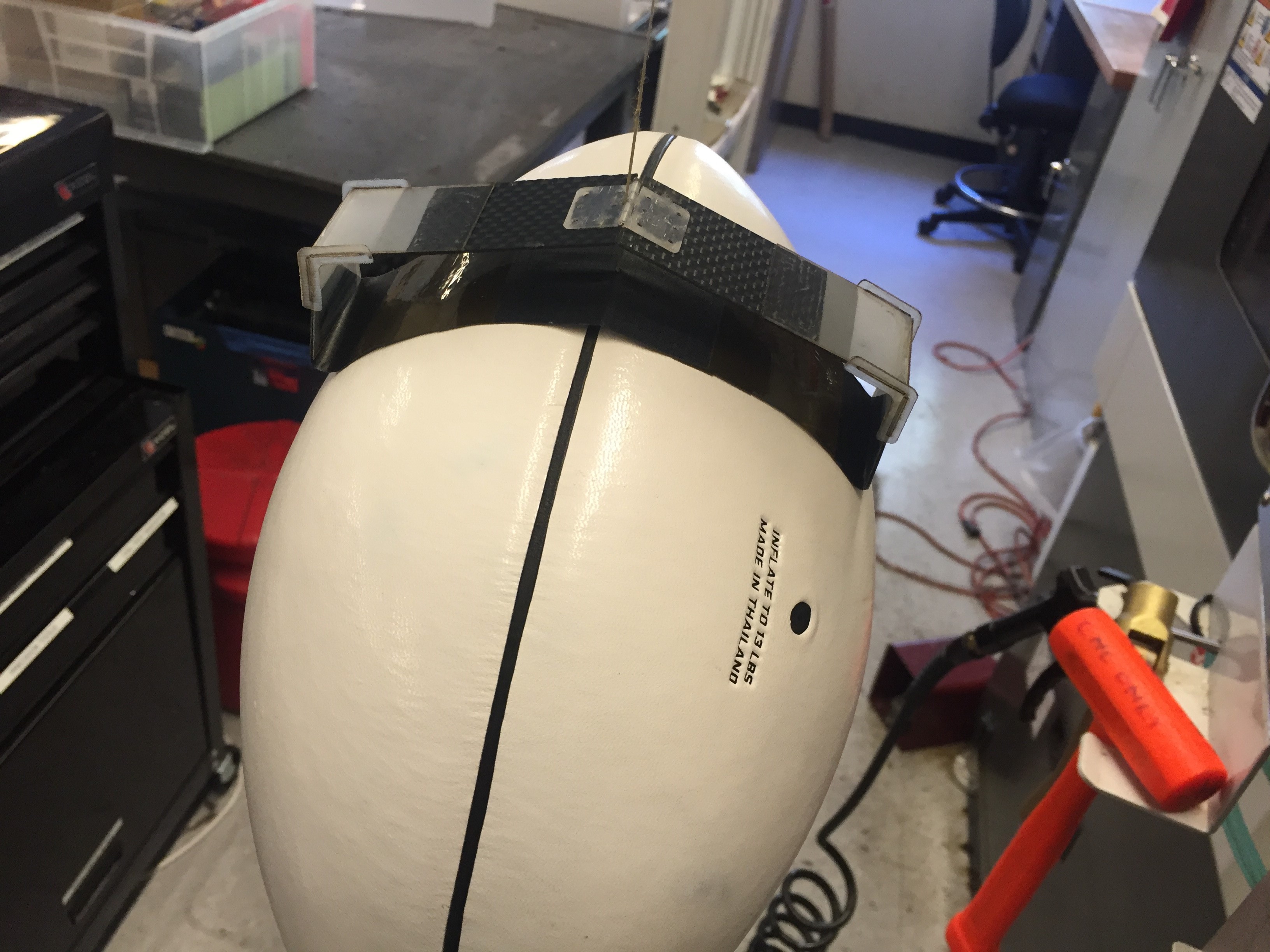
Old tension plate (left) vs new, reinforced plate (right). The gripper easily holds a football.
After lunch, I worked to attach the gripper to the baseplate with a rebound spring. This entailed feeding the load tendon through the gripper and baseplate, and attaching it to a constant force spring I got from Matt. I decided to use at 10N force spring, and modeled the connection off another prototype gripper Matt had built. It took a while for me to figure out how to best mount the constant force spring to the baseplate.
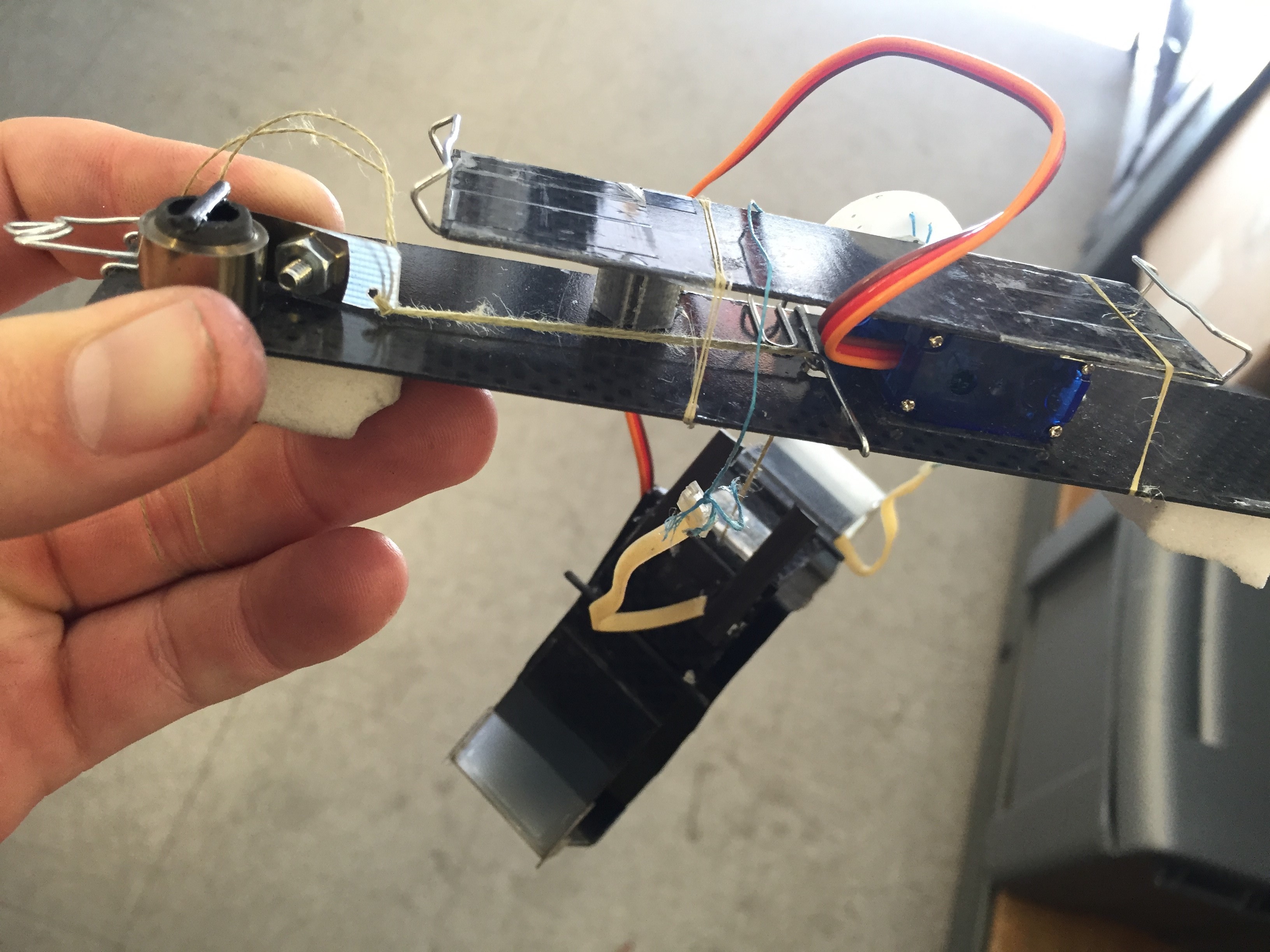
View of the load tendon fed through the baseplate, with constant force rebound spring on the left.
You can see in the image that the kevlar thread is starting to fray, so I will likely replace the thread and add a pulley tomorrow. I also think the 10N spring is too stiff for the ~500g quadrotor, so I'll also downgrade to a spring with about 5N of force, which should allow for a nice gentle extension when loaded. I tried activating the mechanism on some overhead pipes in the MERL hallway with good results.
Wednesday, June 22
At ten this morning, we had a teleconference with Justin Thomas of UPenn. I was involved with some of Morgan's work with him last summer, and am excited to continue working with him. We went over what he wants and specifically how he wants to perch-with a "top mounted" gripper, like SCAMP. We went over basic requirements, such as quadrotor mass and payload capacity, and he agreed to send a CAD file of their quadrotor's attachment point. I continued to work on Morgan's prototype gripper before lunch, and got a mostly-functional prototype of the bi-stable gripper with adhesive film.
Prototype gripper
After lunch, we had perching team meeting. I discussed a lot of my plan for the UPenn gripper with Mark and the rest of the team, and settled on a few improvements from Morgan's previous design: 1. All connections will be reinforced, since our weight budget allows for it and the UPenn team will likely be crashing the quadrotor a few times. 2. Where possible, all elastics will be replaced with small steel extension springs. Steel springs are more sturdy and will not change their spring coefficient with wear. Any rubber bands will be of standard sizes and easily replaceable when they inevitably get fatigued.
Ideally, this will prevent the mechanism breaking while in use at UPenn. In the past, with the flat gecko adhesive gripper, the UPenn team shipped the gripper back and forth to Stanford for repairs. Hopefully, I can build a gripper robust enough to avoid that.
I spent the afternoon planning Thursday morning's work, which should signal the start of making the actual gripper.
Tuesday, June 21
We all arrived this morning for lab clean. I went organized all of the Crazyflie parts and cleaned up the Quadrotor table, as well as helped organize the hardware cabinet. After finishing up and eating pizza for lunch, I talked to Hao and Matt about requirements for the UPenn gripper and how to improve on Morgan's half-assembled prototype. We decided the curved surface gripper had to be sturdy, since in the past the UPenn team has had to ship flat surface grippers back to us for repairs. I then began disassembling Morgan's prototype to get a feel for how it worked, and how to design a more robust version.
Monday, June 20
Today was my first day returning to the lab in nearly nine months. Upon entering, I met some of the new graduate students and caught up with familiar faces. Mark enlisted the SURI's to help move the old Adept robotic arm outside, to make way for a new UR-5. The Adept was extremely heavy and had no hand hold spots, so after removing the control computers, it took us about 45 minutes to move it on to a forklift pallet outside.
The Adept in its new resting place.
After lunch, I talked with Hao about possible projects to work on, and it looks like I'll start by building a curved surface gripper for the UPenn guys to use in their VICOM system. I spent most of my afternoon taking apart a prototype gripper that Morgan had built, and then taking care of administrative things like getting keys and such.
Interlude
After pressing hard the last two weeks before the 9/15 ICRA deadline, Morgan decided to call off submitting, iterate on the robot, collect updated data, and polish the paper. The project that I was working on all summer became known as SCAMP, and the paper was accepted to IEEE Transactions on Robotics, and is now pending publication.
Meanwhile, I followed the lab happenings through the email list, the occasional lab meeting, and a few conversations with Morgan. Upper-level ME classes kept me busy, and around halfway through Mark's class ME112, I decided I wanted to return to the BDML for Summer 2016. In spring, Morgan defended his thesis, so I will be working on a few new and different projects, with some new and some familiar faces.
Summer 2015 Blog
Down below here is my blog from Summer 2015, in reverse chronological order.
Week 10
Friday, August 28
After taking my car in to get serviced at 7am this morning, I Caltrained/skateboarded to lab. At lab meeting, I got to rehearse presenting my poster and answering questions from Mark and some of the grad students. Isabel and I also presented Ian's poster (since he was gone), which was interesting but went fairly well. At the actual poster session, the BDML posters drew a fair amount of attention, and I got to present to and answer questions from four or five different people. It was also cool to see what some of my friends in other labs did with their summers.
In the afternoon, I returned to help Morgan work on the paper. I will try to come in this weekend, but since I have to move out of my housing and drive back to SoCal on Sunday, I'm not sure how available I'll be. I will likely help however I can from home on Monday. Since this wraps up my summer, I'm going to thank everyone in the BDML for their friendship, mentorship, and wisdom. I learned a ton this summer, got to work on a project I really cared about, and experienced a truly fun workplace for the first time.
Thursday, August 27
After dissecting the accelerometer data some more and lining it up with the video, Morgan and I concluded that it was not possible to predict a bad step or a fall from the IMU readings. All of the clearly distinguishable patterns occurred as a result of a good or bad load transfer, and did not appear before the transfer was executed. This means we cannot use these to avoid bad transfer, but if we gently press and slide a foot against the wall, we can detect whether transfer has occured or not (and thus determine whether the pressure normal to the wall was sufficient for climbing).
I also picked up my poster today, and it came out pretty well. I was surprised at how high-resolution my iPhone pictures looked even after being blown up.
Wednesday, August 26
I finished up my poster today and sent it to Fedex to get printed. Morgan and I also discussed adding sensing to the climbing code, using the onboard IMU. After looking through a lot of accelerometer data taken during climbing, I found a characteristic shape in the x and z accelerations that could be used to predict good/bad step or load transfer. This could give us a lot of valuable scientific insight as we push to turn this project into a paper.
Tuesday, August 25
I got in to lab early this morning and finished characterizing the gait from our video last night. I will probably re-do this for the paper (and probably for the poster) since we will be re-tuning the gait today.
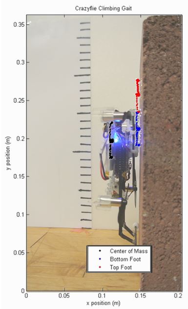
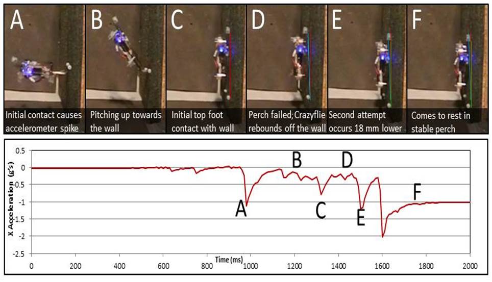
I also made a very cool figure of a successful perch that incorporates accelerometer data. In addition, I took some beautiful photos of Crazyflie for my poster that I'm pretty fond of. I need to finish the poster by tonight in order to get it printed tomorrow.
This afternoon, Morgan fine-tuned the gait and we eventually headed to the clock tower to see how it would perform. Without any on-site re-tuning, it scaled the wall remarkably well, and gave every indication that the clock tower stucco is a much friendlier surface than the bricks we've been climbing in the lab. We also fine-tuned the gait and Morgan added a lot of the code to Crazyflie's firmware, so that it will function mostly autonomously. We got a few videos of climbing with really nice recovery when Crazyflie missed a step. I also worked a lot on my poster, which is really starting to look nice.
Monday, August 24
Today we fought against our signal issue for most of the morning. After ruling out a wiring fault and a communication error, I eventually suggested that we were drawing too much power through Crazyflie's voltage-regulated 3V VCC pin. Morgan and I looked through the Crazyflie circuit documentation and found a protected 3.7V line from the battery that we connected first one and eventually both of our servos to.
I spent the afternoon alternating between helping Morgan tune Crazyflie's gait and working on my poster. After leaving for dinner, I returned to the lab around 9:30 and worked some more on gait tuning with Morgan. We got one solid video of a couple of steps, and I stayed up until 2 using Matlab to analyze the video for a gait characterization. I will probably spend a lot of nights late at the lab this week, so coffee will be a precious resource.
Week 9
Friday, August 21
Morgan made an awesome modification to the firmware last night that allows Crazyflie to detect when climbing has failed and fire all of the rotors in an attempt to re-perch. He also showed me some videos of perching he had done last night. Starting next week I will be staying at the lab late most days. I felt pretty terrible today since I pulled an all nighter finishing up another project last night. I pulled it together and got through the day by drinking an amount of caffeine that can only be described as "medically alarming," but having that project behind me is going to allow me to focus solely on perch/climbing stuff next week. I feel the crunch of ICRA a lot right now, so I need to get it together.
After making some minor mechanical tweaks and playing around with the servo speed limits today, Morgan and I spent most of the day trying to get past the twitching issue in the servos. I had though since I programmed them with a 4.8V supply that Crazyflie's 3V supply was not providing enough voltage for a good power, but after reprogramming them at 3V I confirmed both a) the servos are fully functional at a low speed limit and b) 3V is sufficient to power them at that speed limit. This means that the problem with Crazyflie's control over the servos is either a wiring issue or a communication issue. I looked at the signal sent to both using the oscilloscope, and I'm pretty confident that the wiring is not at fault.
Thursday, August 20
Today was an interesting but highly productive day at the lab. After struggling to get out of bed in the morning, I talked with Morgan and we agreed to go full-court press on Perching/Climbing for ICRA. I then drove to Santa Clara to buy the digital servos. I programmed them before lunch, and then attached some new spine feet that Hao gave me from his stockpile of prototypes.
I also had to solder in programming leads to Crazyflie so that I can reprogram the servos at will. This was one of the cleanest soldering jobs I'ver ever done, and the new motors and feet made Crazyflie look and perform a lot better in initial tests.
Crazyflie with cleaner wiring, new servos, and new feet.
I had some issues with the servos at the end of the day today, so I will be working on them more tomorrow. They seemed to be too jittery, and I suspect it might be the result of some communication errors with Crazyflie.
Wednesday, August 19
I had some major setbacks today. Crazyflie's bottom foot was pretty beat up, so I went about trying to fix it or replace it. With no replacement SDM feet available, I had to jury-rig s flexure out of some foam. It ended up being a general improvement, but getting some real SDM feet soon will be another upgrade.
During our perching meeting at lunch, Morgan and I discussed paper-izing the perch-climbing mechanism, and it looks like he'll be helping me do some experiments and such to make that happen before the approaching deadlines. It's going to be a whole ton of work this next week and a half.
In the afternoon, I played around with servos in an attempt to make the motion less violent. David suggested I perform some servo surgery to convert an analog servo into a digital servo, but it didn't go so well. Tomorrow morning I will be driving to Santa Clara to get the needed servos. The programmable digital servos allow for a max speed, which should dampen and limit the motion to be more gentle.
Tuesday, August 18
I got Crazyflie to climb up a brick pretty reliably this morning. After making some quick modifications that allowed me to charge Crazyflie, I experimented with different gaits all morning. I eventually settled on one very similar to the "ideal parallelogram" I proposed a few weeks ago. Just before lunch, I managed to break Crazyflie's on/off switch, so I will have to repair it or move the current apparatus over to a different Crazyflie (another backup arrived this morning). Jung Hwa also brought the laptop back just before lunch, so I can use that to run climbing and possibly even perching experiments outside.
I spent the afternoon tuning Crazyflie's gait to more reliably climb. I discovered that by feeding the servos invalid duty cycles, I was able to create slower, gentle motion in one direction. This helped with the load transfer, but did not do that much. On the whole, the jerky servo motion is the primary cause of falling off the wall.
Monday, August 17
I had a very productive day of prototyping, and finished with a very mechanically complete prototype.In the morning, it became evident that my previous prototype was both too heavy and suffered from some range of motion issues. I started a rebuild by moving Crazyflie's battery underneath the board.This meant I was able to fit a frame through the space normally occupied by the battery, which brought all of the mechanisms closer to the board. This means that the robot's center of mass is closer to the wall while climbing, which reduces the peeling moment and is advantageous for maintaining a perch.
Left: Battery position underneath the board. Right: Thin profile with battery and servos in the same plane.
The angle of the sliding foot is servo-controlled and driven by a small four bar linkage. The slider is almost identical to many of my earlier prototypes, except that the whole thing can rotate.
Four bar linkage controls arm angle.
Week 8
Friday, August 14
Today we threw MERL BBQ. We got outside early to get the grills set up, and started cooking the first, thick cuts of pork around 11:15. One of the grills was significantly hotter than the other, so it went through the pork really quick to start. When people began lining up for food, I held pork duty and Ian took the warm grill to make burgers. Katie, Isabel, and Nina did most of the other stuff like serving people and making sure that the BBQ was running smoothly, but I was so far in my meat cooking zone that I didn't notice much else.
Once we had to get the meat ready faster, we ran into some struggles. The burgers kept creating grease fires on the hot grill, and the cooler grill took forever to make pork. Ian did everything he could, but a lot of burgers ended up pretty charred. Most of the pork was pretty good even though it took too long. We also overestimated the amount of people who wanted pork, and underestimated the number who wanted burgers. I should have cut the pork thinner to facilitate easier and quicker cooking, but the thick pieces were really juicy and delicious.
Overall, I'd rate the barbecue a success. We knew we weren't going to meet everyone's demands, but we could have switched the ratio of burgers to pork. The burgers probably weren't that well cooked, but Ian did everything he could with some grills that were truly terrible. We came within $10 of our budget, and we didn't even come close to running out of meat for everyone.
Towards the end of the day, I worked a little more on my prototype. I want to get robust climbing done before the summer ends, so I need a big week next week. I will probably try to come in to the lab early a lot next week and put in some really long days. As late August happens, a lot of major deadlines are coming up, so I suspect I won't be alone in that endeavor.
Thursday, August 13
I spent the morning working on new mechanisms that would use two servos to climb. They should look very similar to what I had been building early in the summer, but with the entire linear slide assembly pivoting (controlled by second DOF). Since each servo weighs 4g, the biggest challenge is creating something robust that fits within the 15g weight budget.
In the afternoon, Ian and I drove to San Jose to get food for the MERL BBQ that we have to throw tomorrow. We spent just over our budget of $300 and got 63 lbs of meat (20 of beef, 43 of pork)) for tomorrow. We also got a ton of soda, chips, watermelon, and burger supplies. Isabel join the two of us and we stayed in the lab until 9 cutting and preparing the meat in a marinade. We will probably spend all morning getting set up.
Wednesday, August 12
My attempts at hacking the Crazyflie firmware today went really well. I spent most of the morning reacquainting myself with the firmware architecture and reading through code. We had been using code posted on the Crazyflie Wiki for controlling a piezo-electric buzzer to play music, and in the code there was alternating high and low voltage PWM signals--to create a peak to peak of 6v instead of 3-- so there was essentially an extra pin outputting the inverse of the PWM signal used to drive the first servo. By adding a second parameter to the function call that adjusts the duty cycle, I was able to very cleanly add a second, independent PWM output. I verified the results using a tiny 1g, SMA-actuated servo I borrowed from David. While the SMA servo was really cool (and super light), I ultimately decided to add a second 4g, Hitec HS35, which is the same servo I had already been using. The second degree of freedom will greatly simplify climbing.
During lab meeting, Morgan also brought up possibly using an IR time-of-flight rangefinder to enable more robust perching and possibly perch--takeoff--re-perch. While I was noodling around in the firmware and hardware documentation for Crazyflie, I looked into what it would take to use one of these sensors. I have a fairly good idea moving forward of how to implement that, which could be a potential project for the last week of my time as a SURI.
Lastly, I left early today to go home and nap. I'd been feeling under the weather of late, and sifting through firmware apparently didn't help. I just woke up as I'm writing this, and feeling a bit better, but I'm probably going to have to skip movie night to rest.
Tuesday, August 11
Today I rebuilt the mechanism from yesterday with delrin in place of acrylic. Although the sliding friction was greatly reduced compared to the acrylic version, but still jammed. I've become convinced that I need to add a second degree of freedom to Crazyflie to simplify the climbing mechanism. Recently, my mechanism prototypes have become increasingly complex and issue-plagued, which does not bode well for achieving robust climbing. Tomorrow, I will go back into the Crazyflie firmware and try to create a second servo output. I will probably use the smaller 1.5g servo that David mentioned a week or so ago, since adding a second strong 4g servo would make it difficult to remain under the 15g weight budget. Hopefully, once I've modified the firmware to control the additional servo, creating the actual climbing mechanism will be simple.
I feel that I'm moving on to a different stage of the research, after exhausting complex, 1-DOF mechanism design as a potential solution to this problem. It was fun to design and iterate through all of these different prototypes, but using the additional DOF will almost certainly allow a far more robust solution for climbing. I do believe that this problem can be solved using a single degree of freedom and a very clever mechanism, but since the summer is winding down, I want to accomplish robust climbing before my time here ends, so adding a DOF is my best bet.
Monday, August 10
I spent all day today CADing and assembling my newest prototype mechanism. It has an appropriate range of motion and comes pretty close to creating a relative motion profile similar to the ideal relative motion profile I discussed earlier. However, I made the mechanism out of acrylic instead of delrin since the acrylic cuts and glues better, and the resulting mechanism is relatively "sticky," with high sliding friction and frequent jamming. In addition, kapton flexures play an important part in the mechanism, and these flexures have already begun to wear out and begin jamming. I will probably experiment with creating a delrin version tomorrow, but since delrin melts slightly when cut, I am skeptical that I will be able to achieve the precision necessary to effectively manufacture the part I need. Either way, if I don't have very encouraging results today, I will probably change directions and add a second DOF.
The latest mechanism. The friction is much to large for this version to work.
Week 7
Friday, August 7
My goal today was to finish modifying and improving the lever mechanism enough to convince myself that using a lever or cam was possible, and although what I had by the end of the day did not climb, I was able to get enough range of motion from it that I will continue pursuing this strategy. My other choice would be to simply add a smaller, weaker servo as a second DOF, but this would require probably a full day or two of firmware hacking. Since Morgan has been using the computer pretty much all day for Crazyflie perching experiments, I don't think I can afford to do this now. I might revisit adding a second DOF during the last week of summer, to contribute to future Crazyflie research.
Matt has also given some really strong suggestions about how to best implement the theoretical parallelogram motion profile that I've discussed earlier. He suggested that I can actuate both feet with some sort of compound mechanism, and as long as the motion of one relative to the other fulfills the ideal, then the climbing mechanism should work. On Monday, I will be using this to greatly simplify my design.
Thursday, August 6
I finished my first prototype with the lever arm today. It took me pretty much all day to figure out specifically how to assemble and attach the parts so that the lever would not interfere with the track sliders, but it eventually came together. Midway through the day, I realized I needed to redesign the actual lever profile, so I was able to quickly CAD and cut just the lever and install it. For at least a while I will probably just be changing the profile of the lever and tuning the mechanism. The motion I was able to achieve looks pretty good, but I need to play with some of the geometry to make everything work more smoothly. If this lever idea doesn't pan out, then I will probably try to add another DOF with a small servo that could accomplish the same thing.
Left: The large prototype. I was surprised I was able to keep the weight down to ~10g for the mechanism. Right: Side profile view of lever and slider track
Left: Lever down as top foot rests in upper track. Right: Lever depressed into the wall as top foot transfers between tracks. Note that the travel off the foot is not very large.
Wednesday, August 5 I did not have a very productive day today. I finished assembling the slider track I had laser cut yesterday, and then realized I would almost certainly have to CAD and cut the track and the lever together in order to get the level of precision required. I had a very involved CAD session and then cut the parts towards the end of the day. I should finish assembly tomorrow morning, and from there I will be able to get some reading on whether using a lever for the bottom foot is a viable solution.
Tuesday, August 4
I thought a lot about how to solve the detachment issue I found yesterday. My focus was largely on creating a new slider track profile that could actuate a lever near the bottom of the upstroke. This lever would press the bottom foot into the wall to create a clean load transfer. I spent a long time waiting for the laser to be free, and then discovered that we didn't have any superglue remaining. I went to the Physics stockroom with Ian, but we could not find any large bottles, so I settled for two tiny (0.1 oz) tubes of Loctite 401. I then got the Pcard and ordered some bottles 401 and 495 from McMaster. Towards the end of the day, I used the tiny 401 tube to assemble my laser cut parts, and added a thin kapton flexure to mitigate the "snapping" effect I had noticed at the bottom of the track.
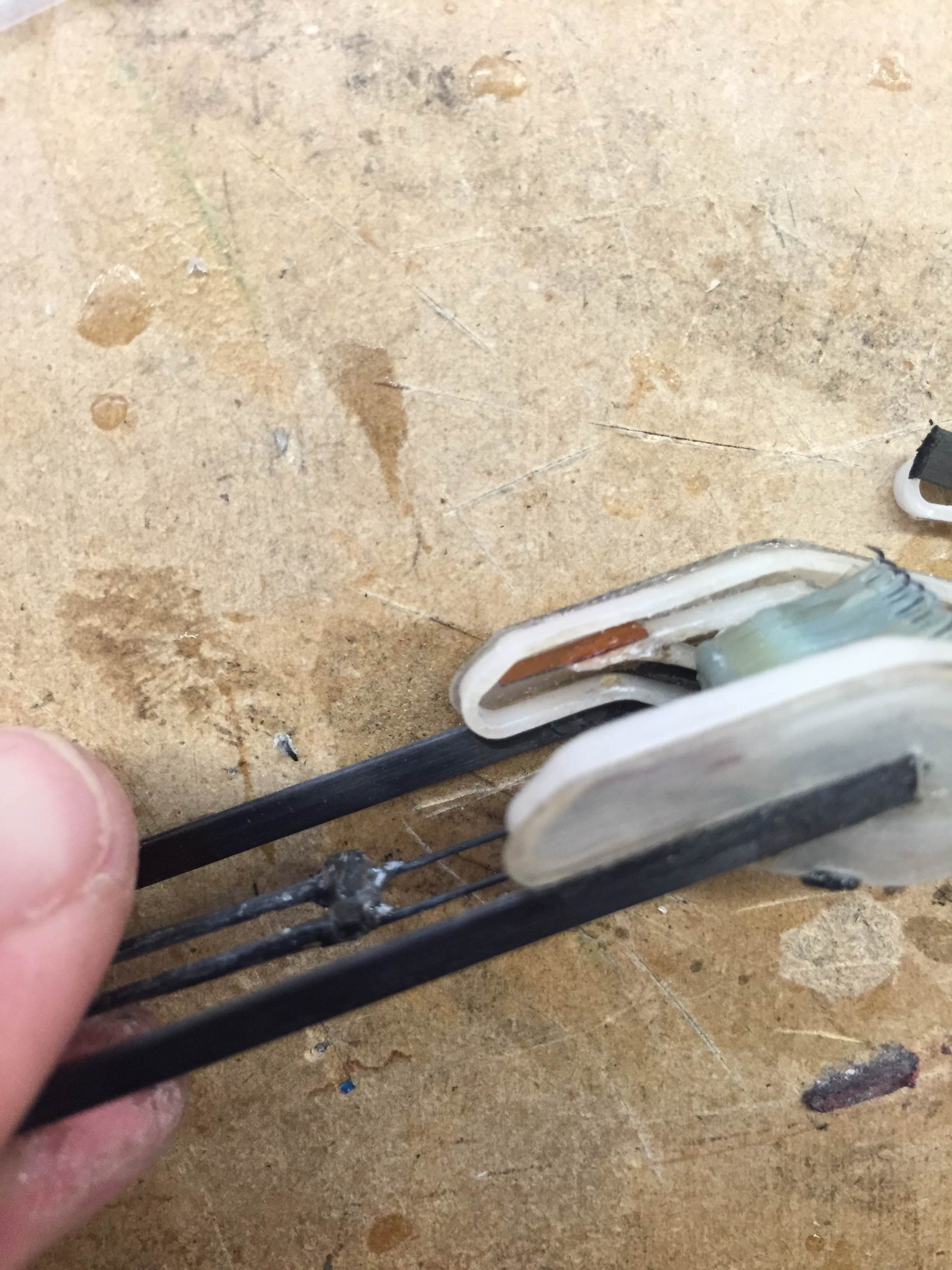
Thin kapton flexure. This significantly reduced the violent snapping at the bottom.
Monday, August 3
After a relaxing weekend at home, I got back to work today. I was able to finish most of the climbing frame during a productive morning session, then mounted the device to Crazyflie shortly after lunch. The whole mechanism weighed in at just over 10 grams, so it's on the heavy side but is still well within the acceptable bounds. I also think I can save some weight on the foot track mechanism by slightly re-building, and depending on how tests this afternoon go, will possibly just rebuild the entire mechanism with weight saving in mind (but preserving the same foot profile).
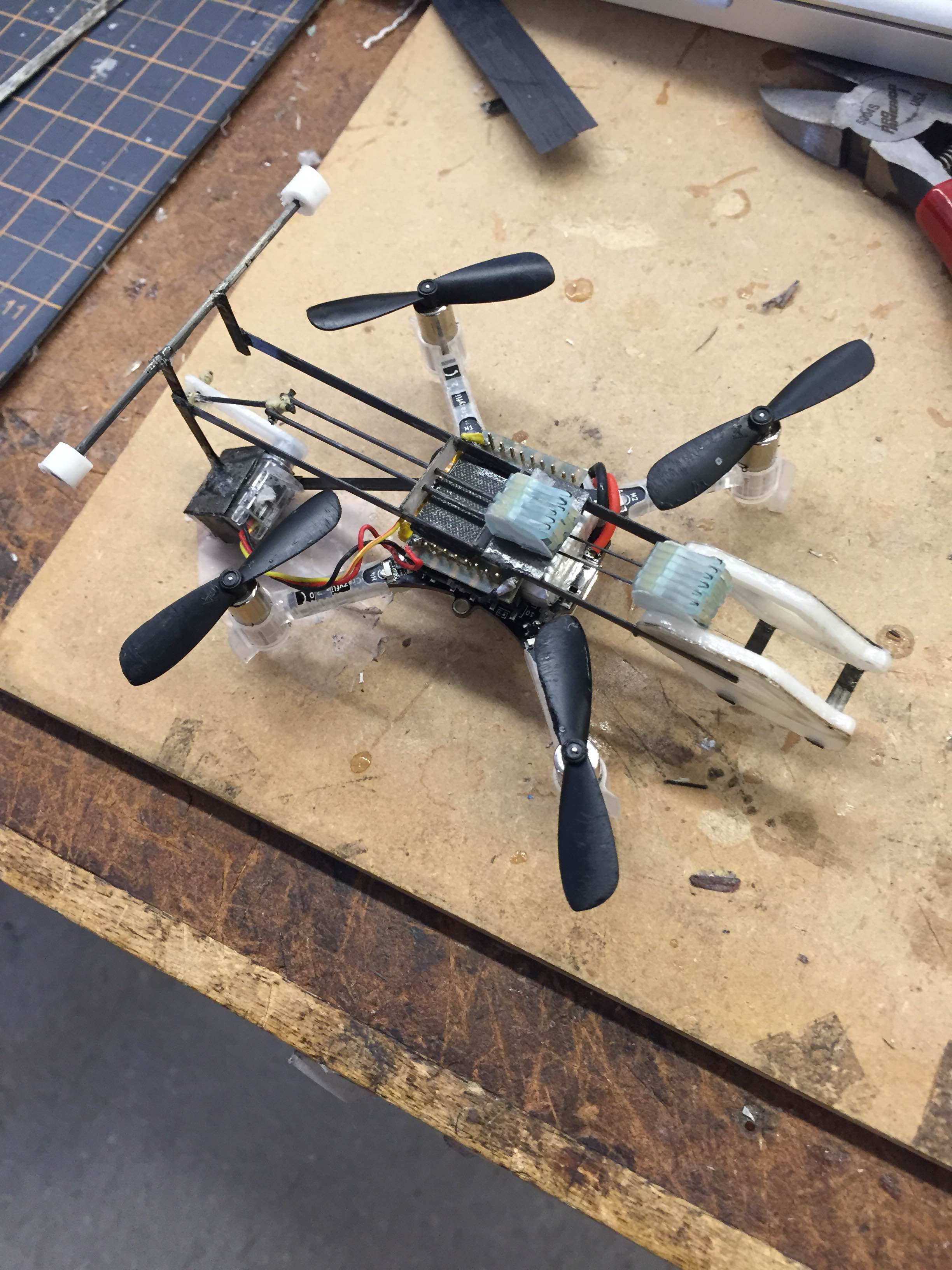
The much more photogenic climbing prototype. Note that it looks like a scaled down version of the larger prototype from last week.
When we tested this prototype, the load transfer at the top of the track was excellent, but the robot lost contact at the bottom almost every time. The first issue resulted from snapping the foot between the two tracks, which caused a vibration similar to that caused by the inchworm gait earlier this summer. When Crazyflie was able to hold on through this vibration (or catch itself) it would lose contact during the second load transfer, when the top foot is push diagonally up and away from the wall. Instead of bringing Crazyflie's chassis and by extension the bottom foot closer to the wall, it simply pulled the hook out of its asperity.
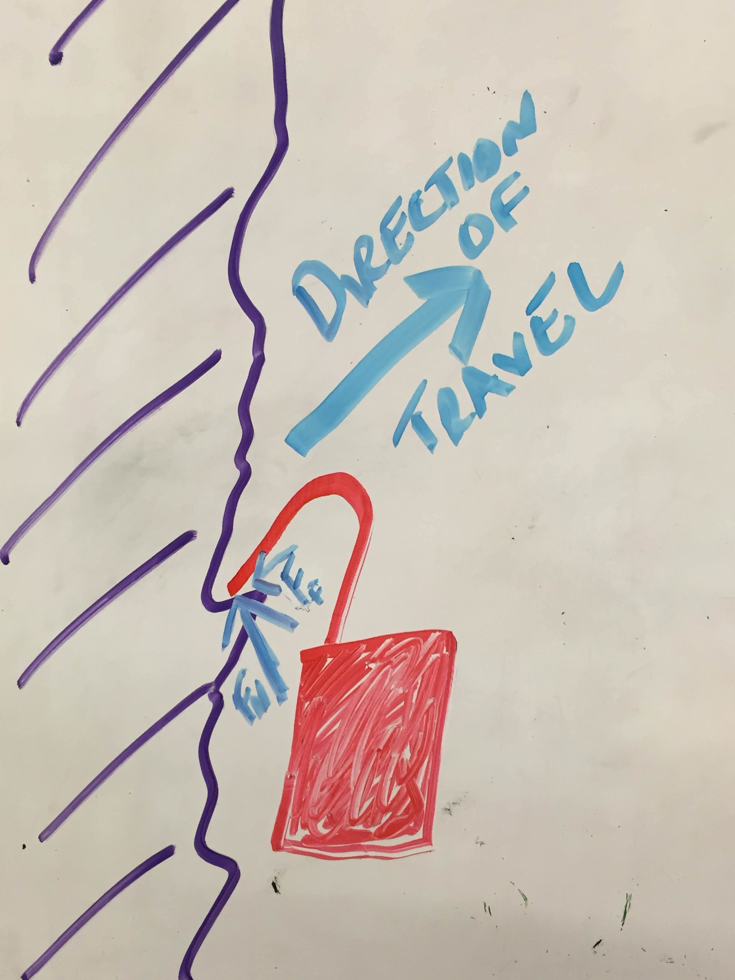
The problem is twofold; since the direction of travel is similar to the hook's incident angle to the wall, so the only force holding the hook against the wall is the small static friction between the hook tip and the wall material. Also, since the lower foot is mounted rigidly to Crazyflie's chassis, moving it into the wall requires overcoming a much larger inertia than moving the top hook away from the wall. The high speed footage of my tests showed that when the perch failed during this upstroke, Crazyflie had nearly perfect vertical acceleration down, and the upstrokes failed to affect the main chassis' motion at all reminded me of the classic "inertial tablecloth" demo used by most physics teachers.
After testing, I had a long whiteboard discussion with Morgan and Matt regarding how to alleviate both the vibrations from snapping and the issue pulling the hook out of the wall. Matt suggested a small flexure that could act as a one way gate or valve in the track to mitigate snapping, and I proposed a less passive mechanism to press the bottom foot into the wall when the top foot begins its upstroke. I will give more progress on these mechanisms tomorrow.
Week 6
Thursday, July 30
I got an email from Mark early this morning regarding my summer blog. He liked my presentation slide from last week's lab meeting, and suggested I use delrin instead of acrylic for the linear slides, and that we had some white delrin sheets lying around the lab. After investigating, I realized that I had actually mistakenly been using delrin, which explains why it was not cutting as cleanly as I expected in the laser cutter (I had been using the "3mm acrylic" settings). I finished assembling my slider mechanism, and realized that adding the slight angled tip at the edges of each stroke actually made the transfer between tracks worse. I will need to create yet another track mechanism that relies on more deflection, and still keep the overall stroke length down. The mechanism did end up looking pretty, and the carbon beams sat very flush with the fiberglass. It also kept the carbon incredibly square, and made aligning the mechanism very easy. I'm going to continue doing this with the remainder of my prototypes.
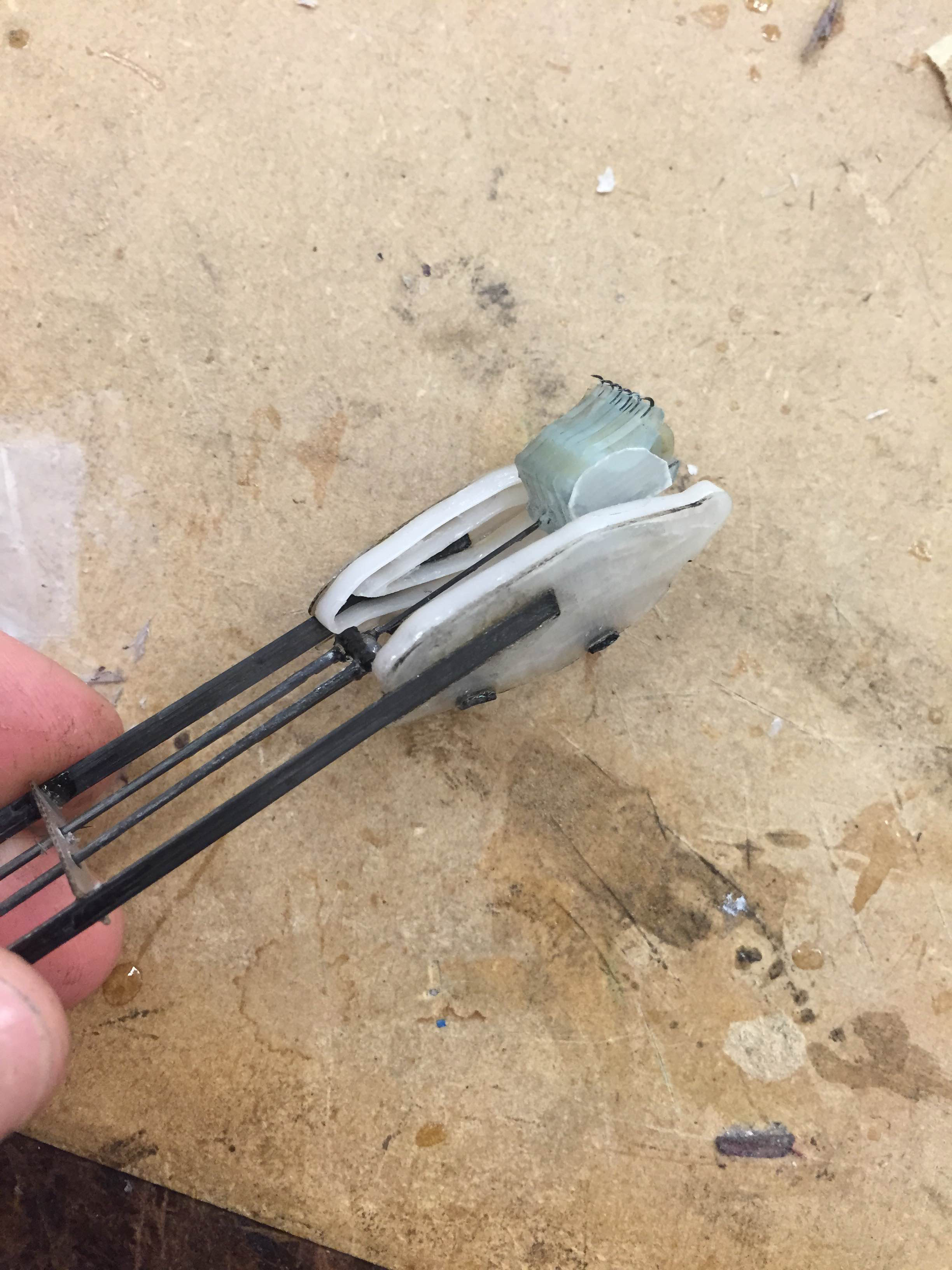
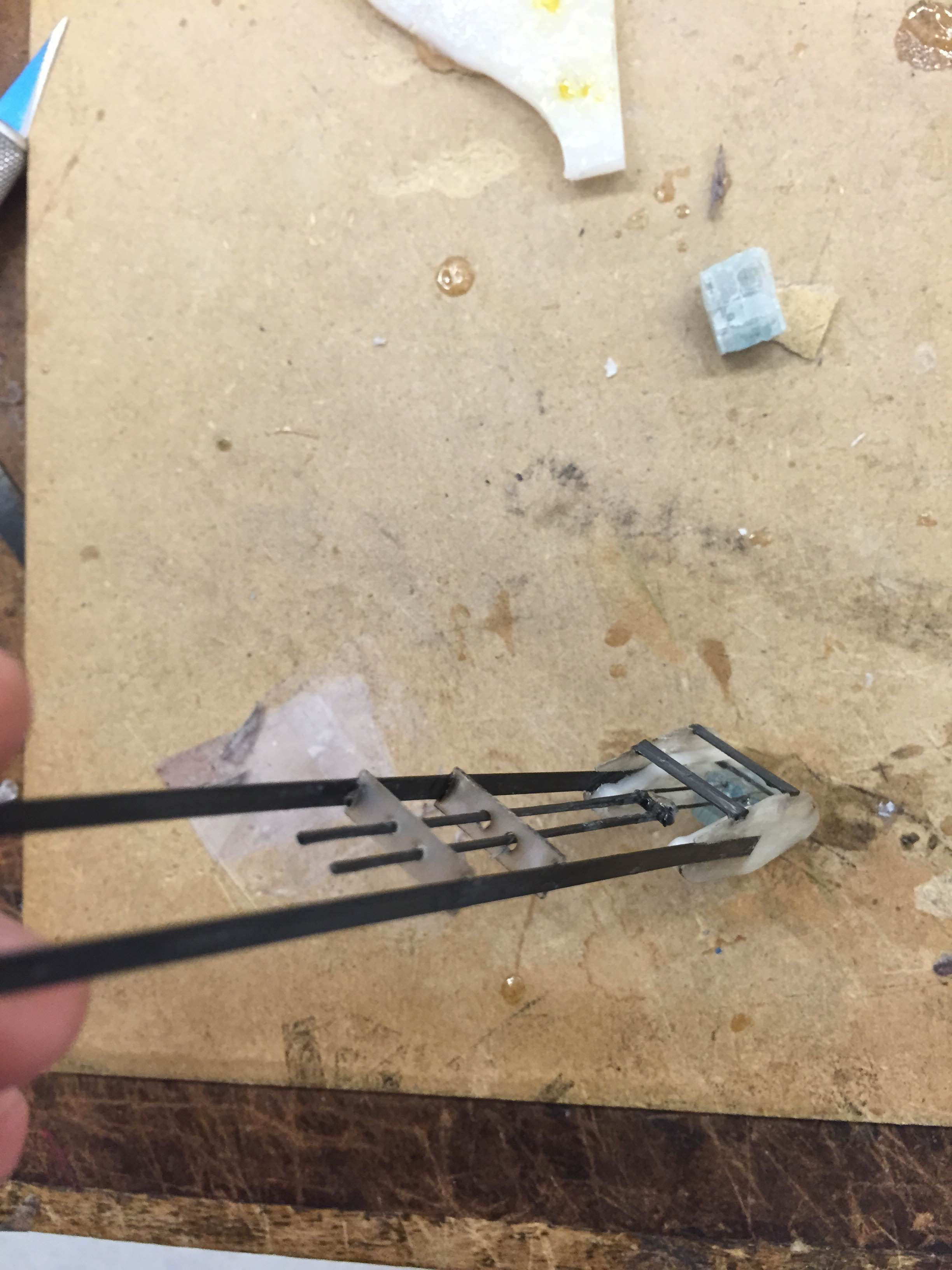
Assembled mechanism from this morning, with flush carbon beams and fiberglass slide bearings.
This afternoon was spent assembling a slightly modified version of the mechanism I made this morning. It is wider, so there's more deflection to snap the pin back into the correct track at the top. I also added a small rod so that only the end of the slider can deflect, which creates a much larger force than allowing the whole length to gently bend.
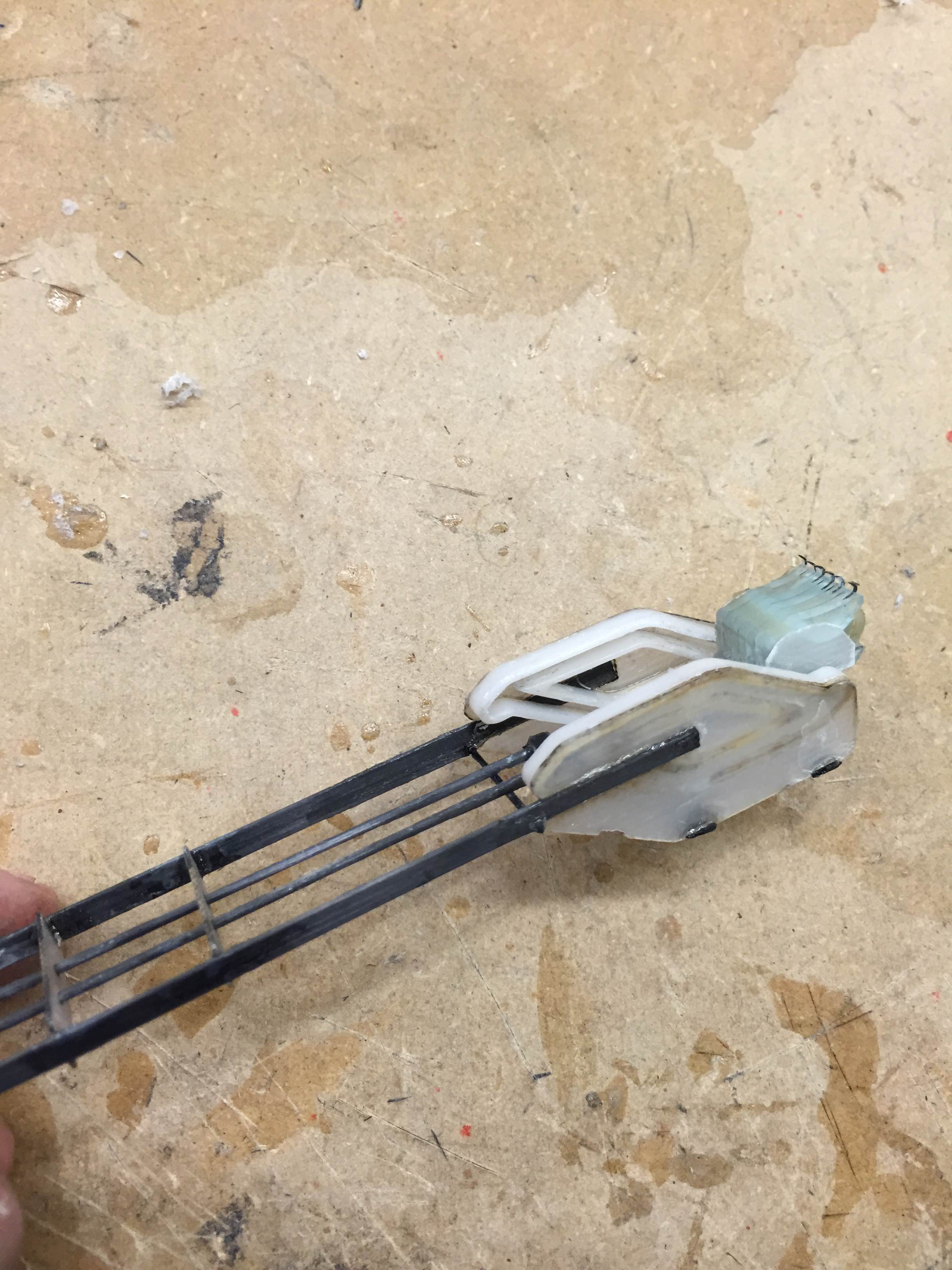
Newest prototype, which is visibly thicker. The rod mentioned above is right at the edge of the fiberglass track plate.
I'm leaving tonight to go home for a dental procedure and to see my parents, so I will resume work on Monday.
Wednesday, July 29
This morning, I tested the climbing mechanism and discovered a couple of flaws. While loaded, transferring the pin between the two tracks did not work smoothly enough. In addition, the servo we have been using was not strong enough to pull the weight of Crazyflie up the wall with the current servo arm length. I will almost certainly have to reduce the arm length in use, which means I will have to make a track with a shorter stroke. Conveniently, a smaller stroke will also lead to a much lighter track mechanism, which will alleviate some of the weight issues.
I experimented with a new track profile that should make the transition between tracks easier. I spent a significant portion of the day CADing and cutting/assembling this design. Hopefully, changing the angle at which the sliding pin changes tracks should allow me to have a narrower overall track since I will require less deflection to snap the pin from one track to the next.
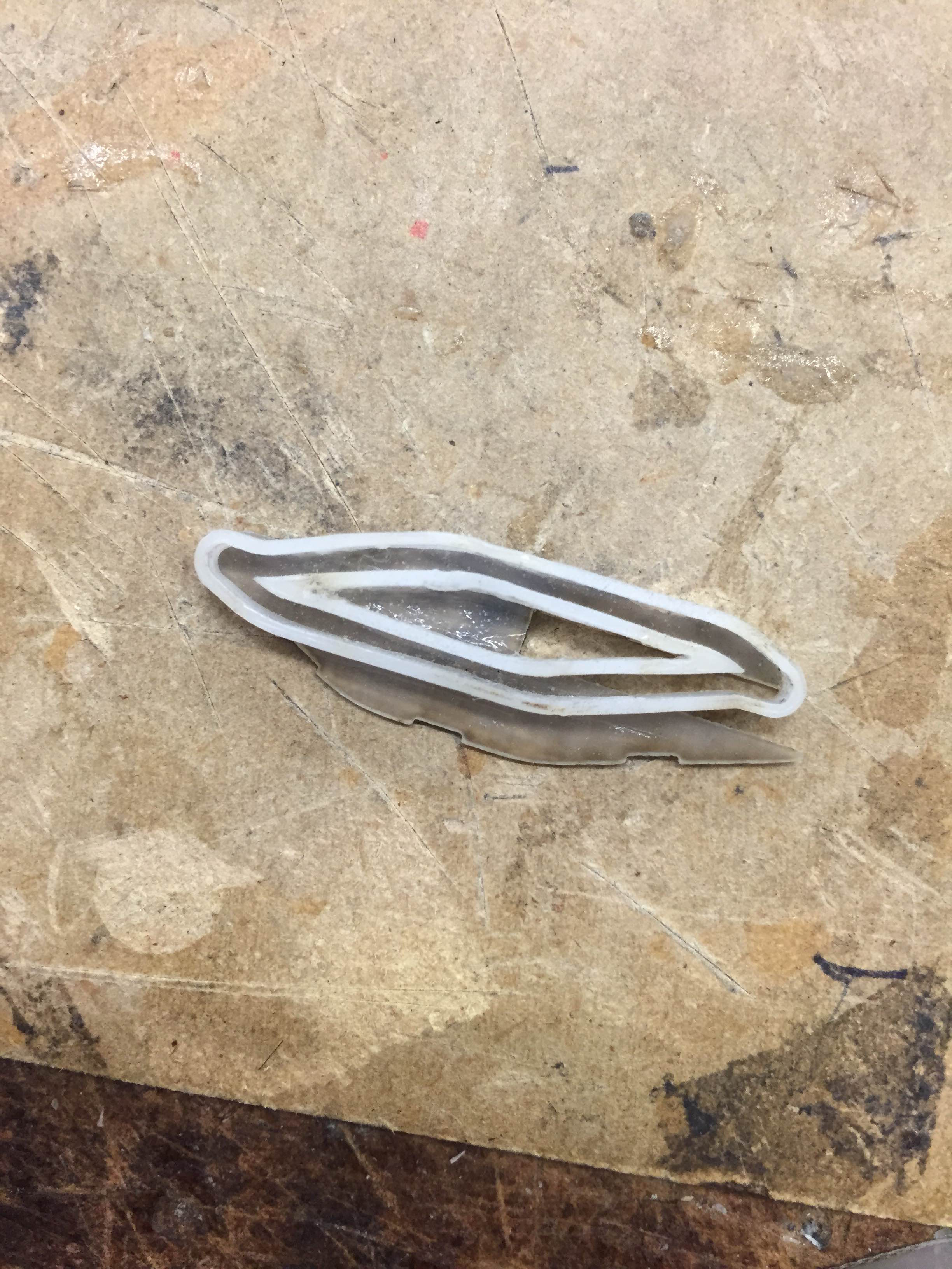
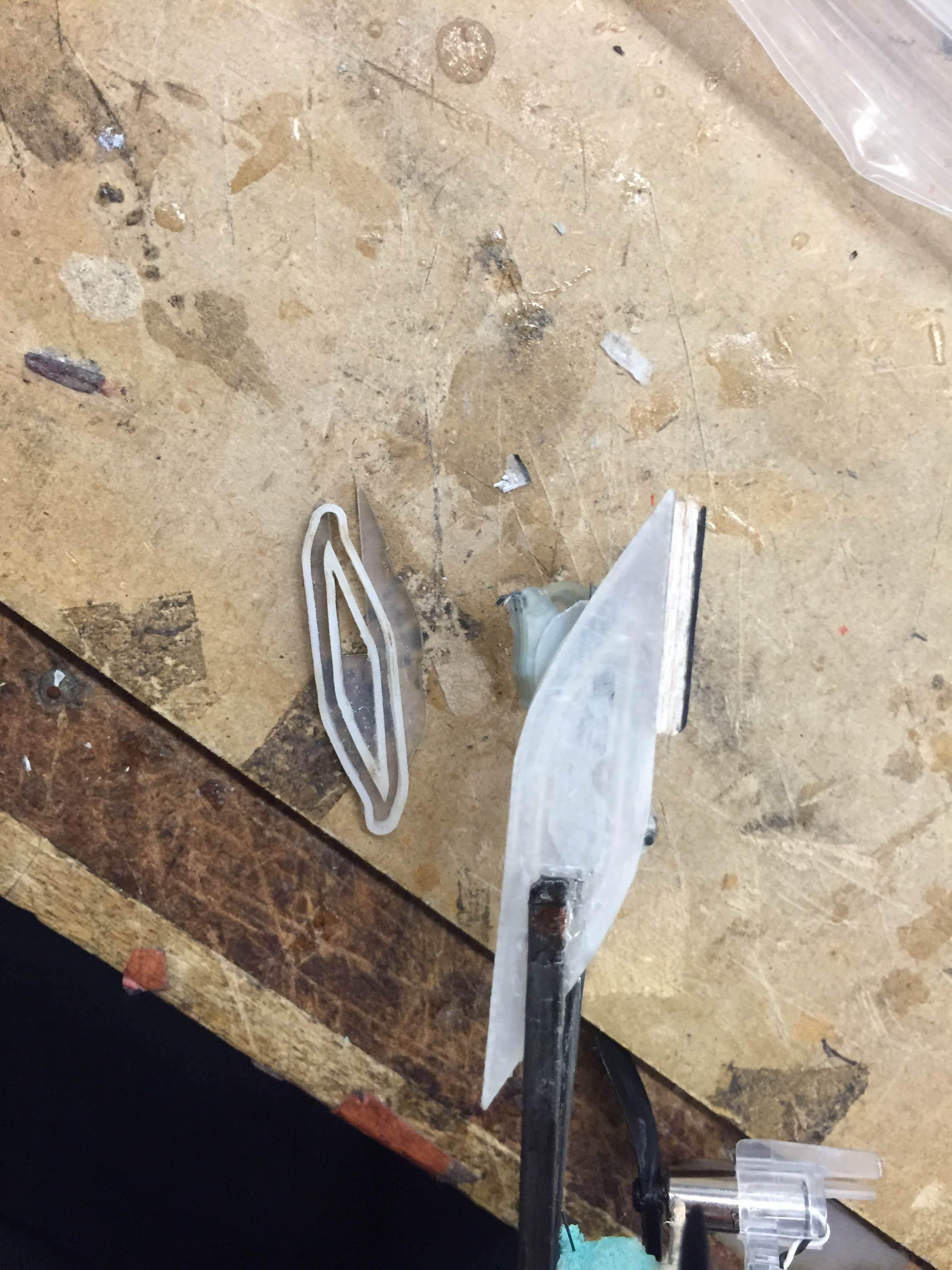
Left: The new track profile. In this image, up is the direction facing the wall. Right: New track next to old track for size comparison.
Since weight was such an issue last time, this track mechanism will be smaller than the last, and I'm attempting to integrate the support frame into the mechanism design. Ive chosen some 0.020" thick carbon beams that should sit flush with the 0.020" fiberglass, so I've tried to integrate them into the design of the slider back plates.
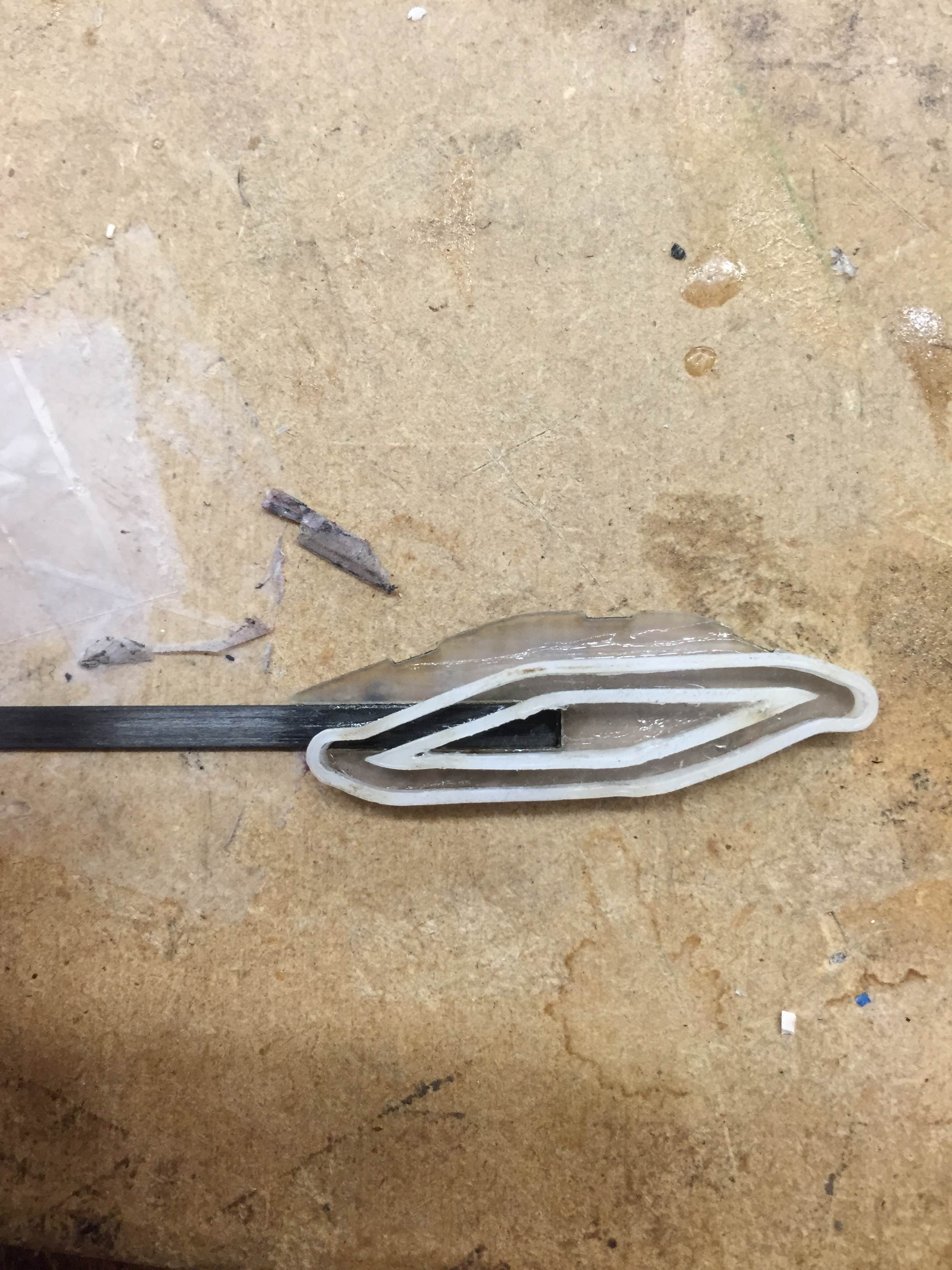
Carbon beam sitting flush against the back plate on assembled track
Tuesday, July 28
I spent today finalizing the first prototype of the new climbing mechanism and attaching it to Crazyflie. It took a while to iron out all the kinks, and I ended up with a massive mechanism that will almost certainly need to be downsized. I'm pushing the 15g payload limit, as this mechanism currently weighs over 14 grams, but I have a few areas in mind that I can definitely downsize. I will more than likely create a new track with a slightly different profile and smaller overall stroke length, which should reduce the length of the entire mechanism.
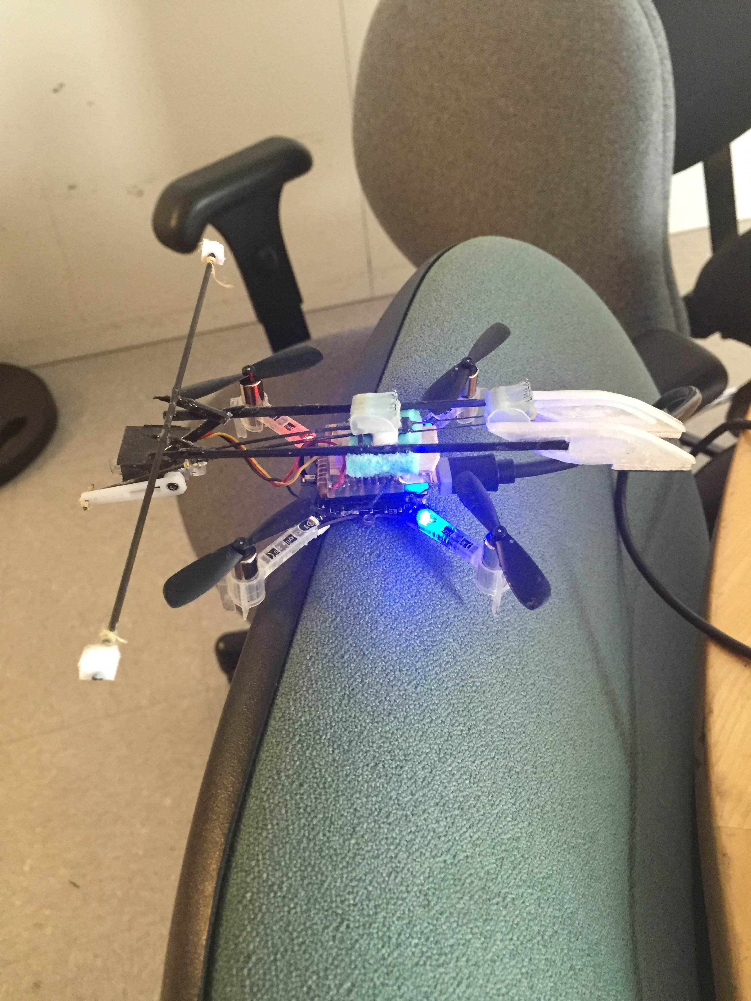
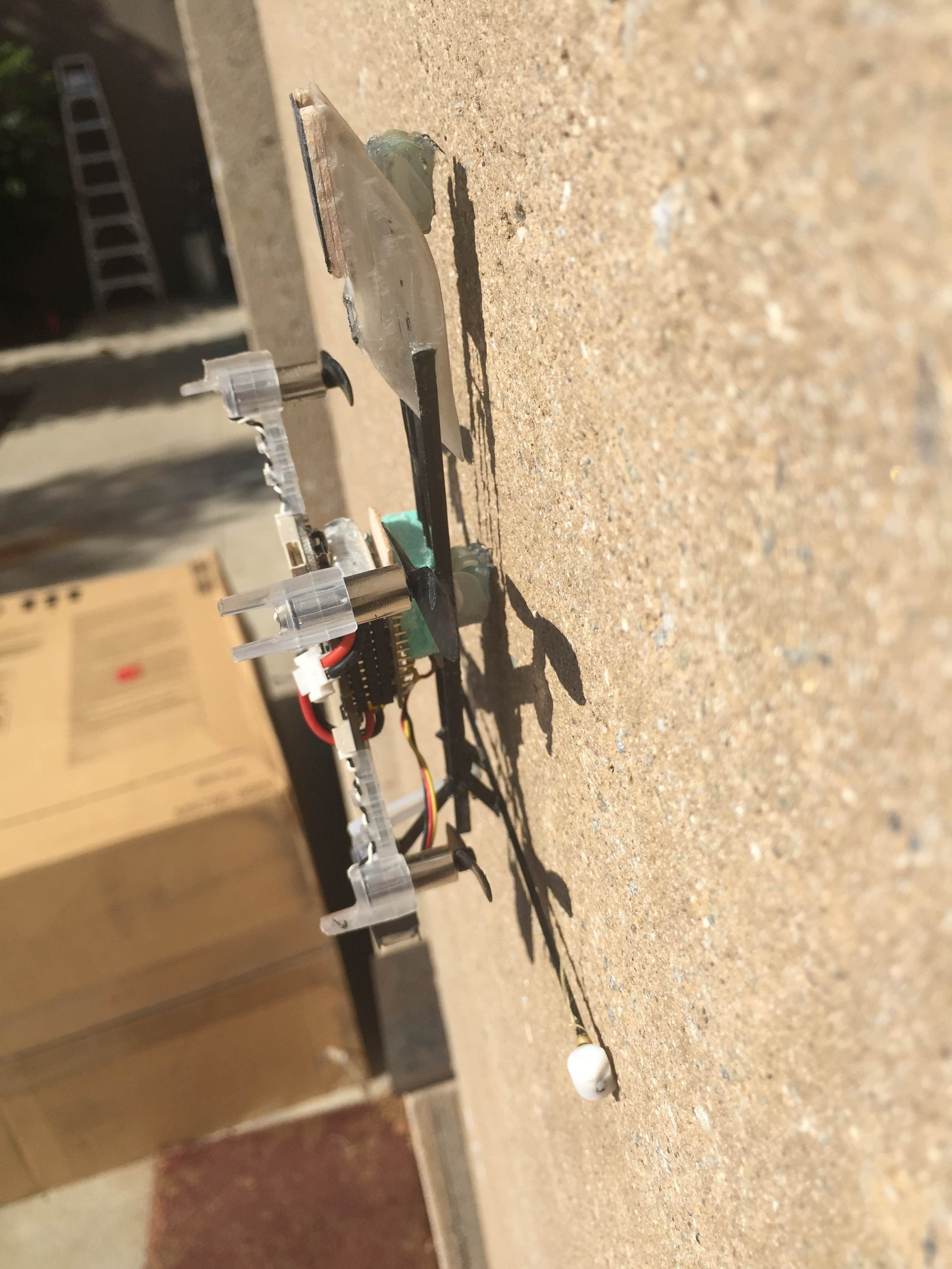
Left: Finished mechanism dwarfing Crazyflie. Right: A test hang on the wall outside.
Monday, July 27
I tested the lighter, fiberglass tracks and found them to have too much friction. I spend a while sanding them down and hacking at them with an X-acto knife and got them to slide a bit better, and eventually tried a light coat of teflon lubricant. The teflon helped some, but not enough to be workable. Also, as I predicted last week, the x-direction travel was not enough to cause the foot to "spring" between the downstroke side and recycling side, so I will create another version with more x-travel. I have been using three layers of 0.020" fiberglass, one as a base layer and two to create the track profile. Because the track profile is two layers glued together, the face is not very flush. This increases the chance that the pin will jump out of the track, and also increases the sliding friction (along with the fact that fiberglass doesn't laser cut that cleanly). I will make more tracks this afternoon with a fiberglass back, and a single layer of thicker acrylic to create the track profile. It'll be heavier, but should be a huge functional improvement.
Updating this on Tuesday morning. I had a pretty frustrating afternoon. I did create the track pieces out of acrylic and they work very well, but midway through the afternoon my laptop crashed and wouldn't start up again after many attempts and many hours. David, who knows a lot about computers (and most other things) said he thought it was a hard drive failure. I spent about an hour trying to get the laptop up and working again to no avail. It is now back from the dead as of Tuesday morning, and I backed it up to an external hard drive. Hopefully the issue doesn't persist, as it seems to be working alright this morning.
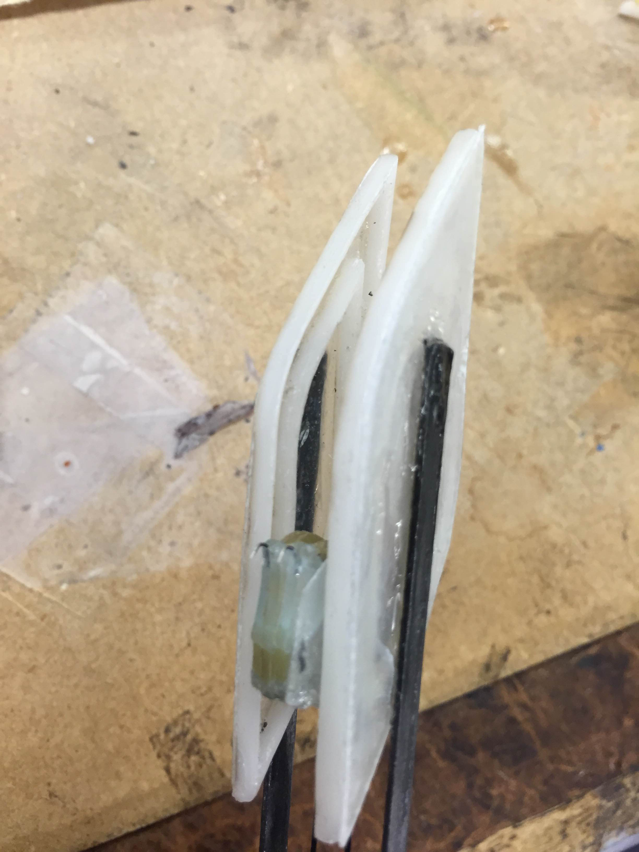
Acrylic slide track, which is visibly deeper. The laser cut on gave the acrylic a very smooth edge, so sliding is quite good. I need to modify the rest of the mechanism to accommodate a wider foot.
Week 5
Friday, July 24
This morning, Morgan presented his perching work at lab meeting, and I got to present some of my perching and climbing work as well. I made some cool figures that I felt demonstrated some of the problems with our old climbing method and clearly depicted how the new mechanism is supposed to work, so I've included them below.
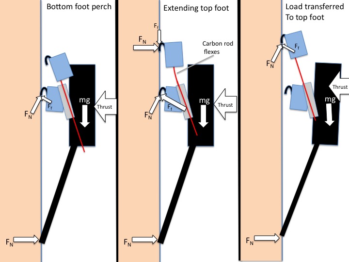
The main problem with our previous design was the large thrust required to keep Crazyflie from falling off the wall
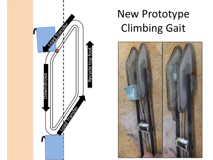
This slide clearly shows the foot path of the new mechanism
After eating at this week's installment of MERL Barbecue, I spent the afternoon creating a lighter, smaller prototype for the tracks. Each track unit from yesterday weighed in at 1.21g, whereas these4 two track units combined to be 1.11g, since I included a large hole in the middle and reduced the overall size. Since I cut the outer and inner track pieces so thin, these were extremely difficult to assemble. I ended up having to sand down a lot in order to make them convincingly smooth, although I think they still might have some issues. I'm also concerned that they do not have enough x-direction travel to cause the foot to "spring" back and forth between the climbing and recycling tracks, so I might have to remake them with more x-travel so the carbon rod deflects enough.
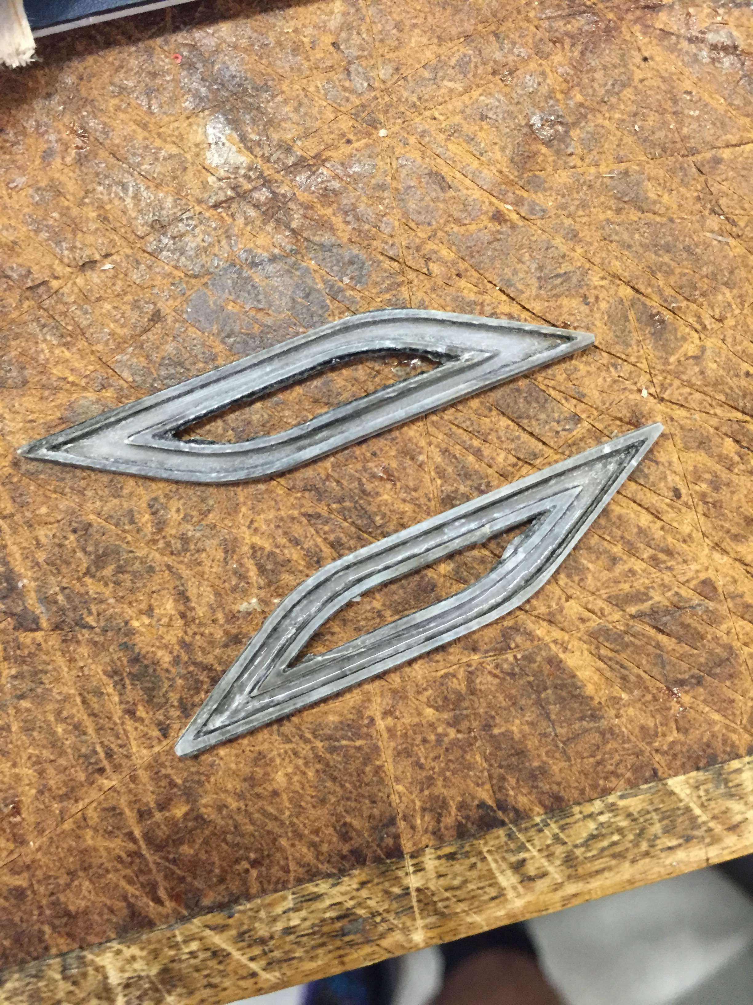
New slide mechanism, still requires more sanding.
Thursday, July 23
I spent most of the day prototyping the new climbing mechanism. This meant a CAD session in the morning and a trip to the TLTL to laser cut some thin fiberglass. I had thought about using the UV laser down the hall for a really fine cut, but Arul said it probably wasn't necessary. I had to sand the edges of the cut fiberglass down to remove the ash, but after that the small carbon pin slid pretty smoothly through. I was initially concerned that the mechanism would jam, but when actuating it by hand I had no issues.
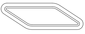
Drawing of the foot channel. The foot has a pin that travels between the two tight lines.
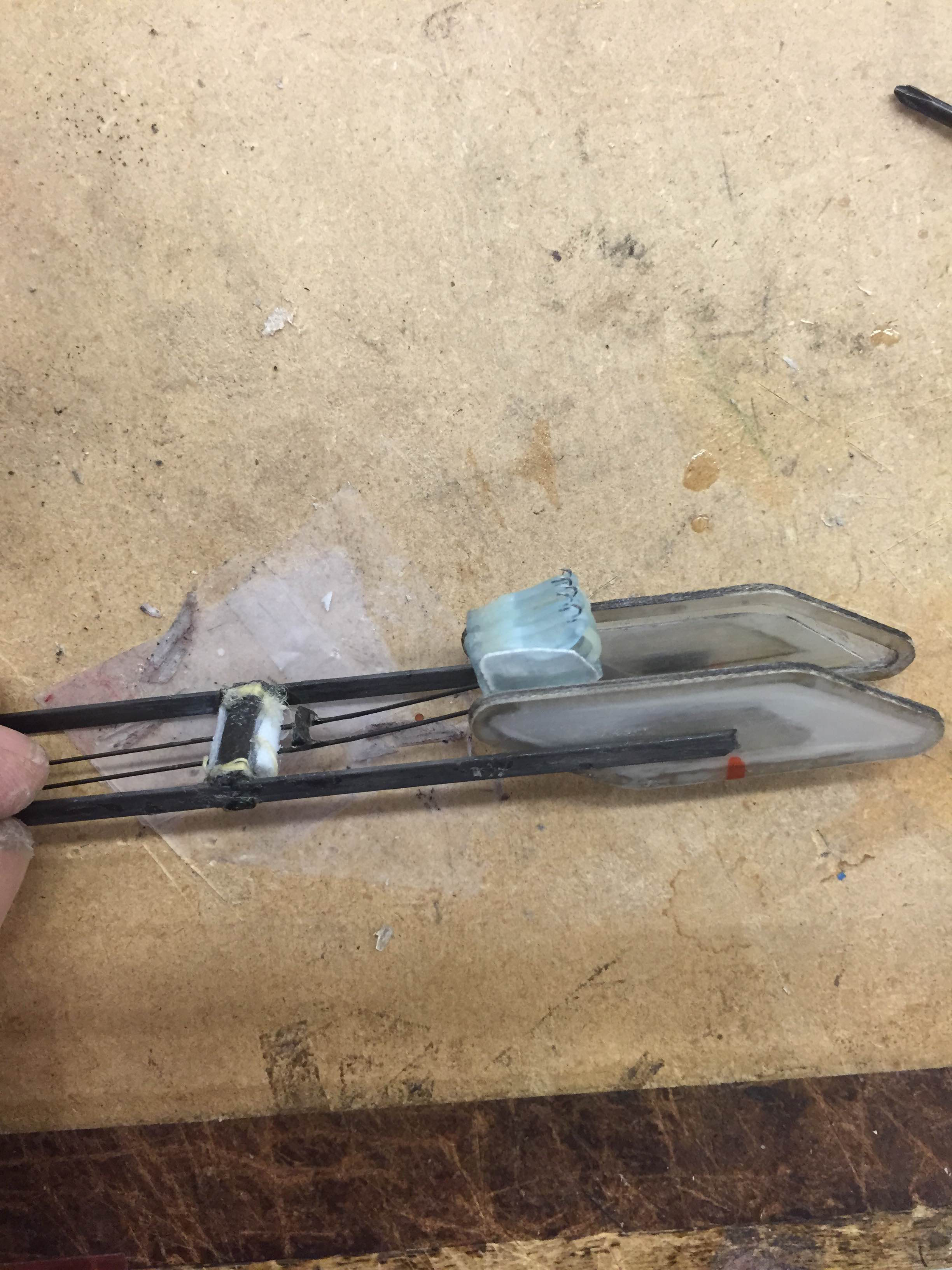
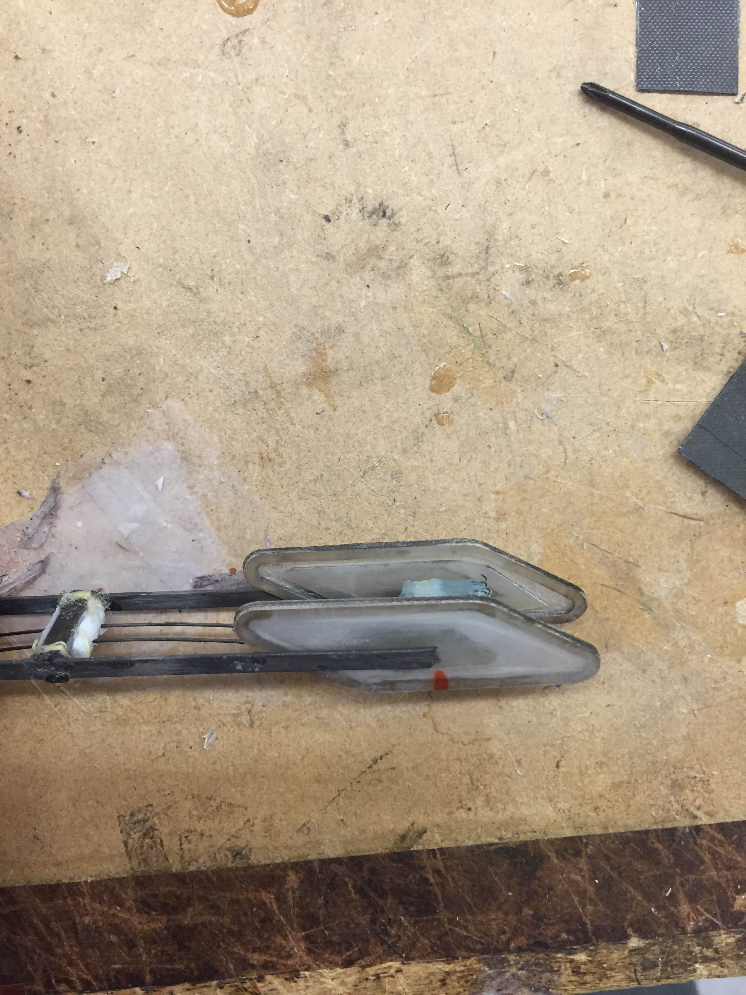
Foot traveling in the "engaged" half of the track (left) and the "disengaged" half (right). In the both pictures, the deflection of the linear slides that restores the the foot is visible.
In order to achieve the exact foot trajectory we want, the foot is attached to a pin that slides through the fiberglass channel. This is actuated by thin linear slides, and the deflection of the linear slides caused the foot to spring between the "engaged" track while pulling Crazyflie up the wall and the "disengaged"track while recycling, while Crazyflie is perched on its static foot.
I was very encouraged by how functional this prototype was, and I'm hoping to have a fully functional prototype by early next week. I'll continue experimenting with different foot trajectories to create the smoothest gait. The 0.020" fiberglass is relatively heavy, so I might try to shave some weight with the new slider designs wherever I can. David also mentioned something at the end of the day about servo hacking for full continuous rotation, which I've heard of and seen done but never done myself. Apparently, the servo I've been using should not have a physical stop, yet it jams consistently at the same angle, rendering it unhackable. I might investigate to see if the gearbox is damaged and possibly hack a servo for continuous rotation using Crazyflie, which could be useful for this project or future research endeavors.
Wednesday, July 22
Today was an incredibly productive day. In the morning, I brought Crazyflie all around campus and tried to find a suitable perching/climbing surface to film a video for the MAST report that is due soon. After I was unable to find any truly great surfaces on Stanford's buildings, I decided to use the roofing tile that Hao had reinforced with superglue that was lying around the lab. The tile had an abundance of asperities which made it ideal for perching, but no deep ones that would catch on feet as they slid upwards, which made it ideal for climbing as well. Then got video of Crazyflie successfully perching and climbing for the first time.
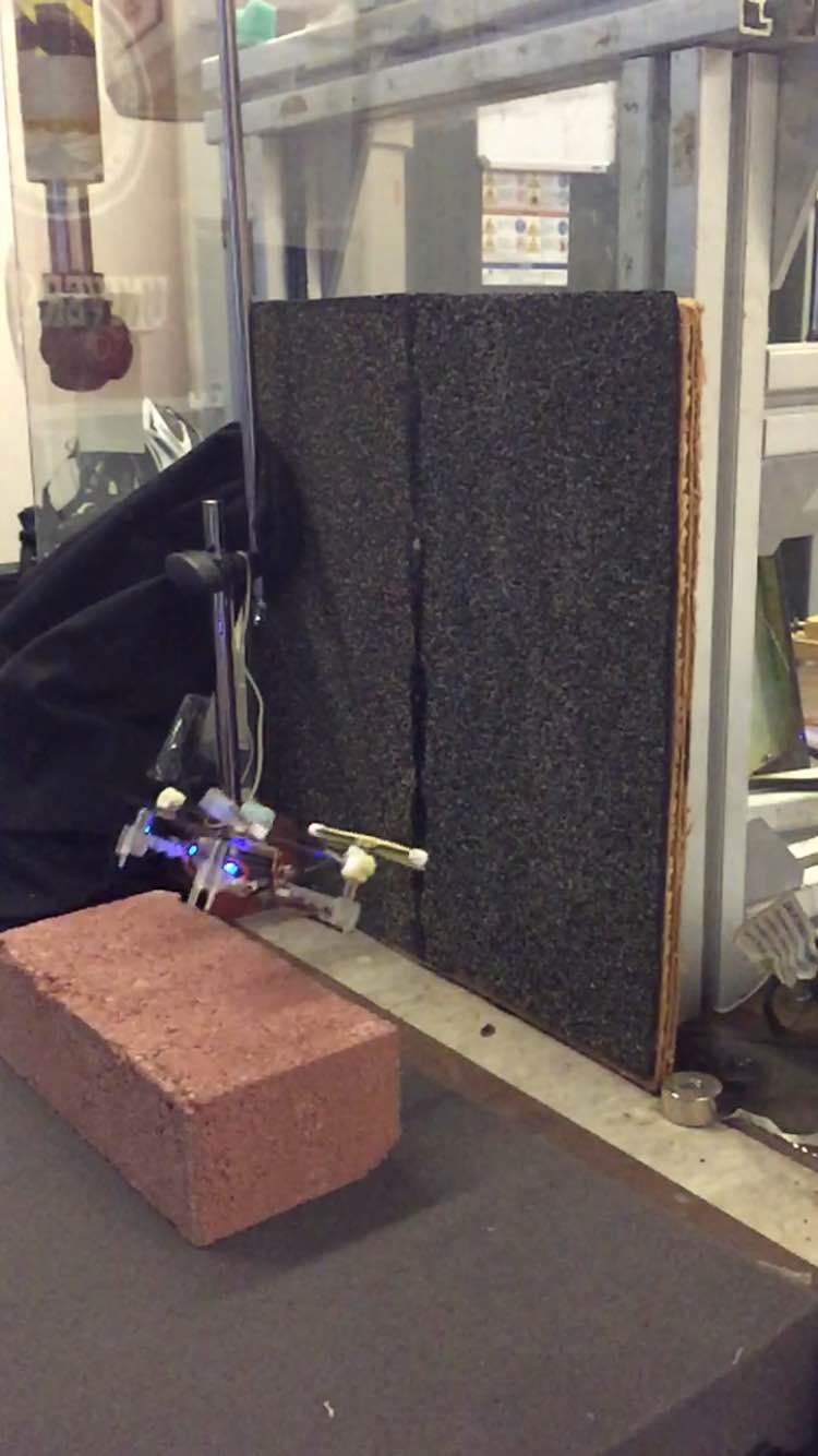
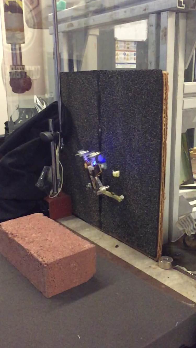
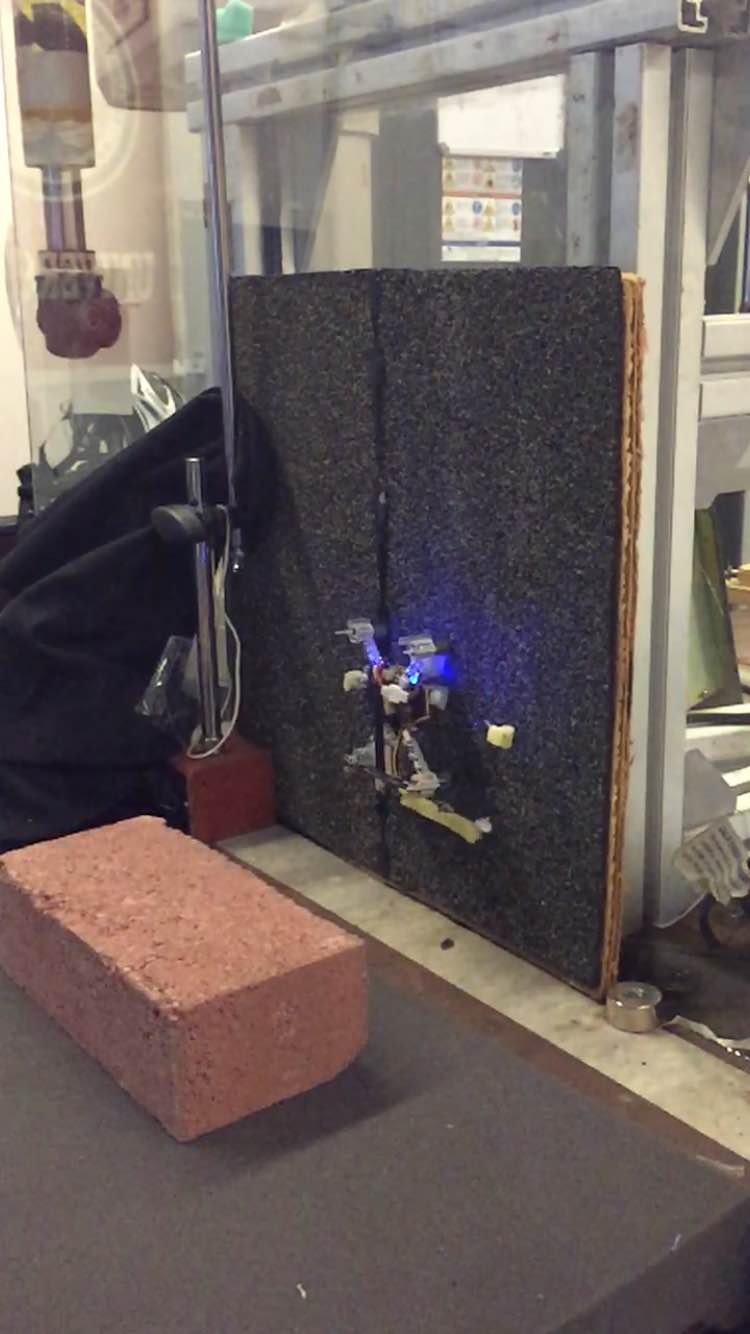

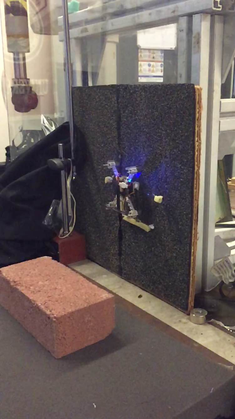
Perching and climbing.
After getting this video, I came up with what I feel is a very strong design for the next version of the climbing mechanism. It utilizes a pin and slide channel to crete the exact foot trajectory that Morgan and I want, and I will cut the channel with the laser, so the foot trajectory will be highly tunable. I spent the afternoon beginning to prototype this and talking with Arul, David, and Elliot about gecko-adhesive gloves they are working on.
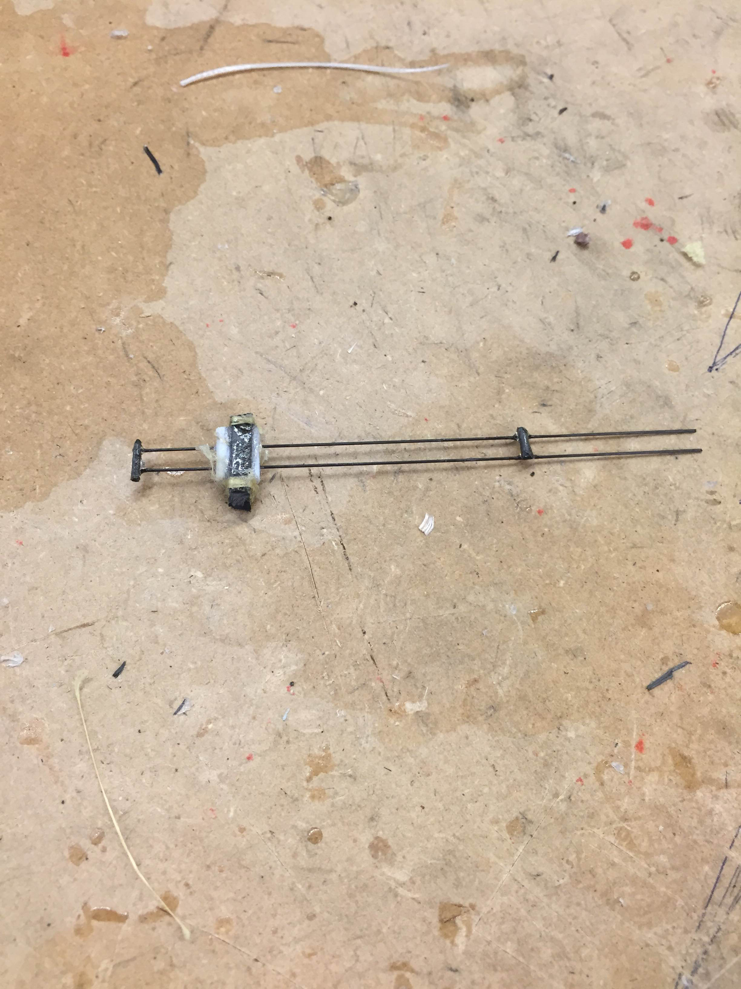
Linear slider for new mechanism, built narrow to fit between rotors.
Tuesday, July 21
I started the day by trying to get more perching videos, but did not have a successful perch all morning. I eventually decided the SDM feet on Crazyflie had degraded to the point of being non-functional, so I got some more and mounted them. In the afternoon, Morgan was using the laptop in the office for his perching/takeoff experiments, so I focused more on creating a linkage design for the next version of the climbing mechanism. I was experimenting with using four bar linkage, and even created a small prototype out of fiberglass and carbon rods. However, the prototype did not look particularly promising.
I also uploaded two of the videos taken yesterday, so here is an attempt at perching and climbing and the same perch in slow motion from my iPhone's 240fps high-speed setting.
Monday, July 20
I spent all of today debugging some issues I was having with Crazyflie's code and filming perching/climbing attempts. In the morning, Morgan and I worked through some communication issues where Crazyflie would not fire its rotors, but would actuate the servo in an attempt to climb. Morgan stripped down a lot of unnecessary, vestigial pieces of code (some perching recovery methods for instance) and that seemed to resolve the issue. We filmed Crazyflie attempting to perch on the wall outside for most of the afternoon, and had a few successful perch attempts but did not successfully climb. Using the high speed camera on my iPhone was really helpful in diagnosing failure and making minor adjustments in the perching maneuver, but my phone's battery died before I could upload these videos.
Morgan and I also spent some time talking about the ideal climbing gait and possible linkages to create that gait. I will definitely have to get creative with my linkage design for a rebuild, which will probably start later this week. We also noted the importance of having a very compliant mechanism for perching while maintaining rigidity for climbing, so the next version might feature a fully rigid climbing/perching mechanism that is attached with some sort of foam or other springy material to the Crazyflie frame.
Week 4
Friday, July 17
Crazyflie climbed successfully for the first time today. I was able to get Crazyflie to climb all the way up the brick inside while spinning its rotors at low speed (about 1/2 normal hovering thrust). While this method is terribly energy inefficient, the rotor thrust towards the brick was enough to counteract the small vibrations that were causing the feet to lose their hold on the wall. For the future, we will definitely have to redesign the climbing mechanism so that robust climbing is possible without having to spin the rotors. Crazyflie also perched successfully several times outside, so hopefully on Monday I will be able to get a video of it perching and then climbing. I spent a lot of the day rebuilding parts of the climbing mechanism since spinning the rotors during a failed climb caused a ton of damage. The end result is that the added frame is more sturdy and space-efficient than it has ever been, which will be useful going forward.
I also thought a lot about new linkage designs for a rebuild, and I think I'm close to a final design. The most difficult constraint to overcome s the use of a servo rather than a continuous rotation motor, but I'll probably draw ups some designs either this weekend or Monday.
There was also a lab meeting today followed by MERL Barbecue. I realized how big a task it will be when we have to cook for all of MERL in a few weeks (there are a ton of people). The whole atmosphere of everyone outside eating burgers was lovely though, and it was nice to talk to some of my friends from nearby labs.
Thursday, July 16
Crazyflie is getting way closer to climbing successfully. I got some really cool high speed video of climbing and failing today that I might upload later. I also added a massive outrigger on the front that helps with perching from flight. We successfully perched once outside, so hopefully we can get a quick video of perching and taking a couple of climbing steps tomorrow. Inside, I was able to get 4-5 steps in a row on the brick, and learned a lot about how climbing failure occurs from the high speed video.

Crazyflie perched with outrigger
When the bottom foot is being dragged upwards, the hooks curl under as they interact with the wall. This force is transmitted to the Crazyflie chassis through the soft polyurethane, which causes the whole copter to vibrate and bounce. These vibrations can cause the top foot to lose its hold on the wall, allowing the quadcopter to fall away. On each successful climbing step I observed in the high speed footage, the top foot either held on through these vibrations or fell but successfully regrasped lower on the brick. This means that the current gait doesn't support robust climbing, so I might revisit using a different type of linkage next week.
My new linkage design will likely be based on replicating or emulating the foot trajectory used by spinybot, which pushed the foot into the wall to engage, pulled down in the plane of the wall, then recycled by pulling the foot away from the wall (preventing the non-active foot from interacting with the wall).
Wednesday, July 15
I continued prototyping and testing. All of my prototypes from today and yesterday have looked pretty similar to the one from Monday. Here is what I ended up with at the end of today:
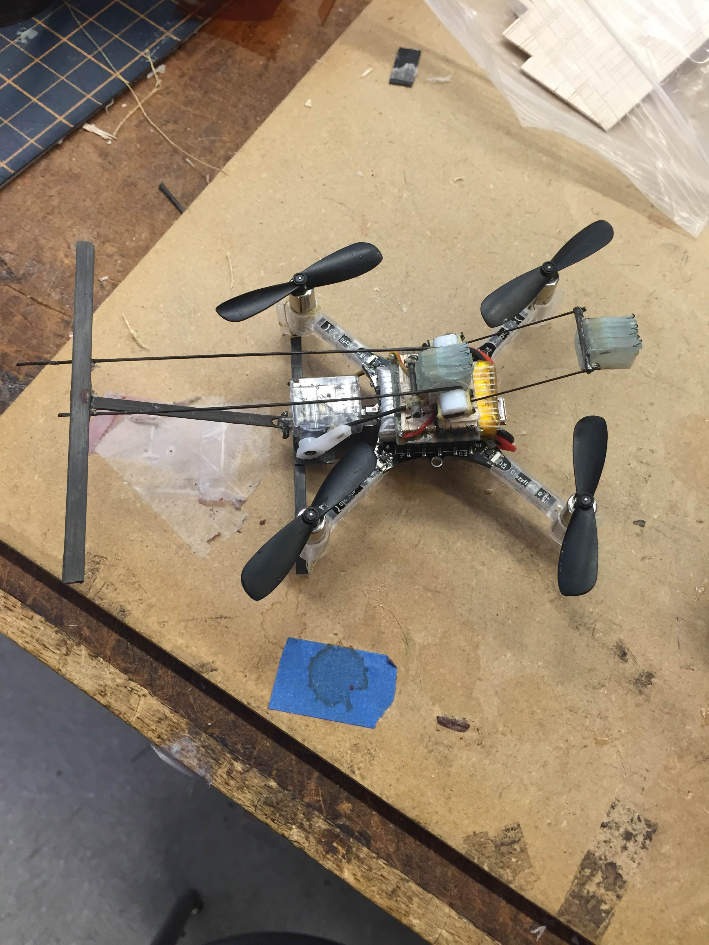
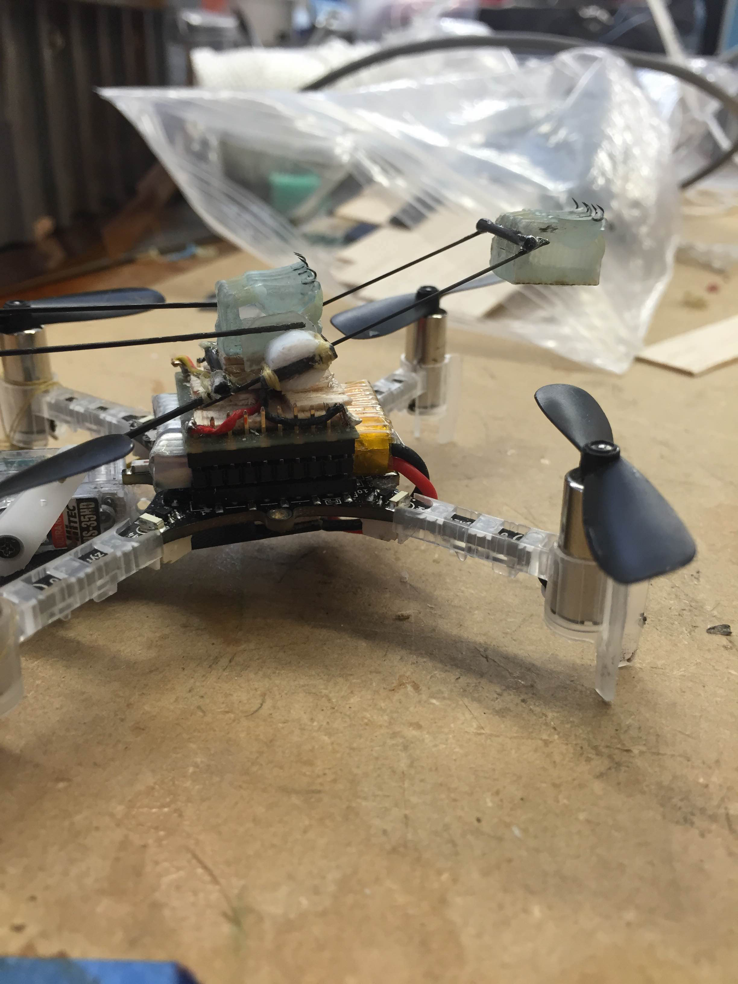
The previous version took 3 steps on a brick in the lab and two consecutive steps outside on the wall. The problem seems to be that the top foot presses the bottom foot off the wall on the upstroke before the top foot engages. Since the engagement is associated with pulling downward, Morgan suggested I use more flexible rods for the top foot, so you can see in the images that I've chosen some truly tiny carbon rods. The previous iteration had slightly thicker (but still compliant) rods, so hopefully the extra compliance helps prevent Crazyflie from pushing itself off the wall. I will probably test first thing tomorrow after letting the glue cure overnight. It's getting really close, so I'm hoping to climb by the end of the week.
Tuesday, July 14
I spent the entire day today testing and prototyping. One of my prototypes was able to climb two or three steps in a row on occaision. The fixed tail worked better than expected and the load transfer technique of pressing into the wall worked sometimes. I will be revising prototypes to incorporate a longer stroke length so that this effect is more pronounced, and there is a more defined transfer of the load between the top and bottom feet.
Monday, July 13
This morning I started by investigating the mini kapton springs I created on Thursday. I wanted to find the failure load, so I asked Katie to help me setup the ATI force sensor and Matlab script she had been using for her microtug project. I found that the 10mm springs failed at ~1.4N and the 15mm failed at ~1.2N (both of which I found surprisingly large but not unreasonable). Since the sensor was logging forces vs time, I did not establish a Force-Displacement curve, although they felt as if they had a non-linear, decreasing spring constant profile, which could make them useful for load sharing.
One Morgan arrived, I briefed him on the work I had accomplished and discussed the direction of perching/climbing moving forward. There is a MAST report due in two weeks, so I will be focusing mainly on climbing for a while, then possibly move back to foot design. I spent the latter half of the day revising and testing prototypes.
The newest design features angled linear slides that press each foot into the wall when it needs to be activated. It will feature a fixed, rigid tail, which is an upgrade since extra play in the tail caused previous designs to fail. This is a more direct approach to transferring the load between feet, and I like it as it's more simple.
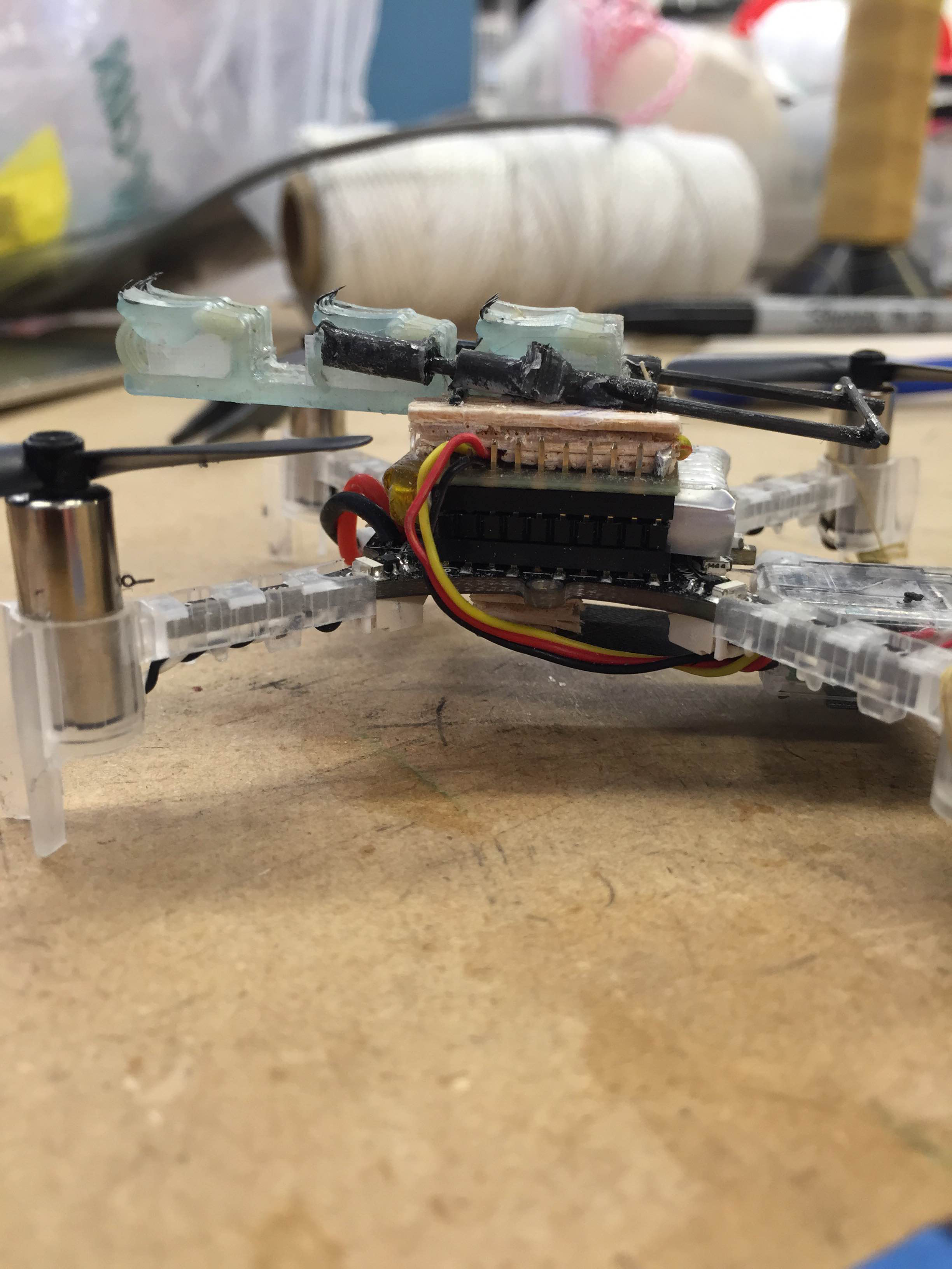
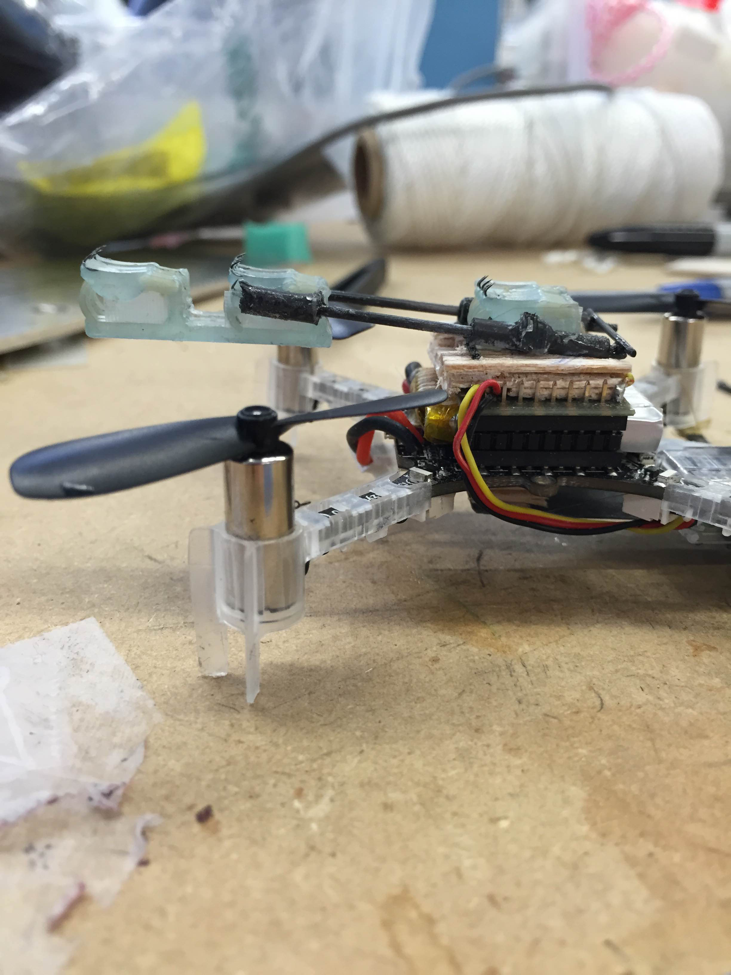
Left: Bottom foot engaged. Right: Top foot extended, engaged.
Week 3
Thursday, July 9
This morning I continued reading through Mark's summer blog and talked with Hao about spine-based gripper design. He suggested I look at the old Spinybot feet and the interesting SDM-created feet that it used. I read the 2006 ICRA paper on Spinybot, and noted its interesting foot linkage. I've also started thinking about ways to make the construction of non-SDM spiny feet more efficient. I think that I can possibly build on some of the work Mark Cuson did last summer.
Before lunch, Hao gave me some more foot-design papers to read, and I experimented with a Shape Deposition Manufactured foot on Crazyflie. The foot was a bit heavy, but looked very effective at gripping the wall and had no issues with getting "jammed."
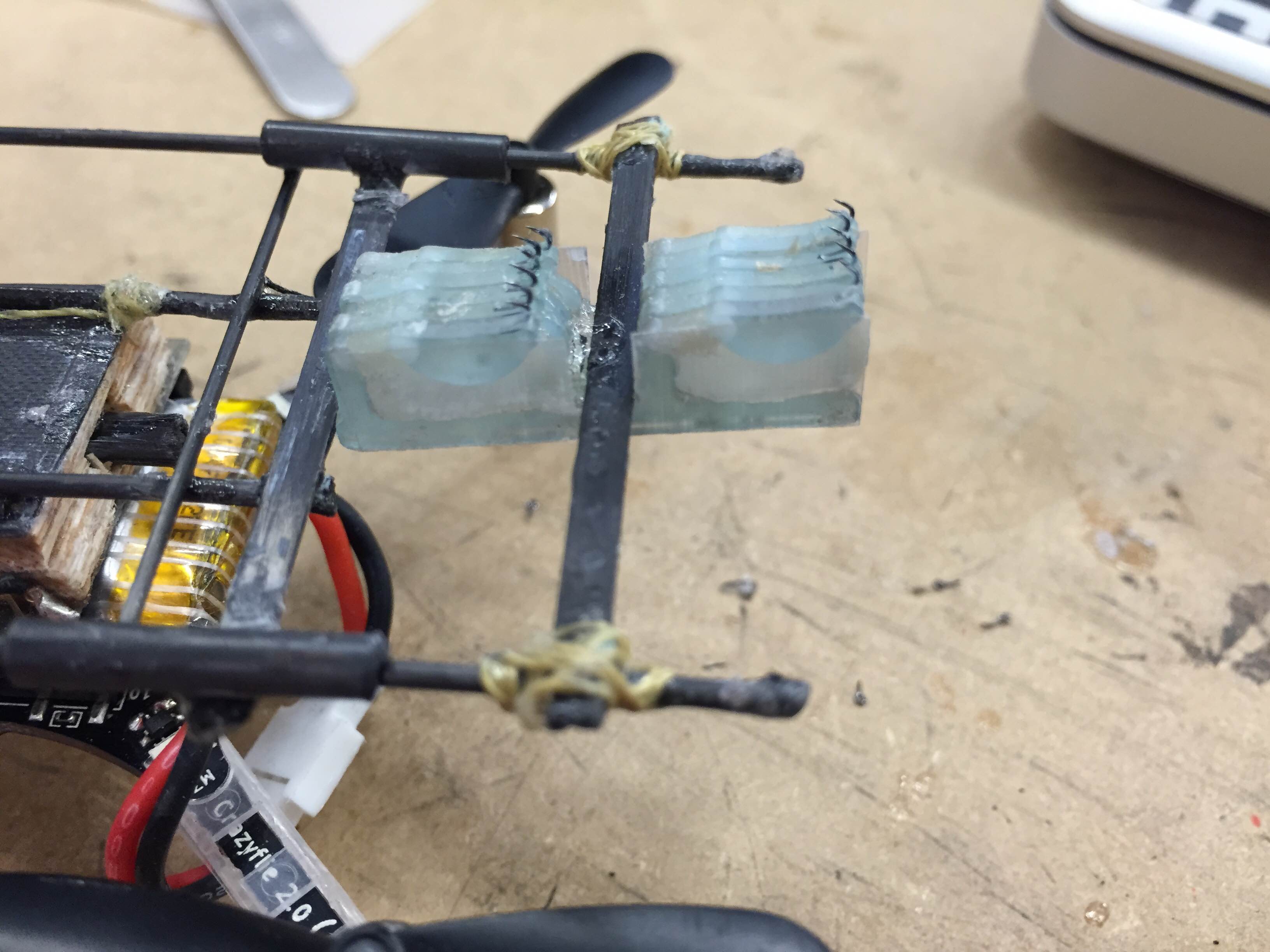
Hao and I discussed ways to reduce the mass for this type of gripper, and a relatively simple way would be to replace the thin, vertical "sheets" of SDM materials (hard plastic and polyurethane) with kapton sheets. It would allow for a ton of hooks for low weight cost, and the hooks themselves would be easier to mount onto the kapton because they would be in the same plane.
To create the elastic effects found in the SDM parts, I spent the afternoon investigating Mark's laser cut kapton springs. I got his CAD files from the backup hard drive and decided to see how compact I could make these springs. I ended up cutting a bunch of springs that were comically small (3x10 mm) using the UV laser. Arul and I were both shocked that they had some spring-like qualities and didn't immediately disintegrate. That said, they were quite fragile, and would likely need something to prevent overextension and tearing if I wanted to implement any type of spring that scale.
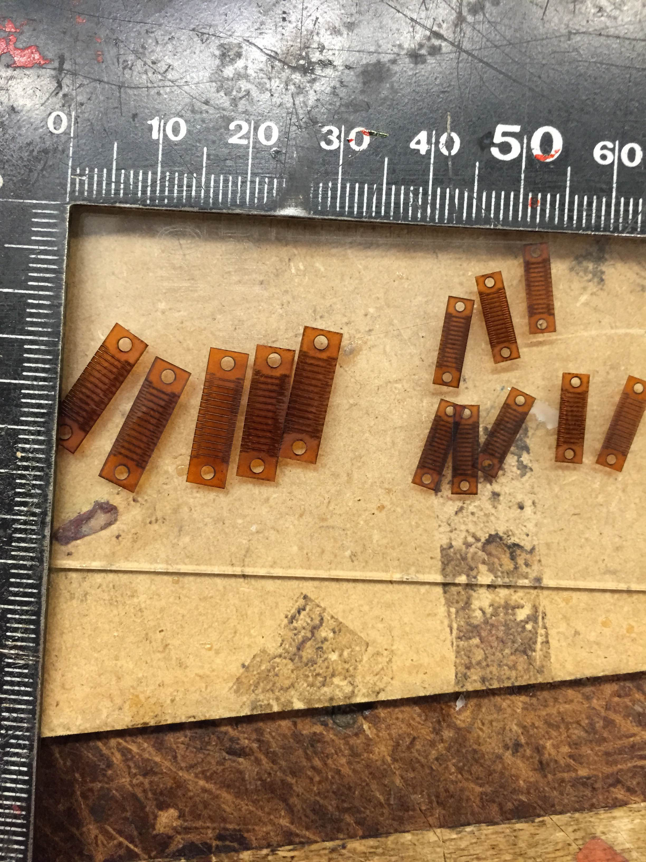
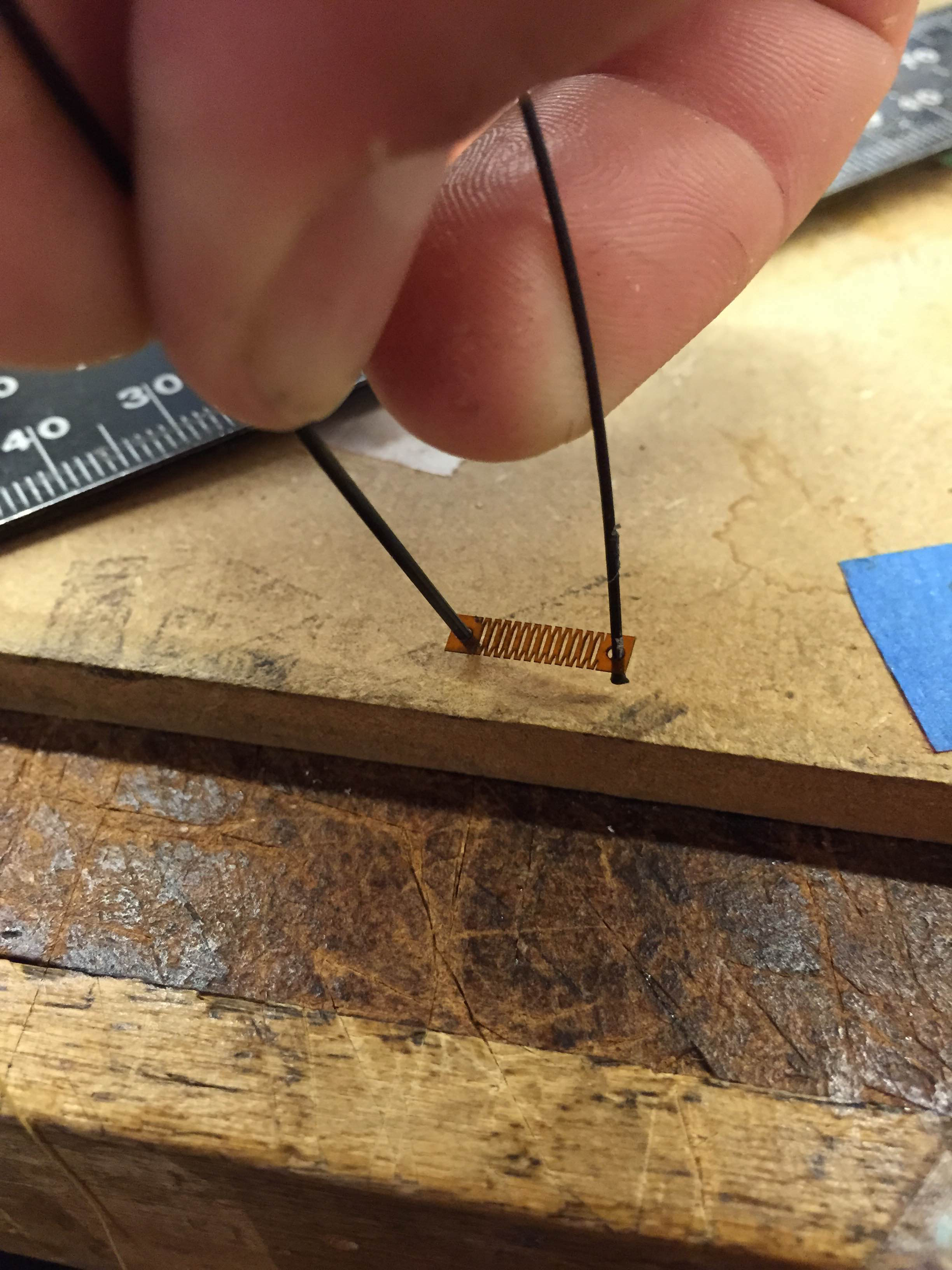
I then cut a second batch scaled up 150%. They were predictably very similar but a bit more durable.
Wednesday, July 8
This morning, I talked with Hao about different methods for improving foot performance. He suggested I create feet with multiple rows, which would both increase the number of hooks and prevent the "swinging" observed when there is only one hook in contact. I also observed some of the more intricate foot prototypes created using SDM, which allowed for combining rigid parts with an elastic material to create compliance in each individual foot. While the SDM prototypes are too heavy to be practical for Crazyflie, I hope to incorporate some of the ideas developed there into my lightweight foot prototypes.
To create multiple rows and also to have more fingers available, I decided to laser cut the kapton for my newest foot prototypes. After creating a quick Solidworks drawing, I went to the TLTL with Hao and cut out the pieces on the IR laser there. During the lunchtime perching meeting, Mark suggested I use the UV laser down the hall in the CHARM Lab, and pointed me towards Mark Cuson's work using that laser from last summer. I recut the foot pieces with the UV laser after lunch with Arul's help.
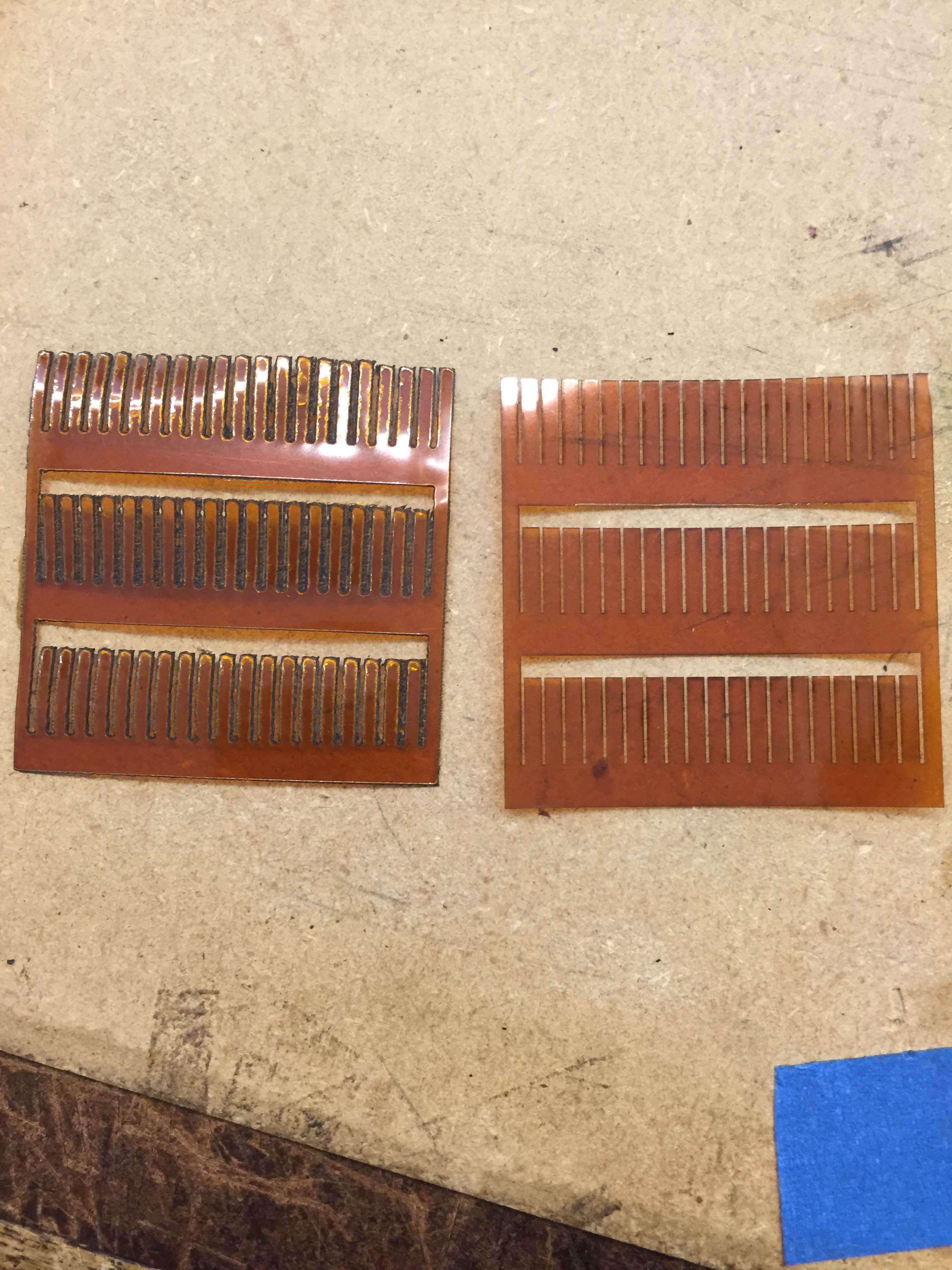
Kapton foot prototypes, cut with TLTL's IR laser on the left and CHARM's UV laser on the right. For scale, each is a 40mm x 40mm square, and each finger is about 1.66mm wide
I attempted to attach hooks to the kapton feet, but having stayed up pretty late Monday night, I struggled with the fine motor skills necessary to place the hooks onto such a small surface. I will try to revisit the feet tomorrow after getting some rest. I spent the end of the day reading Mark Cuson's summer blog from last summer, and also examined some of his remaining kapton foot prototypes. He had some very cool ideas that I will definitely incorporate into my foot prototypes.
Tuesday, July 7
Yesterday afternoon and this morning, I struggled with using the Bitcraze Virtual Machine for programming Crazyflie. There were some issues launching the Pycharm IDE for writing Python scripts, so after I ran out of ideas, I emailed Morgan and addressed some of the minor mechanical bugs on Crazyflie. I rebuilt the tail mechanism to be much more rigid and robust, and shaved off a tenth of a gram in the process. I also readjusted the tension in the tendons and gave the grippers a slightly shallower angle for easier perching. After Morgan responded to my email giving some direction, I was able to launch Pycharm and execute some of the pre-existing scripts. At this point, I determined the range of servo positions that were within the climbing mechanism's range of motion.
I then wrote a quick script that attempted to climb by just moving the servo back and forth for approximately a minute, and tested outside. The spiny feet were having a very difficult time gripping the wall, even though the tail pressed them to the surface. When the top feet were pressed in by hand, the servo also had a bit of a hard time pulling the robot's weight up, so I might use a shorter lever arm and less overall range of motion so that it will be able to climb if a clean grasp is accomplished. The robot also would often grab with one or two hooks at the edge of a foot, and then swing about that point.
My top priority moving forward will be creating feet that have a high success rate for gripping and resist curling over when slid in the anti-preferred direction. I will leave the current frame and mechanism intact in order to test different feet.
Monday, July 6
Today, I finished the mechanical part of the perching/climbing prototype. The final version looks similar to the prototype from last Thursday, but more sturdily constructed. The center of Mass is located almost perfectly in the center (as determined by balancing the Crazyflie on my finger) and weighs in at 38.19g, well shy of the total Crazyflie + payload limit of 43g. Initial tests placing it on the wall showed reasonable rates of perching success (for rough surface grippers) and climbing under its own power also looked reasonable. I will now experimentally find the servo control values that correspond to the fully extended and retracted states for the climbing mechanism, and then write a simple climbing script to test climbing (assuming a successful perch). I will then explore dynamically perching and climbing.
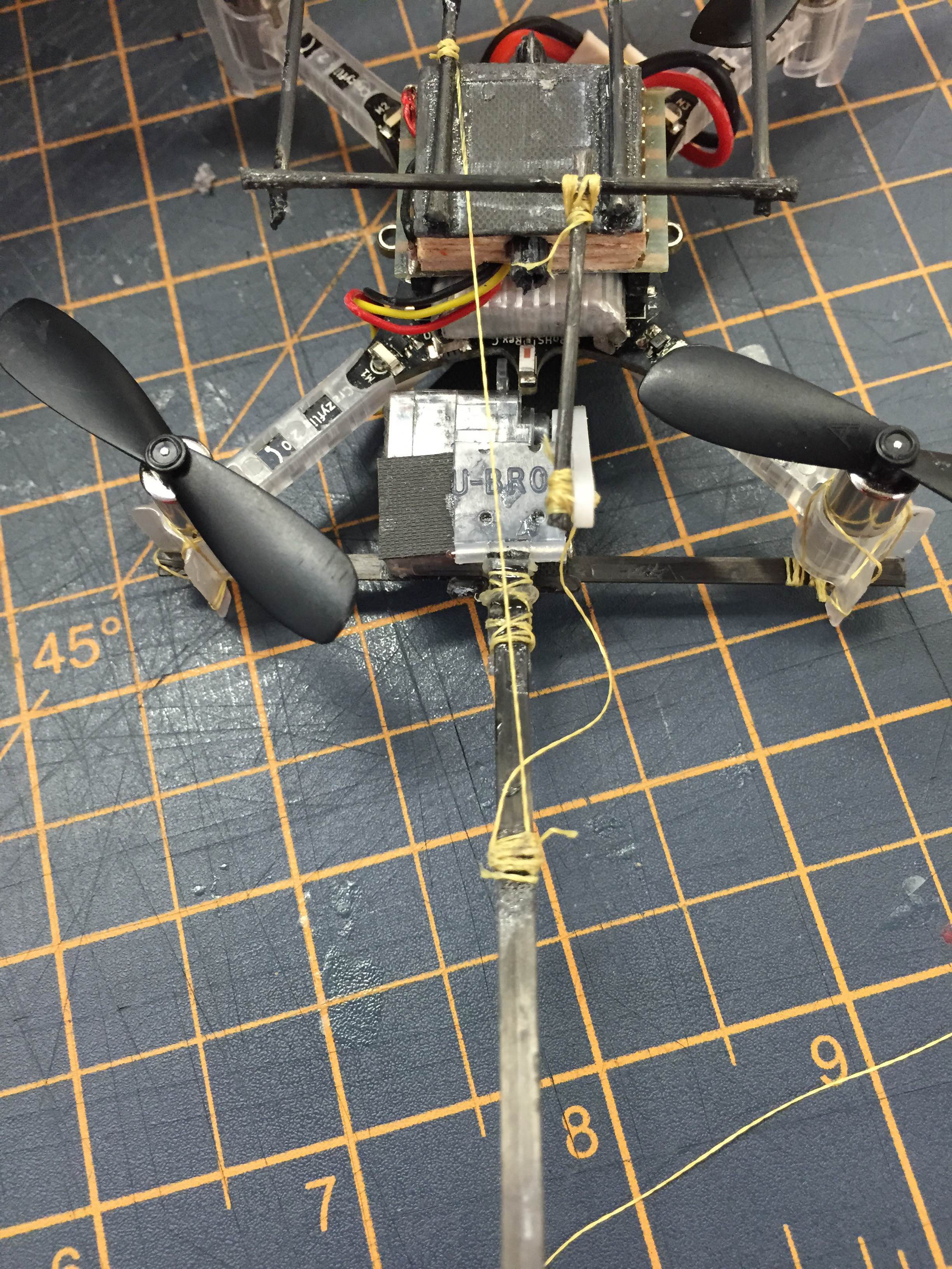
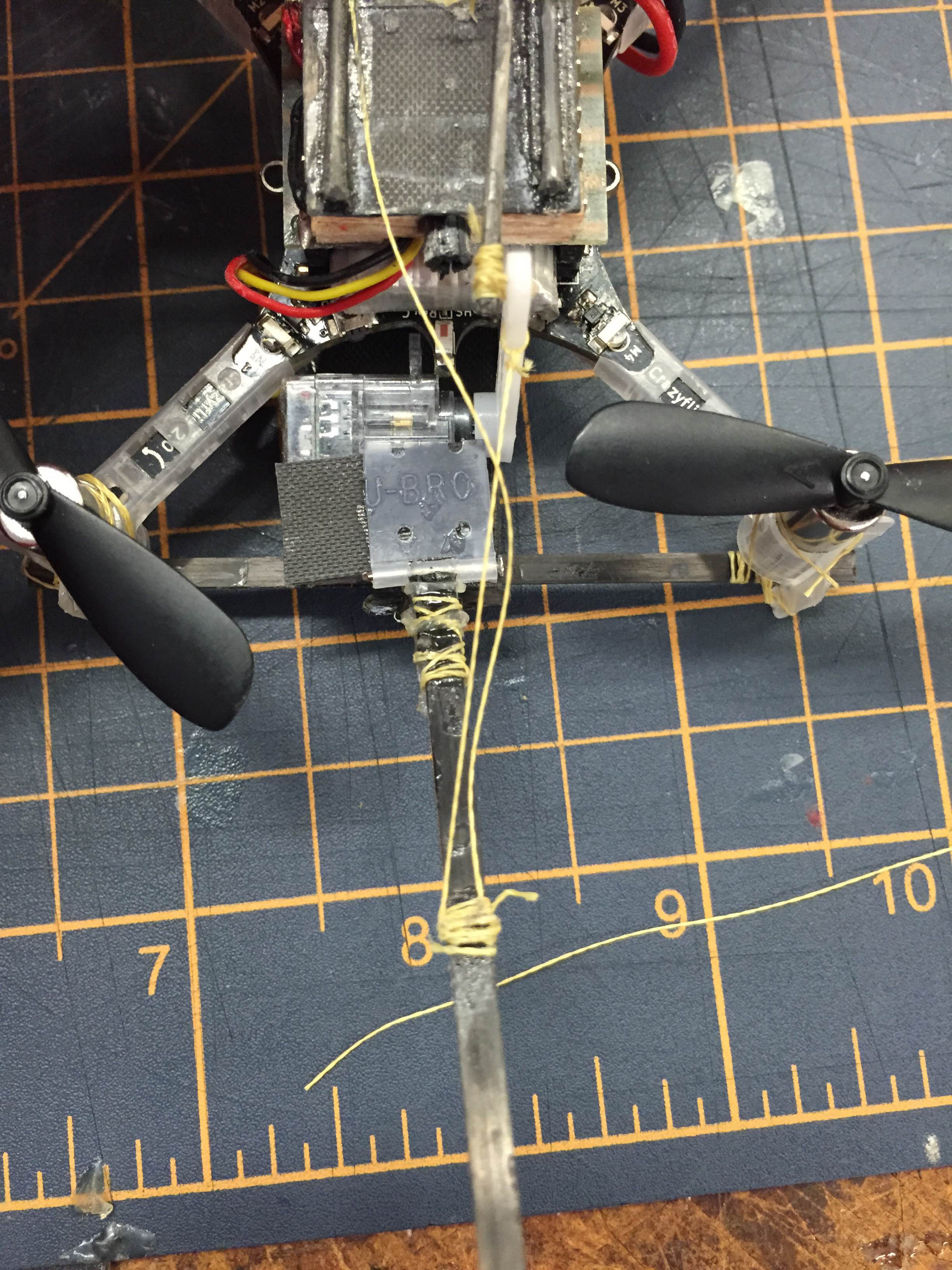
Left: 'Default' tendon to tail is engaged, holding it at it's resting height. Right: 'Transfer' tendon engaged, which presses the tail into the wall to activate the upper foot upon full extension.
Week 2
Thursday, July 2
I spent a long day at the lab today, from 9:45 till around 7:30. In the morning, I successfully designed a tail mechanism that would enable load transfer between feet. The feet featured a similar linear design to the previous iterations, but the tail was connected by a slack tendon that is tensioned when the upper foot is fully extended. This presses the upper foot into the wall, allowing its hooks to grasp the wall and assume the load.
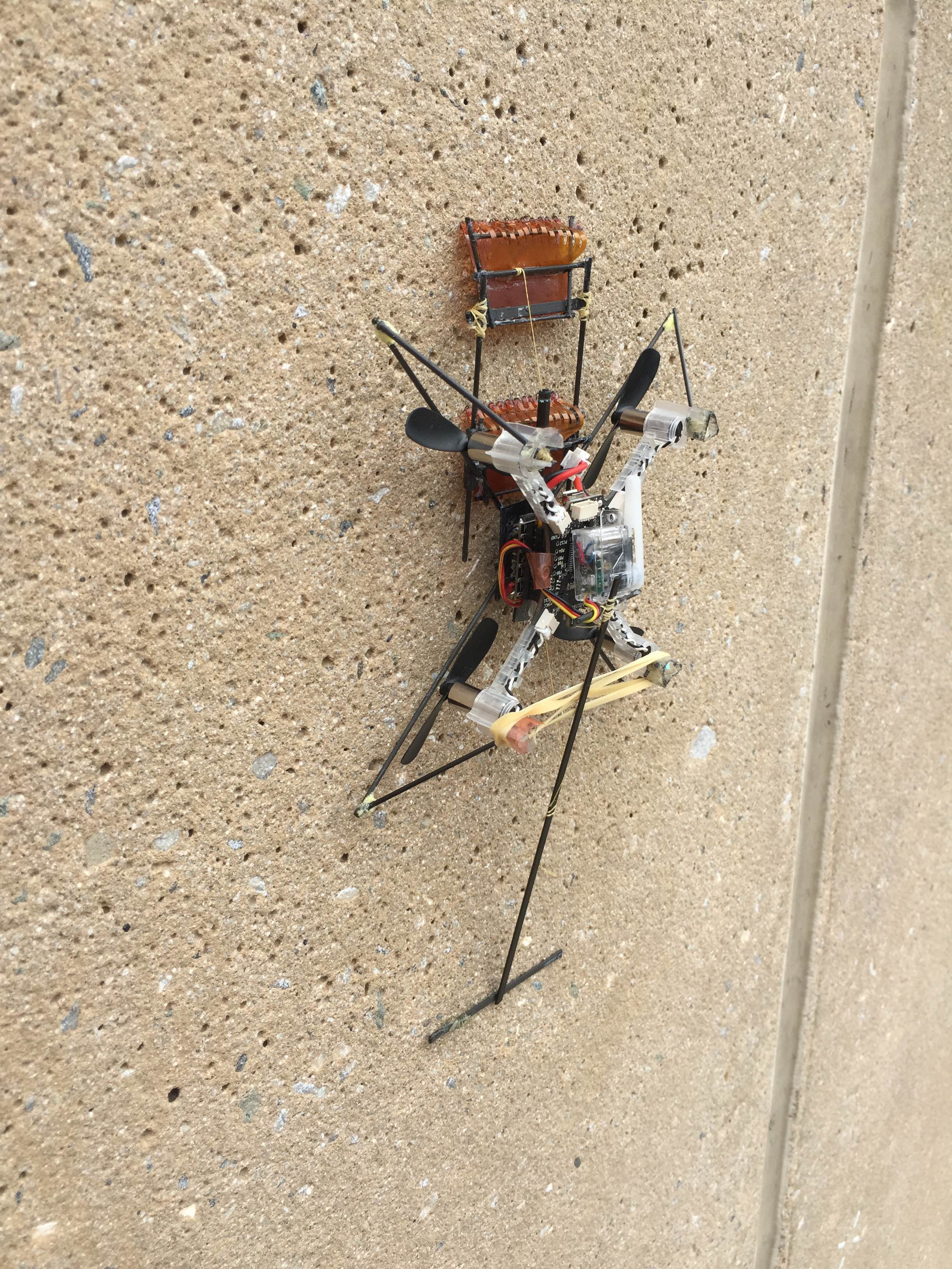
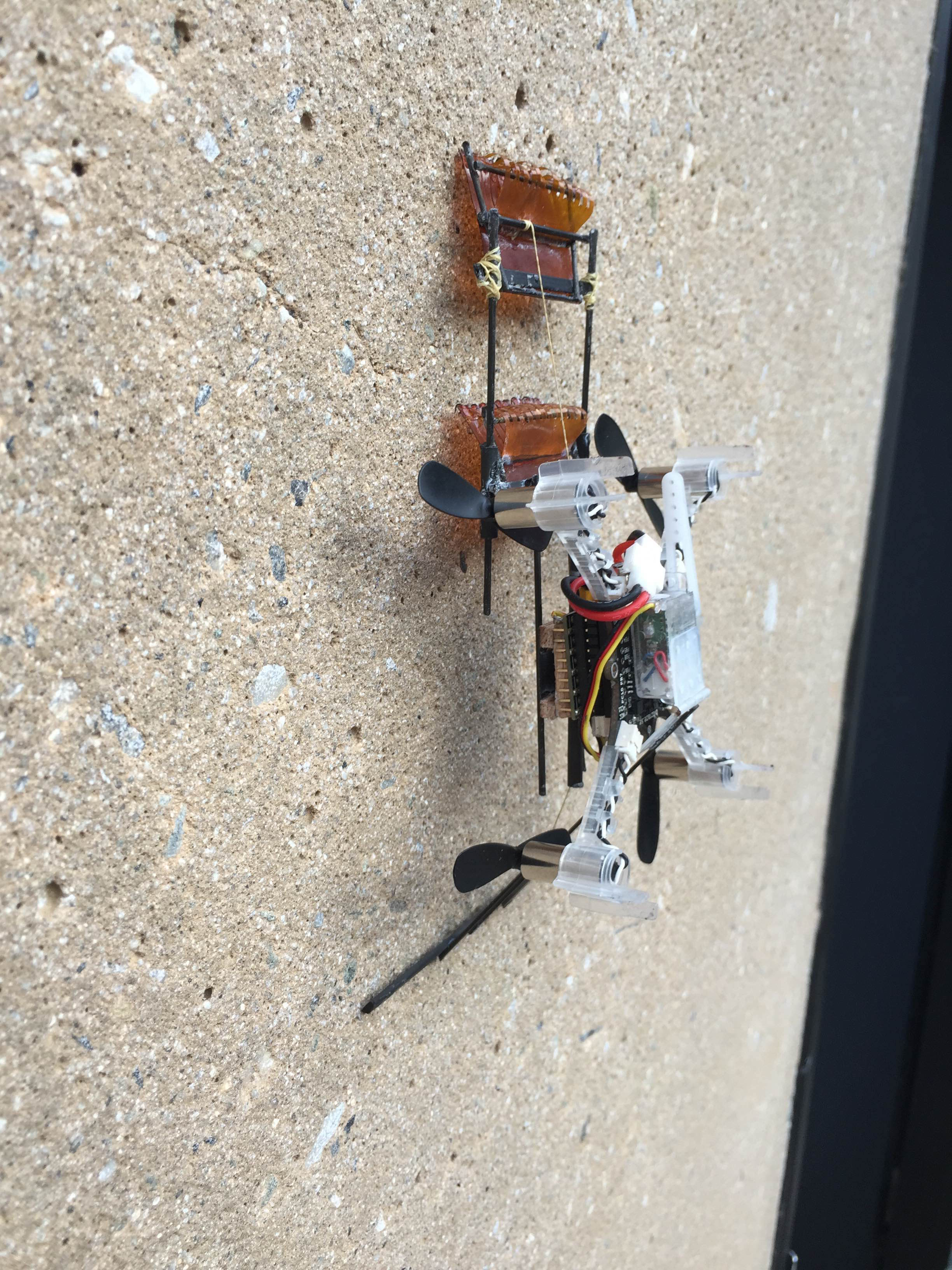
Left: Early, heavy prototype. Slack tendon can be seen attached from tail to top foot. Right: Lighter, afternoon prototype.
The prototype was messy and hastily built, as well as extremely heavy, so I spent the afternoon building a lighter, cleaner, and more secure version. This version features a fully functional tail and is significantly lighter than the prototype. I had almost finished this new version when I left this evening. I won't be in tomorrow, since the university is observing July 3 as the holiday we get off, so I have 4 only 4 work days left before Morgan returns (I'll be missing next Friday too). I will have to finish mechanically on Monday and work on writing a script the rest of the week.
Wednesday, July 1
Today, I prepared to continue work on the new climbing mechanism with a passive load transfer mechanism. I realized early in the day that re-using the existing microspine feet would not be possible for the new mechanism. In addition to being heavy and damaged from use, their geometry was not useful for adding passive load transfer, so I set out to create new feet. After talking with Hao about the feet he created for his microspine perching mechanism, I created lighter feet with kapton tendons behind them. Dealing with the tiny fishhooks was difficult, so this took me most of the morning. The final feet weighed 1.02g, so they're significantly lighter than the previous model (2.89g).
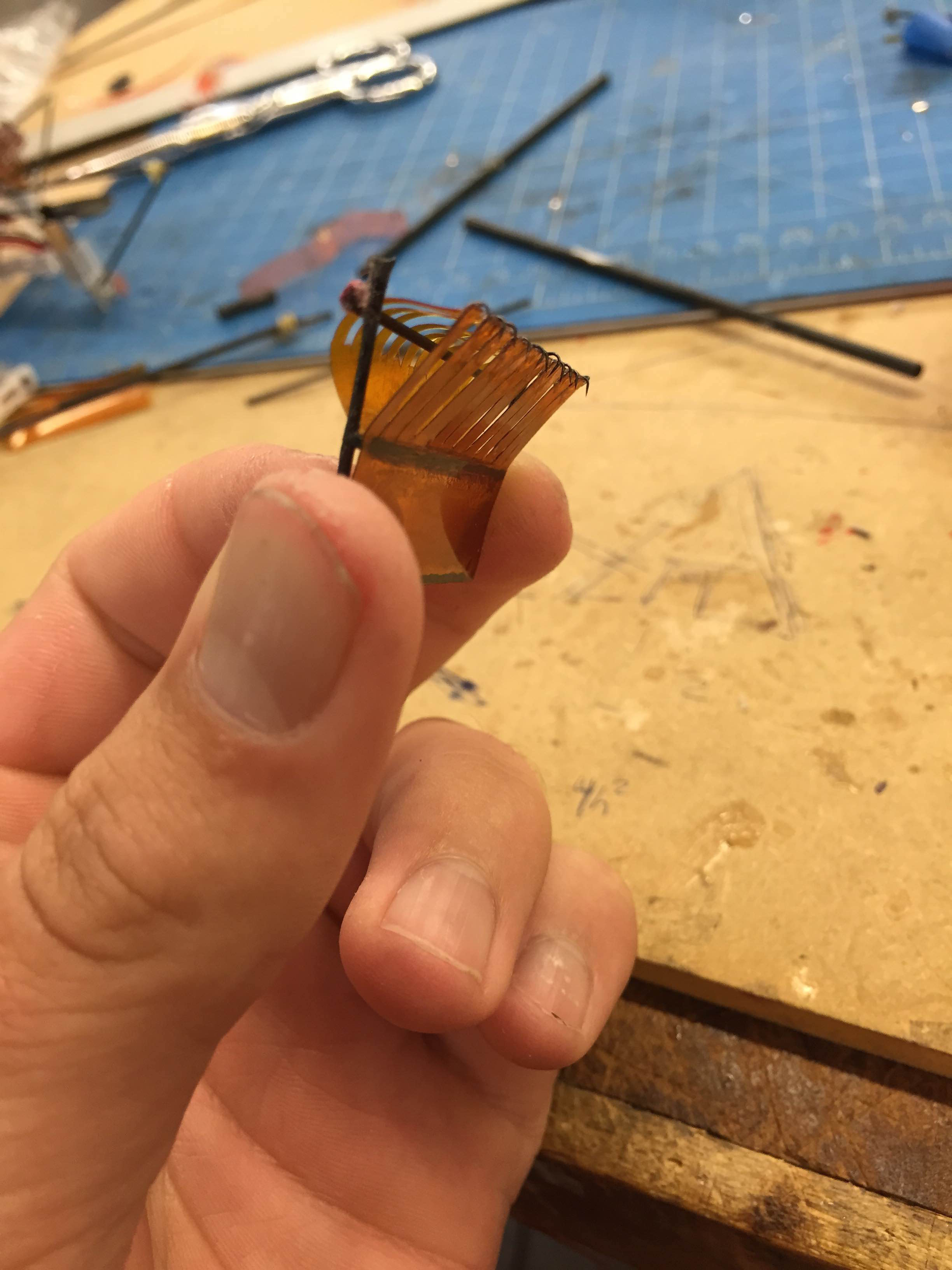
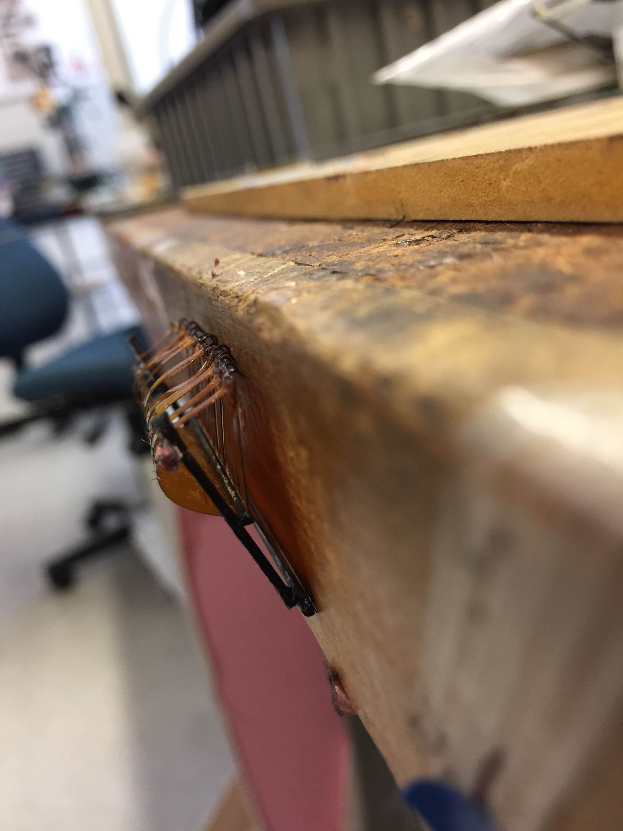
Left: New foot with kapton tendons and captain fingers. Right: New foot hanging on wood workbench, which is much smoother than the wall outside.
Compared to the kevlar thread tendons I was using before, the kapton tendons also create a spring-like forward force in compression in addition to holding tension well. This means that when pressed into the wall, each toe on the new feet is pressed forward into any grasping features that may exist. This should help with load transfer, since the toes will have a force pushing them into the wall as long as the feet are held close to the wall. To accomplish this, I will keep the feet close to each other while executing the inchworm gait and utilize a long carbon tail to counter the peeling moment.
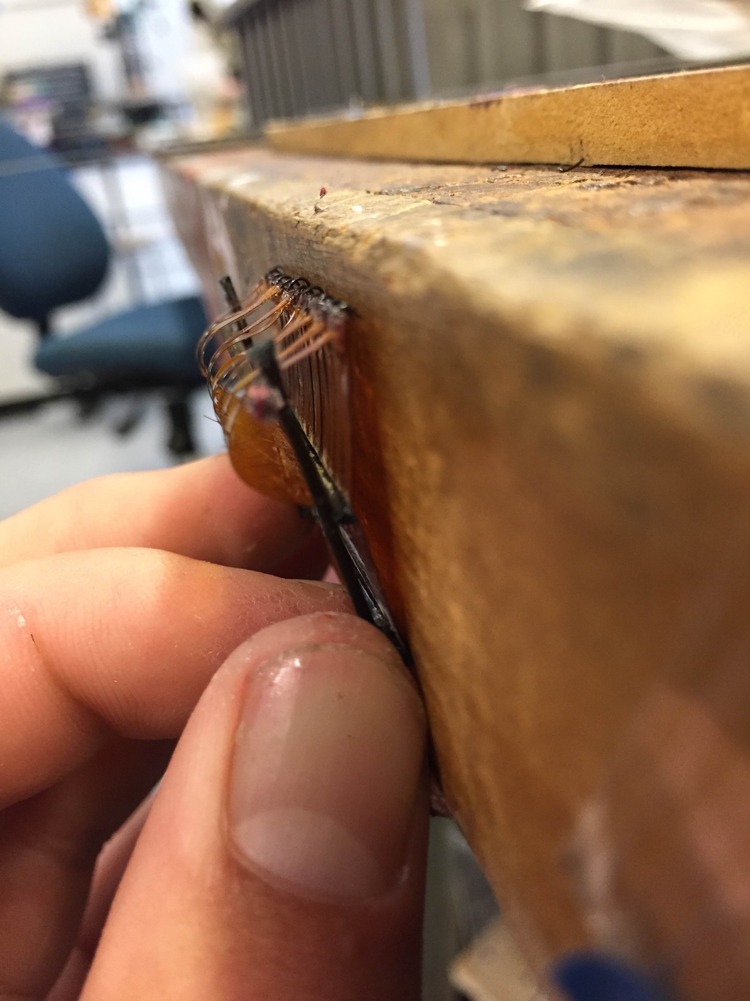
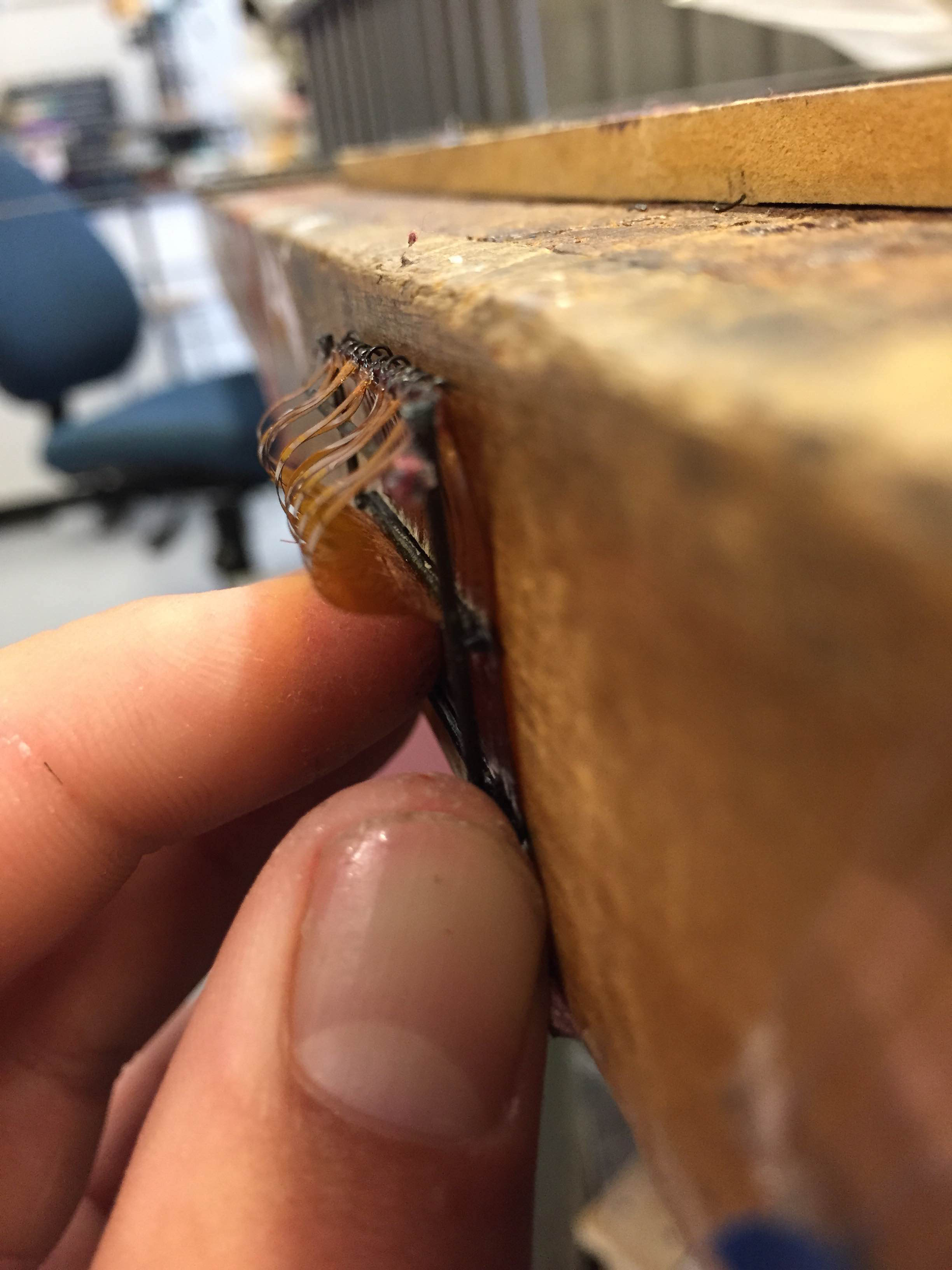
Left: Uncompressed foot in natural state, held gently against workbench. Right: Pressed into workbench, compressing the tendons.
At the end of the day, I experimented with adding different tails to Crazyflie to see how they affected perching with a single foot attached directly to the frame.
Tuesday, June 30
I spent today constructing and testing the latest prototype, which featured a very low gripper below the center of mass and a very high one actuated. Because of my problems with rotor space yesterday, I spent the morning creating a sturdy, minimally invasive frame on top of the Crazyflie that sat right above the rotor plane. This frame allowed for easy mounting of parts, and will be recycled for future iterations.
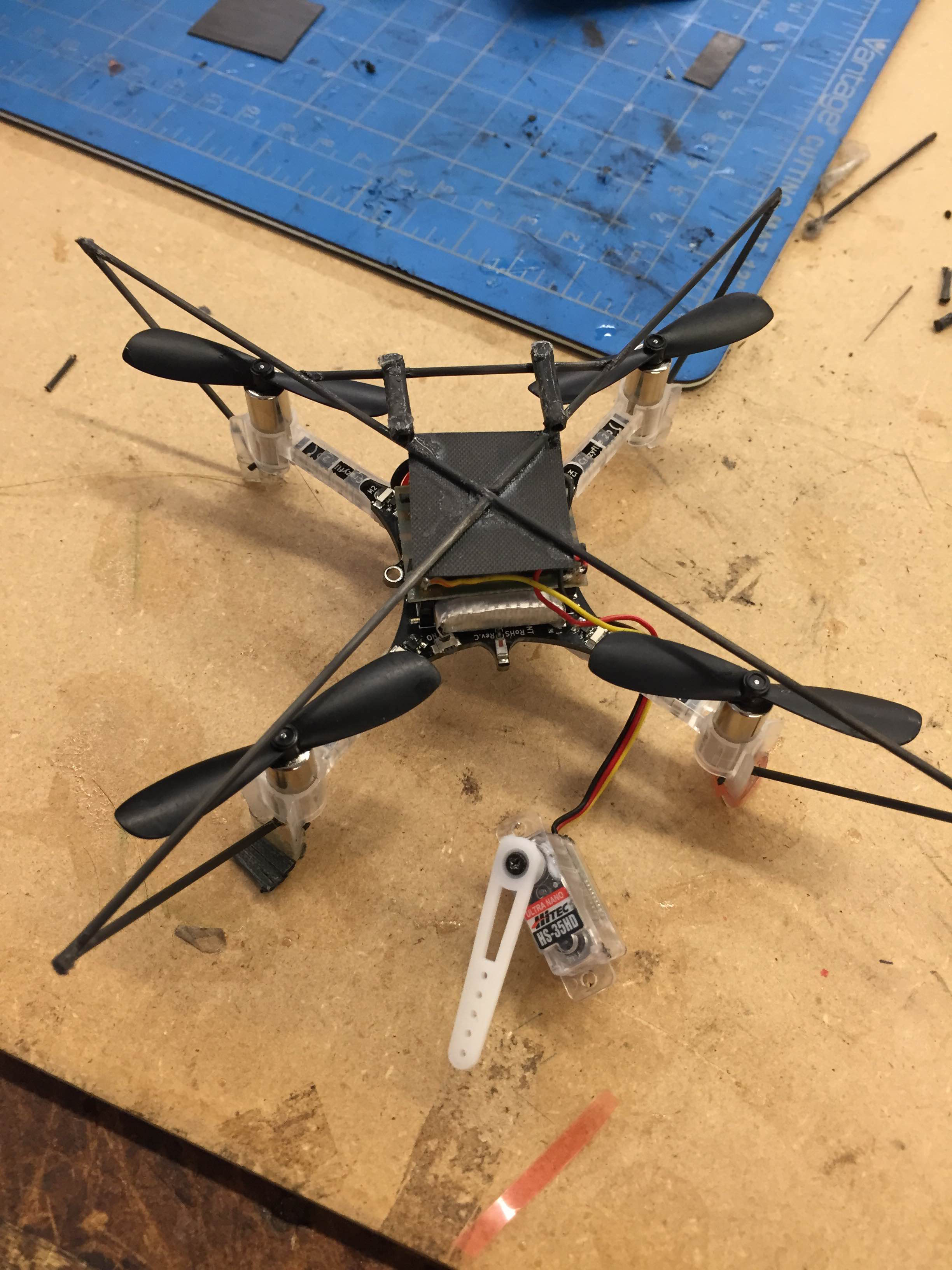
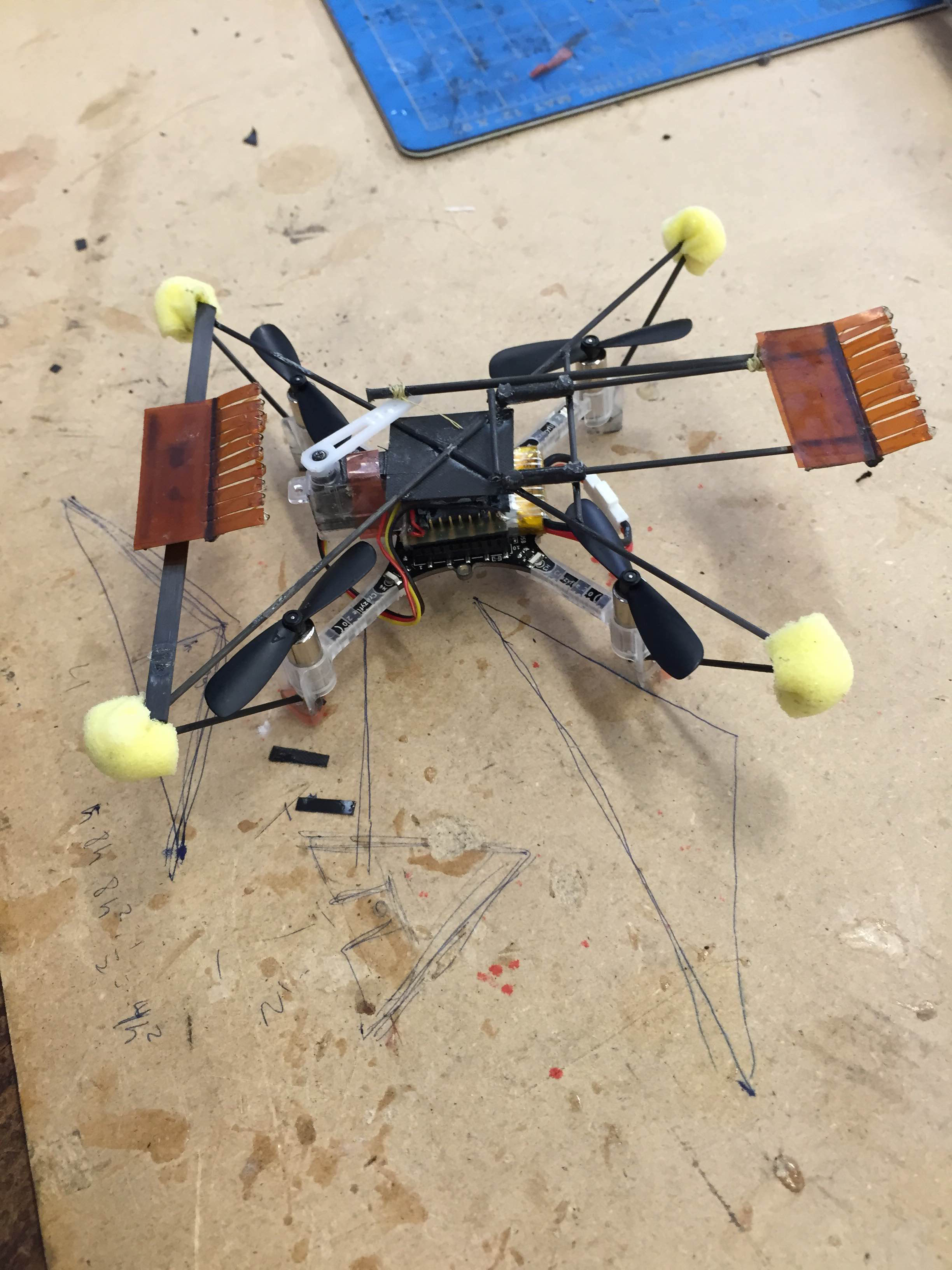
Today's iteration did not alleviate the issues of peeling I saw earlier. Despite a lower foot, the robot was still unable to activate the spines on the top hook. Near the end of the day, I talked with Elliot about his inchworm-gait climber that utilized the gecko adhesive, and he revealed that he used a small spring that caused each foot to "activate" when appropriate and suggested I try something similar, with a long tail. I also spoke with Matt about the transfer of gripper between feet, and he said that using a passive mechanism such as a ramp to press the foot into the wall for activation would probably work. This will probably require a much smaller gait, but would allow for a more reliable perch in addition to climbing.
Monday, June 29
I continued work on the Crazyflie climbing prototype, and ran into a lot of connected issues regarding the robot's weight distribution. The second prototype i started on Thursday proved to be too large and unwieldy, and the top gripper would not grasp as the moment from the Crazyflie's weight pulled it away from the wall. The additions were also approaching the maximum 15g payload, and the center of mass was no longer centered, which would prevent Crazyflie from sustaining flight. I set out to build a more compact version without these mass issues
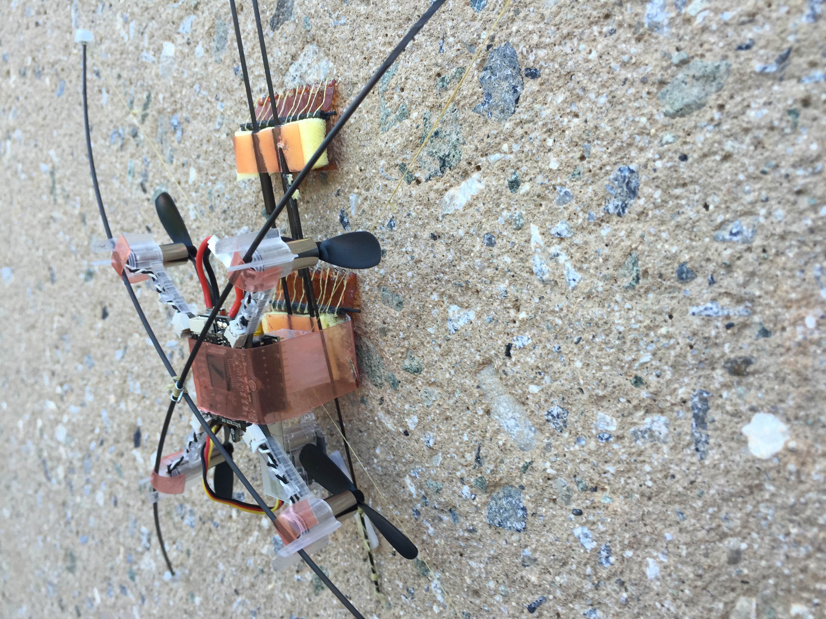
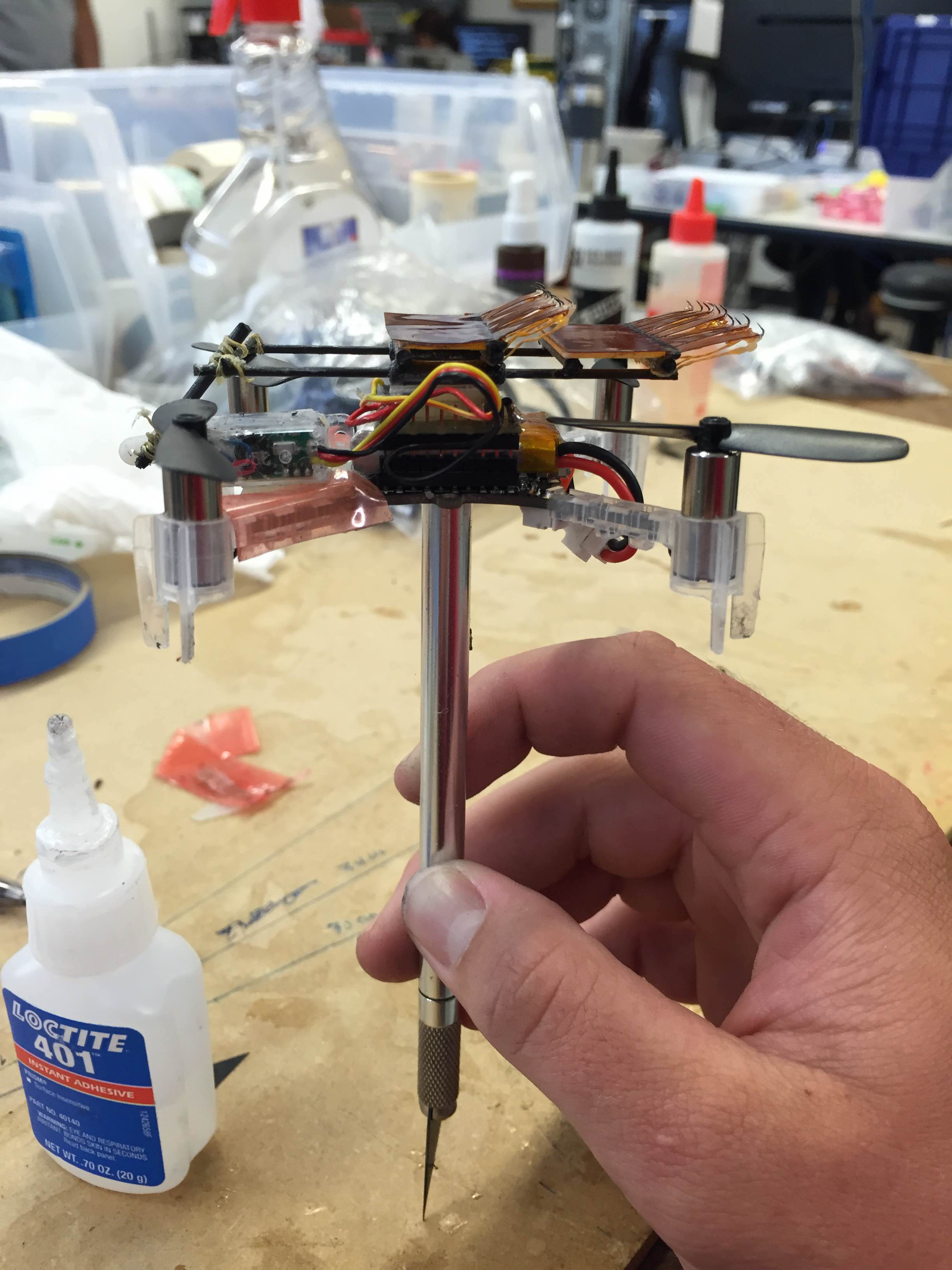
Left: Mk. II prototype with outriggers on wall. Right: More compact Mk. III showing improved center of mass location
The more compact design featured a shorter gait length and used the servo arm as a tail to press the upper foot into the wall, as shown in the pictures below. This prototype had good mass distribution and was significantly lighter than the Mk. II. The grippers were also located closer to the robot's center of mass, so the center of mass would be closer to the wall to create a reduced peeling moment.
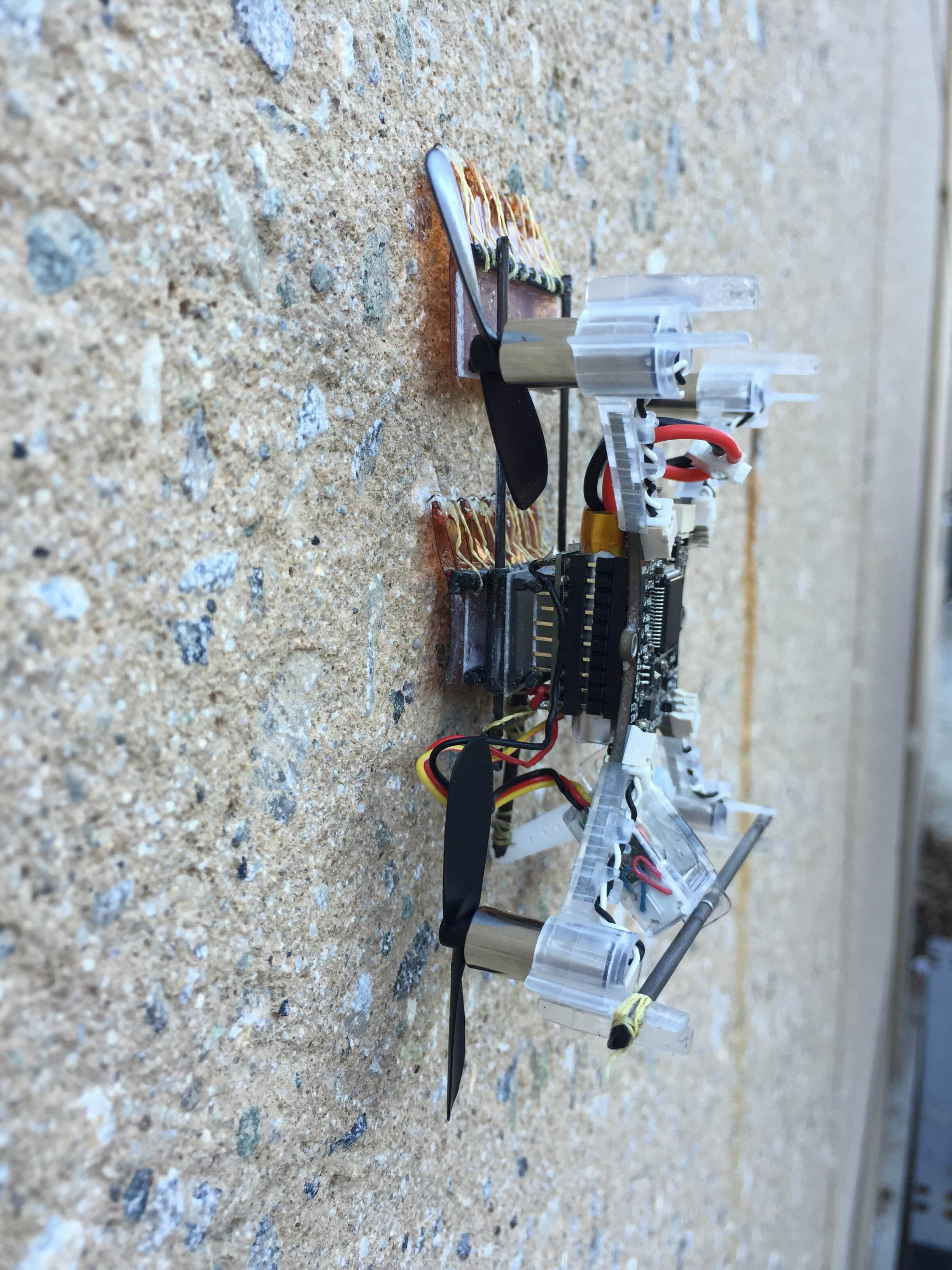
Left: Mk. III on the wall. Right: Servo arm used as a 'tail' to press the upper gripper into the wall to grasp.
Moving the grasping mechanisms closer to the center of mass caused everything to be uncomfortably close to the rotors, and introduced the need for a tail that would press the grippers into the wall. All of my tail prototypes were not robust at all, so I will be changing the climber design yet again tomorrow. I plan on experimenting with placing the lower foot below the center of mass to eliminate the need for a tail.
Week 1
Friday, June 26
Today was lab retreat. We went to Pomponio State Beach and bonded by playing some touch football, cooking burgers, and talking about our summer goals. I started the day playing some 5-on-5 touch football with Arul, Isabel, Ian, Hao, and some others. I also got to spend some time cooking, which I always enjoy. Talking about our goals for the summer was also really cool. I walked away with a much clearer picture of my direction for the summer, as well as orienting myself to everyone else's roles in the lab. At the end of the day, I ran into the ocean with Elliot. It was very cold, but very fun. Overall, it was a very fun day and I got to know my colleagues in the lab a lot better.
Thursday, June 25
Today was lab cleaning, so I spent the morning organizing one of the lab's central workbenches and the stockpile of materials (acrylic, fiberglass, foam etc) underneath it. Although it took until lunch to complete, it was nice in the afternoon to have a clean space, since Morgan and I could both work at the bench, which would have been impossible before.
In the afternoon, I began modifying the climbing mechanism. After looking at a spine-based gripper Hao had made, I attached kevlar tendons to the backs of the kapton '"fingers" and added a foam layer between the gripper and chassis to create some compliance. The improvements allowed the mechanism to climb much more smoothly in additional small scale tests.
Gripping claw with yellow 'tendons' to prevent finger jamming and foam base to increase compliance. Left pad was similarly modified afterwards
I finished the day by helping the other SURI students plan our lab retreat (which is tomorrow) and preparing to mount the climbing mechanism to Crazyflie. Since this will be Morgan's last day for the next two weeks, we talked about the direction of the project, which I will carry on while he is out.
Wednesday, June 24
In the morning, I worked on a prototype of an anchor for Morgan's Kitebot project. I spent a significant amount of time on the drawing board, and built a fairly functional proof-of-concept prototype. When we dragged it through some trees outside, it hooked on them fairly well, but still snagged after the hook was manually released. It will need to be smoothed out and possibly redesigned so that the release mechanism works with less force.
The hook mechanism for Kitebot
At noon, I attended the perching meeting with Morgan, Matt, Hao, and Mark. We discussed the progress made yesterday with Crazyflie taking off and how it impacted the direction of the rest of summer. Morgan will be gone for two weeks starting Friday, so I will be working on the perch and climb mechanism and code during his absence. Since this will require the microspine mechanism, Hao will help me with some mechanism design problems and help me debug any issues I face. I spent the second half of the day prototyping climbing mechanisms for Crazyflie.
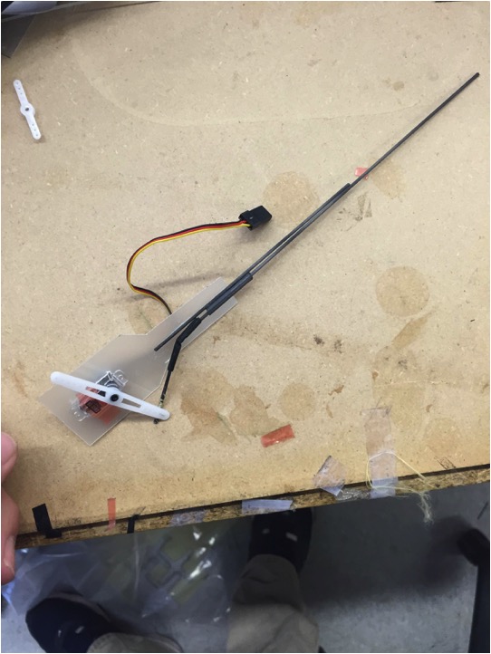
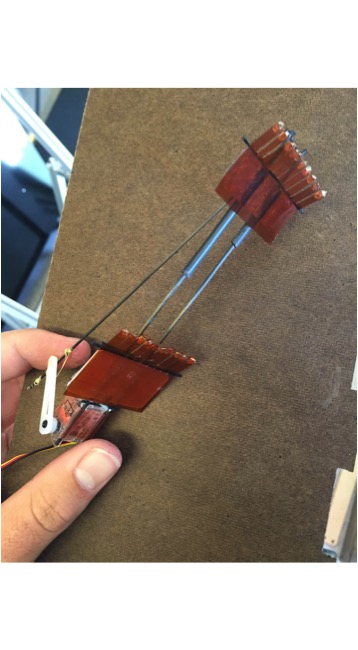
Left: Original prototype linkage, weighing ~8 grams before adding feet. Right: Second prototype with more robust linear sliding motion and weighing 8.6 g total (with feet).
The two prototypes both successfully climbed outside in small-scale, unloaded testing. Some jamming of the spines occurred for both (though less pronounced on the second prototype) so I will probably talk to Hao about how to prevent this.
Tuesday, June 23
When I arrived this morning, I helped Morgan look through the Crazyflie firmware and some open-source code posted on the Crazyflie forum. Someone had set up PWM-output from the Crazyflie designed to play music over a small buzzer, and we wished to adapt this code to drive a small PWM servo. After looking through the source code together for about an hour and looking at pin outputs on the oscilloscope, Morgan and I figured out how to command the frequency and pulse width and established an appropriate range for operating the small servo. I then soldered the servo to the output pins on the battery holder that mounts on top of the Crazyflie's board. We tested and recorded how different pulse widths corresponded to different servo positions.
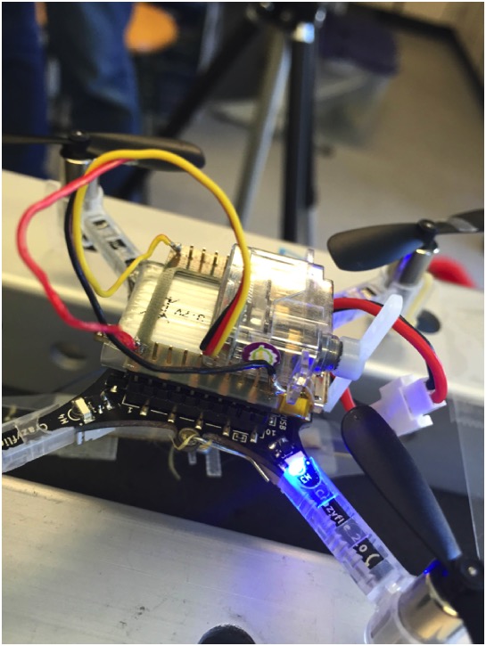
After lunch, Morgan worked on creating the takeoff mechanism while I searched through Crazyflie documentation online to figure out how to activate the servo using the Python API (we were previously just doing this in the GUI). We then then modified the perching script to account for the new mass and inertia of the copter. After debugging the servo activation, we were able to successfully take off from a perched position.
Currently, the latching mechanism uses the servo to "peel back" the top gecko adhesive pad, so this peeling propagates until the Crazyflie falls off and rights itself in flight.
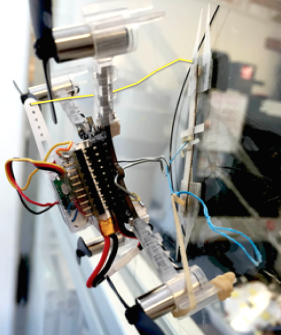
The yellow, slack string connects the servo to the top pad
Monday, June 22
Today I attended the SURI kickoff breakfast and got set up on the BDML Wiki. I also completed STARS Lab safety training. Since Mark is at MIT today and tomorrow, I talked with some of the grad students regarding potential projects. I found Hao's work on the space gripper very interesting, as it'll provide a great way for me to refine my CAD/rapid prototyping skills. I spent the latter part of the day reading some of the BDML papers to better understand some of the things I will be working with.