new web: http://bdml.stanford.edu/pmwiki
TWiki > RisePrivate Web>PrivateRiSE > PerchingBird>PerchingAutopilot (22 Sep 2008, AlexisLD)
Paparazzi Board
We currently have the Paparazzi Classix Board. This board has the code to do autonomous flight (takeoff, climb, cruise, landing) with GPS and IR sensors. We supplemented it with a few sensors for hovering:- 5 axis IMU (2 gyros at 500 deg/s, 3 Accelerometers at 3g, 2 grams). This board is based on the ADXL330 and IDG300.
- 2 axis Gyro (2 gyros at 500 deg/s, about 2 grams)
- Devantech SRF02 Ultrasonic Sensor (0.15 to 6 m, 65ms update rate, I2C? protocol, 5 grams)
- I2C Protocol details for the SRF02 which has a similar protocol to the SRF08 (look for srf08.c in the paparazzi library)
- Doesn't really work for a range of more than 2m (lot of failures to detect).
- The SRF02 is a 5V sensor, but the I2C? is 3.3V compatible.
Programming the bootloader
- Plug the serial connector
- Power the Classix while connection P0.14 to ground to tell the chip to be in bootloader download mode
- Type
make upload_bl PROC=GENERIC(USB programming determined by pin P0.23) download the bootloader. The FBW chip was originally programmed withPROC=APso the USB download is determined from pin P0.03, also used by the I2C? bus). This can't be changed anymore as the FBW chip serial port is broken!!
Downloading the code with USB
- FBW Remove the I2C? jumper before programming with the Paparazzi GUI
- AP Just connect the USB wire and program it using the Paparazzi GUI!
Sensors Integration
The sensors added to the paparazzi system provide:- Pitch and yaw from gravity measurement (accelerometer)
- Pitch, yaw and roll angular velocity from the gyro
- Altitude with the SRF02 (bad sensor, maximum distance of about 120cm)
Complementary filters
None of those measurement are perfect: rate gyro have a tendency to drift while gravity reading by the accelerometer must be done at rest to get accurate results. We can get around that by using the accelerometer at low frequency and the gyro at high frequency, combining the measurement in what we call a complementary filter. The first order form for this filter is: The problem with this kind of filter is that if the calibration of the zero reading on the gyro is not perfect then we get a steady state error on the output of the filter. To solve that, a second order complementary filter of this form can be used:
 This filter is not sensitive to the zero calibration of the gyro. By using \tau = 1 rad/sec, and sampling at 60Hz we get these discrete filters for rate gyro and gravity readings :
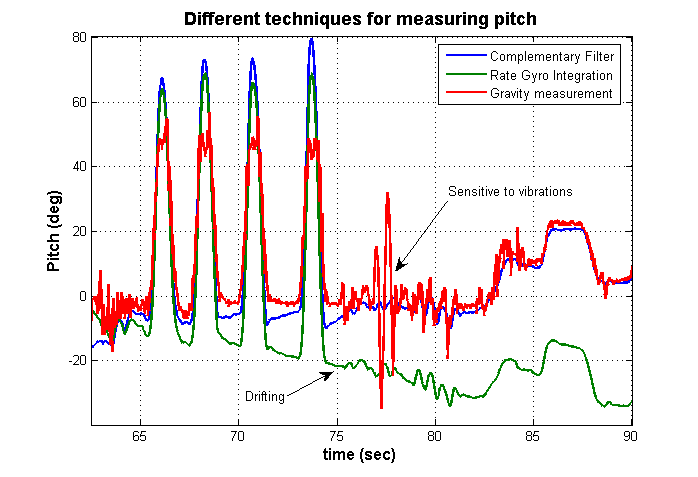
 These filters provide an efficient way to accurately measure yaw and pitch at all frequencies, is robust to vibrations (usually interpreted as a angle change by the accelerometer) and exhibit no drift. The following figure show the comparison of pitch measurement from gravity measurement with the accelerometer, from integrated signal from the rate gyro and with the complementary filter:
 Both pitch and yaw are using the same complementary filter.
Controller
This section explains the different controller for each axis on the plane.Pitch and Yaw
Both pitch and yaw controller are using the same kind of controller. The controller was first designed using the Ziegler-Nichols method, then transformed in a lead filter that looks like 2000*(s+5.3)/(s+26.5). The angle measurement are also low pass filtered at 15Hz. All that is integrated in the following discrete equation (60Hz): The controller uses as setpoint the input from the RC controller.
Roll
The roll controller consist of only a proportional controller around the gyro measurement. It damps the roll motion so that it doesn't move too much. The signal from the gyro is also low pass filtered at 2Hz, resulting in this discrete equation:
Altitude
The altitude controller is a little bit more tricky! A "floating mass" like a plane would usually consist of two poles at the origin, but:- Low update rate (10Hz) of the range sensor makes the system more unstable.
- Low actuator (motor-propeller) dynamics add a third pole to the system.
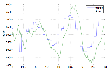
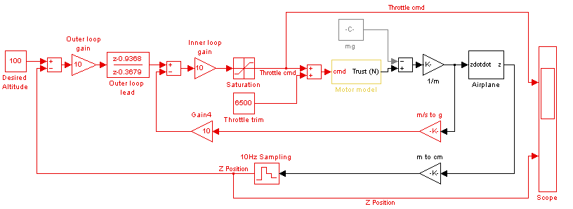 In this model, the motor is represented as a first order system of the form 12.57/(s+12.57). This model was inspired from the delay of 0.25 sec observed between the throttle command and the measured acceleration, as shown on the following figure:
Hovering videos
-- AlexisLD - 06 Aug 2007Ideas, requests, problems regarding TWiki? Send feedback