new web: http://bdml.stanford.edu/pmwiki
TWiki > RisePrivate Web>LandingExperiments (01 Jul 2010, AlexisLD)
Finding the optimal landing point
Problem Description
Now that we have a valid landing simulator to simulate the forces/motion during landing, and that we used it to compute the theoretical landing envelope, we want to validate that envelope. We could validate each point in it, but because the landing envelope is a 4 dimensions state space, even a rough discretization would require a huge number of point to test (10 points for each states = 10^4 experiments). So the question is how can we validate the landing envelope without testing all those points?Optimize the process by using some Design of Experiment (DOE) techniques
The idea here is to use DOE techniques to minimize the number of test required to find the optimal landing point (for reference see http://www.itl.nist.gov/div898/handbook/pri/section5/pri53.htm). The general strategy is to pick up the minimum number of point that will allow us to determine the main parameters of a certain model. In our case, where we have 4 states, two options are mostly interesting:- Estimate a linear model by using a 2^(4-1) (resolution IV) fractional factorial design. This consist of a minimum of 8 experiments used to determine the main effects of a linear model. The resolution IV means that the main effects are confounded with, at worst, three-factor interactions.
- Estimate a quadratic model by using a Box-Behnken_design, also called response surface design. This required 27 experimental data points.
- LECTURE_6.ppt: Intro to orthogonal arrays
- Introduction To Taguchi Method
- Useful function in matlab: anova1, anova2, anovan, polyval, regstats, rstool, etc.
- Matlab tutorial: Improving an Engine Cooling Fan Using Design for Six Sigma Techniques
Simulation using a 2^(4-1) (resolution IV) fractional factorial design (8 experiments)
Unfortunately, the fit to the linear model estimated using this procedure is really bad. It might work for really small regions, but we might have challenges achieving that much accuracy and would probably required a few linear models (few sets of 8 experiments) to perform the full optimization.Simulation using a Box-Behnken design (27 experiments)
Running a Box-Behnken experimental design in simulation (27 experiments where we the states varies as follow: vx = 1.5 to 2m/s, vy = -0.4 to -0.9m/s, pitch = 65 to 85deg, angular velocity = 0 to -50deg/s) and trying to fit a quadratic model to it, we obtain a relatively good results (R^2 = 0.9696). Note that it is important to remain in the landing envelope (i.e. no rebound) otherwise the experimental point won't produce a meaningful Fn/Fs ratio. It is interesting to look take a look at the coefficients of the quadratic equation: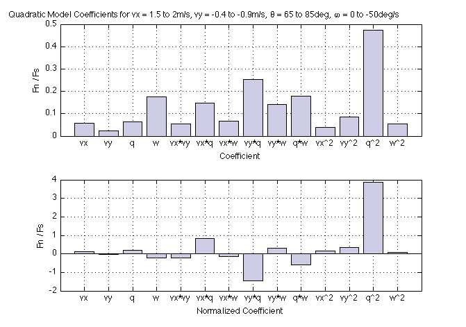 Unfortunately, all terms seems to be important in this model, and it would be hard to drop some terms (to reduce the number of experiments required). Using a DEX plot, we can estimate the optimal landing configuration for a certain horizontal velocity (vx) that will be determined by the airplane dynamics.
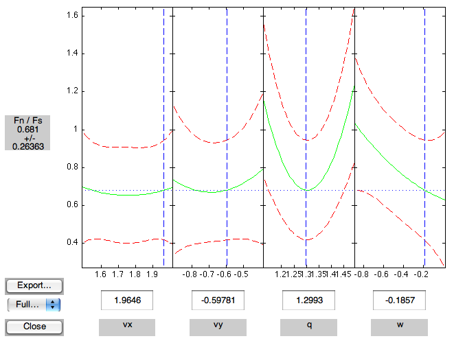 In the case illustrated on the figure above (vx = 1.96m/s, vy = -0.59m/s, qA = 1.299 rad, pitchrate = -.1857 rad/s), the predicted Fn/Fs ratio is 0.681 +/- 0.26. The Fn/Fs ratio from the simulator is 0.7241.
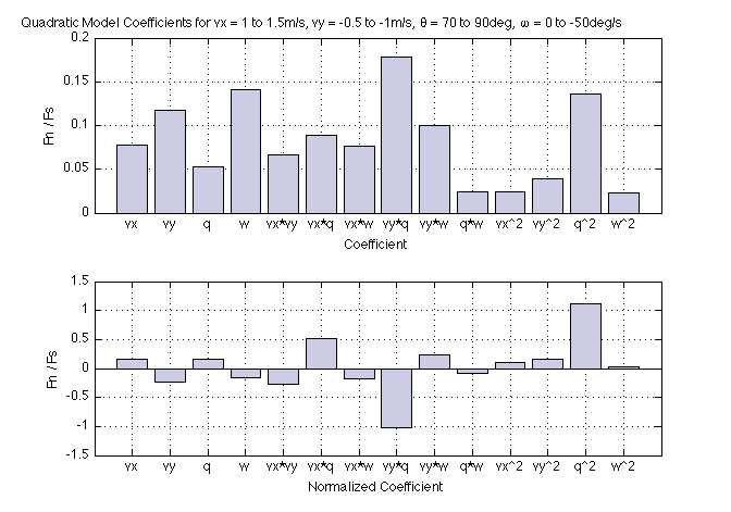
And here is another case for vx = 1 to 1.5m/s, vy = -0.5 to -1m/s, pitch = 70 to 90deg, angular velocity = 0 to -50deg/s. The R^2 value is 0.9151.
In the case illustrated on the figure above (vx = 1.96m/s, vy = -0.59m/s, qA = 1.299 rad, pitchrate = -.1857 rad/s), the predicted Fn/Fs ratio is 0.681 +/- 0.26. The Fn/Fs ratio from the simulator is 0.7241.
And here is another case for vx = 1 to 1.5m/s, vy = -0.5 to -1m/s, pitch = 70 to 90deg, angular velocity = 0 to -50deg/s. The R^2 value is 0.9151.
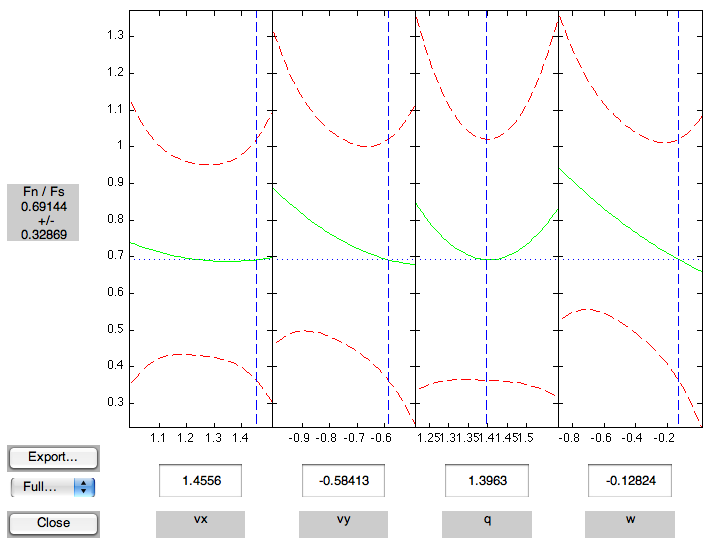 The predicted value 0.69144 matches relatively well with the simulator (0.7119).
Looking at this, it seems that there will be a few challenges to face with using this technique on a real system:
The predicted value 0.69144 matches relatively well with the simulator (0.7119).
Looking at this, it seems that there will be a few challenges to face with using this technique on a real system: - We need 27 successful landings... cause the Fn/Fs ratio is meaningless when the landing is unsuccessful. That means that some regions (boundaries) of the landing envelope will be quite hard to explore... To ease the problem we could use carpet (which sustains ratio of Fn/Fs > 1).
- Hopefully the Fn/Fs ratio observed during a real experiment are not too noisy and reproducible, as the observed ratio in the simulation are between 0.7 and 1.2.
- It is an interesting way to optimize a process and create an experimental response surface.
- Could we use another metric to quantify the landings? Success rate would be good, but hard to implement with only a few experiments
Landing experiments (reverse chronological order):
- Landing with Dummy on 2008-08-01, leg-like landing gear:
- 2008-08-01_Perching_BirdSuspension_small.mov
- Adjustable friction damping at both the ankle and knee joint.
- Work really well as long as the plane is "falling down" (from as high as 20cm in the video) so that it loads the spines.
- Fails when coming too fast toward the wall (horizontal or upward trajectory), then rebound without the spine having a chance to grab the wall. Maybe stiffer horizontal suspension?
- Seems that part of the problem when coming too fast toward the wall is that when the suspension is fully compressed, the spines are not touching the wall. This is now fixed!
- 2008-08-01_Perching_BirdSuspension_small.mov
- Landing with Dummy on 2008-07-02, Taildragger landing gear:
- 2008-07-02_PerchingWithDummyFCsmall.mov
- Ankles too soft and not enough damped
- Metal spring of the landing gear not enough damp as it unloads the spines on the rebound if the plane is dropping too fast parallel to the wall.
- The suspension has been model as a spring-mass-damper system with m = 320g, k = 110 N/m, zeta = 0.1 and thus b = 1.18 Ns/m (about 5 oscillations in 1.9sec before being negligible)...
- According to that model, a maximum downward velocity of 0.75 m/s is allow before completely unloading the spines.
- 2008-07-02_PerchingWithDummyFCsmall.mov
- 2006/12/23 - Experiments run at Sherbrooke with spiny feet: BirdFeetAtSherby.mov
- The first test were done with a long tail so that as long as the propeller are running the aircraft "stick" on the wall...
- The tail was cut to allow take-off from the wall (could also be servo actuated to land with a long tail and allow take off)
- Long (left) and short (right) tail designs:
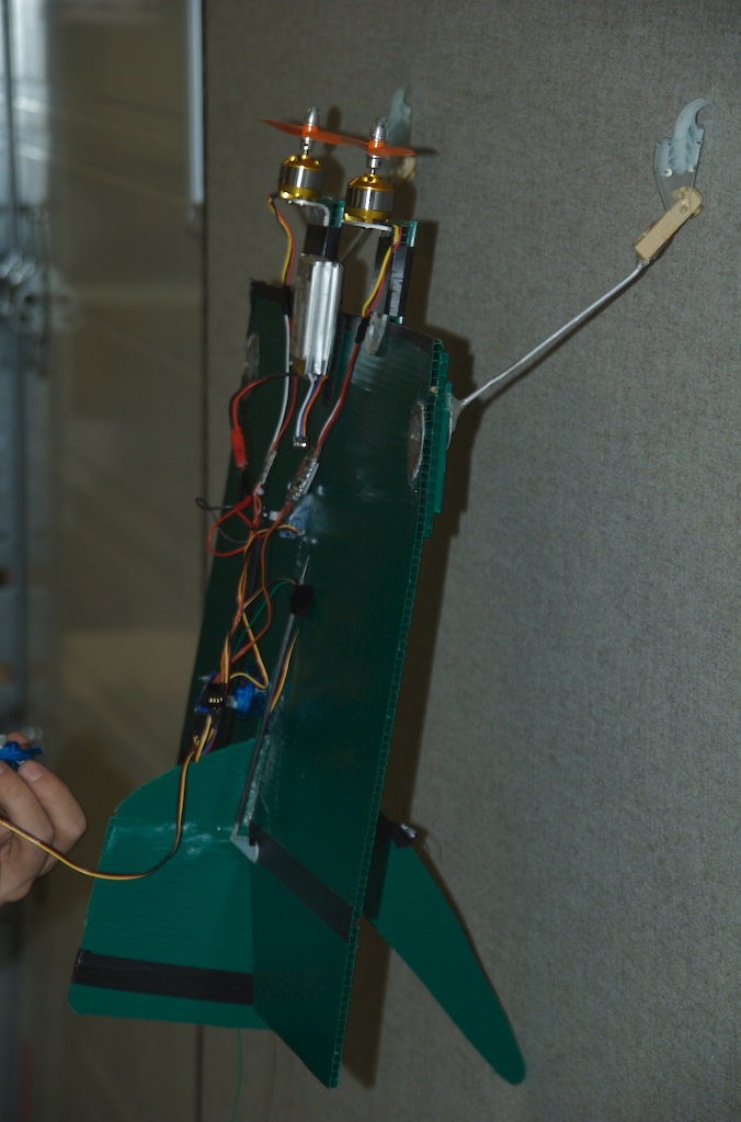
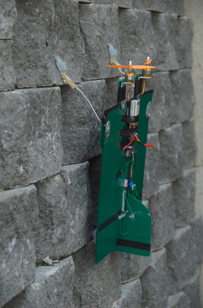
- The wall is a "carpet wall" use for cubicle
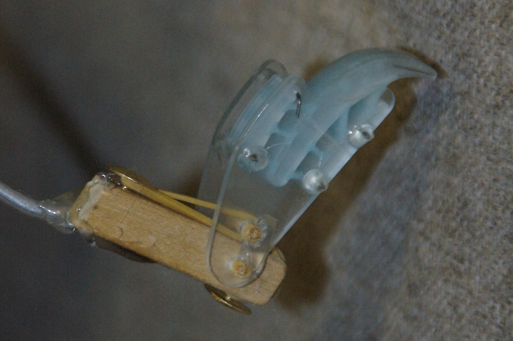
- Each foot has 8 spines.
- Compliant ankle design:
- The aircraft has two propeller, but they are not spinning in opposing direction yet... that feature would ease the control.
- We can "climb" the wall by doing small "jump"...
- The main problem is doing the maneuver that transition from horizontal flight to vertical and then dropping on the wall to attach the spine. This required a lot of timing and you lost most of the use of your control surface (in vertical flight, without propeller running, there is no flow on the control surface). We should either change the approach strategies (ie: hit the wall directly from vertical flight) or plan the dynamic maneuver (ie: like an acrobatic jumper that get all the required momentum on the ground, prior to take off, for the maneuver he intents to do).
- We crashed the aircraft (bad maneuver while close to the ground!) during outside testing and didn't had any other spare propellers! Outside testing are still a to do thing...
- 2006/10/01 - Initial experiments without spiny feet: http://www.stanford.edu/~alexisld/VamUdeS/DavidRancourt/UdeS_Flying_Machine_hq.wmv
Ideas, requests, problems regarding TWiki? Send feedback