new web: http://bdml.stanford.edu/pmwiki
TWiki > RisePrivate Web>PrivateRiSE > NewProposals>HierarchicalFabrication (10 Aug 2007, MattSpenko? )
-- MattSpenko? - 17 Jul 2007
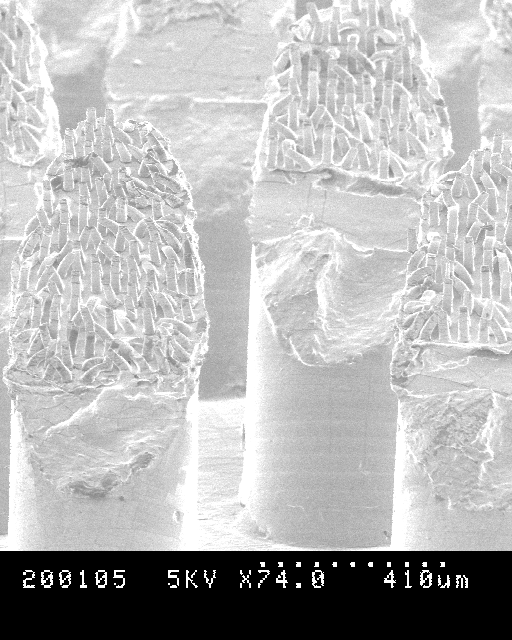
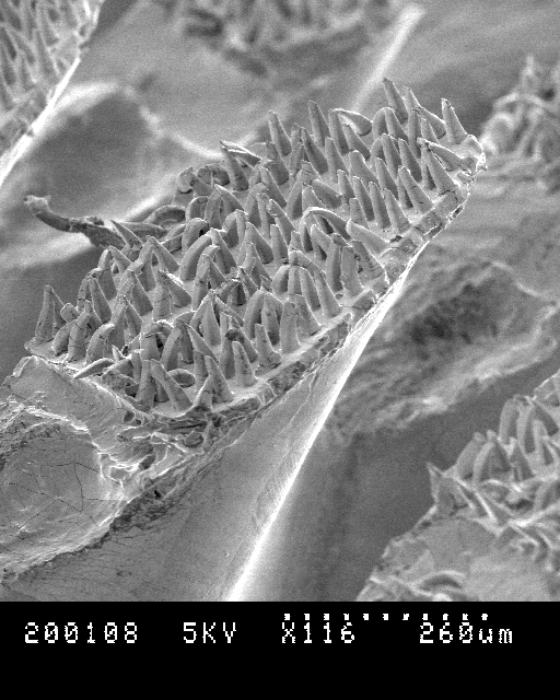
This page describes how to fabricate hierarchical structures and the results of testing these HDPS. The goal is to create small angled stalks on top of the larger angled DPS. Below is an SEM of HDPS-20. Note that there is a good deal of clumping in the right picture. This is most likely due to the shore 25A hardness of the tap blue silicone.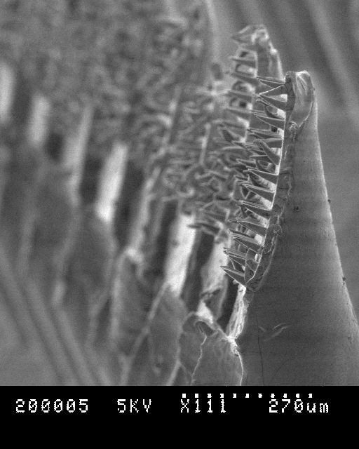
 You can download the solidworks files for the jigs here: jigsolidworksfiles.zip:
The jigs are made with varying depths ranging from 0.6 to 0.9 mm at the moment. The 0.7 mm jigs seem to be great for the standard DPS patches that we have. For some of the DPS patches with thicker backing deeper jogs will need to be made. In fact, I destroyed the two 0.7 mm jigs in some of my testing this week, so they will have to be made again. At this point you will want to do one of two things. Either you can wrap the jigs with scotch tape, which helps in the removal process, or you can coat the jigs with mold release. The mold release might have a negative impact on the molding process though - I haven't successfully tried it, but it should be at least experimented with.
You can download the solidworks files for the jigs here: jigsolidworksfiles.zip:
The jigs are made with varying depths ranging from 0.6 to 0.9 mm at the moment. The 0.7 mm jigs seem to be great for the standard DPS patches that we have. For some of the DPS patches with thicker backing deeper jogs will need to be made. In fact, I destroyed the two 0.7 mm jigs in some of my testing this week, so they will have to be made again. At this point you will want to do one of two things. Either you can wrap the jigs with scotch tape, which helps in the removal process, or you can coat the jigs with mold release. The mold release might have a negative impact on the molding process though - I haven't successfully tried it, but it should be at least experimented with.
 These are the plots for 50um stalks on DPS and for 20um stalks on DPS.
 A few things to note. First, the hierarchical stalks are yield the same force profile for each of the preload depths. This would indicate that the suspension is working, and that with even small amount of preload, we can get full adhesion. This is further exemplified in the following plot of Pulloff Force vs Preload Force. Note how it is essentially flat for preload depths of 300 to 800 um. This is very different from the DPS.
 Second, the 20um hairs and the 50um hairs have just about the same amount of adhesion; howerver the 20um stalks have a much larger force space than the 50um stalks, which is a result of larger allowable shear loads. Last, the total amount of adhesion is about 20% of the DPS alone (assuming we get 1N of force with the DPS. I know we have gotten more, up to 2N, but I don't know how repeatable that test is - Dan, can you comment?). This is to be expected since the total real contact area is drastically reduced on flat glass. However, we still need to consider what the total amount of adhesion is for the patch size, not as a function of the contact area.
Here are the results taken on a rough glass surface made from beads that are ~0.5 mm in diameter.
Second, the 20um hairs and the 50um hairs have just about the same amount of adhesion; howerver the 20um stalks have a much larger force space than the 50um stalks, which is a result of larger allowable shear loads. Last, the total amount of adhesion is about 20% of the DPS alone (assuming we get 1N of force with the DPS. I know we have gotten more, up to 2N, but I don't know how repeatable that test is - Dan, can you comment?). This is to be expected since the total real contact area is drastically reduced on flat glass. However, we still need to consider what the total amount of adhesion is for the patch size, not as a function of the contact area.
Here are the results taken on a rough glass surface made from beads that are ~0.5 mm in diameter.
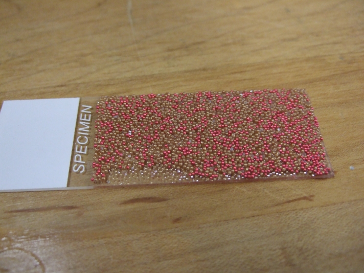 I just realized that the colored glass beads are actually coated with a paint. I thought they were just going to be colored glass. I will try to rerun the experiments with the clear glass beads that I have.
I just reran the results on the clear glass and didn't get much different. In fact the normal adhesion was a bit less. Overall I think we need to take these rough surface results with a bit of salt.
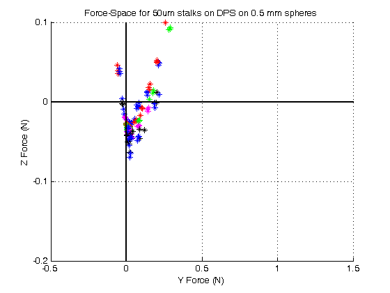
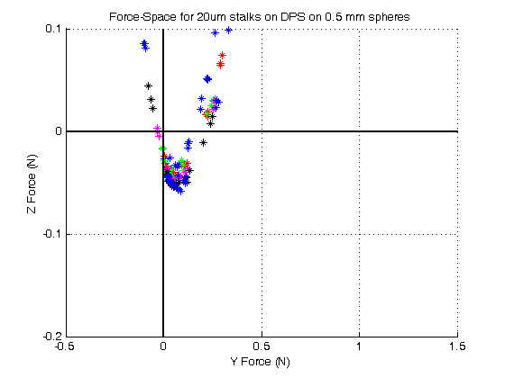
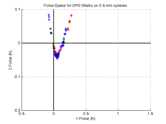
The sphericity of the beads that I got was severely lacking. I got them from blockheadstamps.com. I would recommend in the future to buy them from jaygoinc.com which is where Dan Goldman got the ones that we are used to seeing in the cockroach videos. He got some that are 0.7 mm in diameter, but I think we should experiment with smaller sizes. The sphericity is carefully controlled with the Jaygo ones. Note that the force profiles are pretty bad compared to the flat glass; however, the hierarchical stalks have ~25% more normal adhesion that the DPS alone! I think this is very promising, and if we can find some smaller glass beads, we may be able to get some higher levels of adhesion so we're not in the 0.05N range. Also note the drop off from flat to smooth, with DPS there is approximately a 95% decrease in adhesion levels. With the hierarchical stalks there is only a 70% decrease in adhesion. Again, not great, but promising. The axes are the same as above to give you an idea of just how little adhesion we are getting on the glass beads. The last picture is the DPS alone on the glass beads.
I just realized that the colored glass beads are actually coated with a paint. I thought they were just going to be colored glass. I will try to rerun the experiments with the clear glass beads that I have.
I just reran the results on the clear glass and didn't get much different. In fact the normal adhesion was a bit less. Overall I think we need to take these rough surface results with a bit of salt.
The sphericity of the beads that I got was severely lacking. I got them from blockheadstamps.com. I would recommend in the future to buy them from jaygoinc.com which is where Dan Goldman got the ones that we are used to seeing in the cockroach videos. He got some that are 0.7 mm in diameter, but I think we should experiment with smaller sizes. The sphericity is carefully controlled with the Jaygo ones. Note that the force profiles are pretty bad compared to the flat glass; however, the hierarchical stalks have ~25% more normal adhesion that the DPS alone! I think this is very promising, and if we can find some smaller glass beads, we may be able to get some higher levels of adhesion so we're not in the 0.05N range. Also note the drop off from flat to smooth, with DPS there is approximately a 95% decrease in adhesion levels. With the hierarchical stalks there is only a 70% decrease in adhesion. Again, not great, but promising. The axes are the same as above to give you an idea of just how little adhesion we are getting on the glass beads. The last picture is the DPS alone on the glass beads.
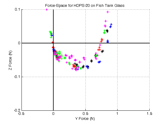
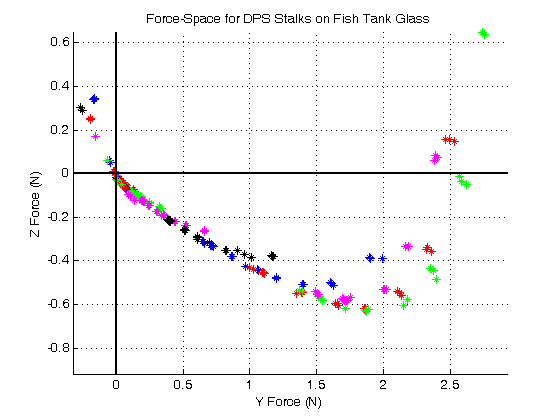
 Here are the results for HDPS-20 and DPS on fish Tank glass
Hierarchical Structures (HDPS)
-
 For 10 August 2007: RiSE_Telecon_August10_2007_v3.ppt: Slides from Noe regarding the HDPS. Also may want to download at least the first of these videos from Kellar's lab:
 - Video from N. Gravish in Kellar's lab for hiearchical structures (50um wedges on stalks) at 400um preload (AVI video - works with Divx encoder on Quicktime).
- HDPS50um500microndepth500micronpers.avi
- HDPS50umLDP250um.avi
This page describes how to fabricate hierarchical structures and the results of testing these HDPS. The goal is to create small angled stalks on top of the larger angled DPS. Below is an SEM of HDPS-20. Note that there is a good deal of clumping in the right picture. This is most likely due to the shore 25A hardness of the tap blue silicone.
How to Make HDPSs
The general idea is very simple. You can fill either the SU-8 mold with a thin layer of silicone and then placing the DPS on top of them in a loaded state. After the silicone cures unload the DPS and voila, you have a hierarchical compliance. However, the yield using this procedure is quite low and a number of problems can come up. They are as follows:- The silicone layer is too thick. Instead of a patch of hairs on a single DPS stalk, the DPS stalks are connected together. See Figure XX.
- The silicone layer is really thick, resulting in DPS stalks that are mashed together in a loaded state.
- Only the tips or the "heel" of the stalks is exposed to the SU-8 wafer resulting in a DPS stalk that does not have the entire face covered.
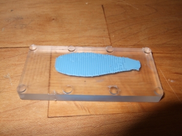
Step 1
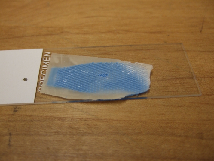
Place the DPS on the one of the jigs.
You can download the solidworks files for the jigs here: jigsolidworksfiles.zip:
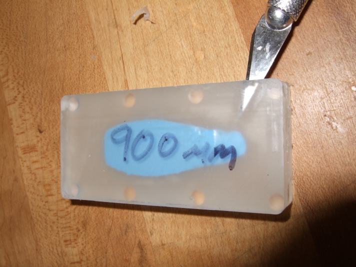
The jigs are made with varying depths ranging from 0.6 to 0.9 mm at the moment. The 0.7 mm jigs seem to be great for the standard DPS patches that we have. For some of the DPS patches with thicker backing deeper jogs will need to be made. In fact, I destroyed the two 0.7 mm jigs in some of my testing this week, so they will have to be made again. At this point you will want to do one of two things. Either you can wrap the jigs with scotch tape, which helps in the removal process, or you can coat the jigs with mold release. The mold release might have a negative impact on the molding process though - I haven't successfully tried it, but it should be at least experimented with.
Step 2
Place the other side of the jig on the stalks and load the stalks. Check under a microscope to see if they are loaded properly. I once tried a piece of double sided tape on the top of the jig and that seemed to work well to keep the hairs loaded properly, but it may not be necessary.Step 3
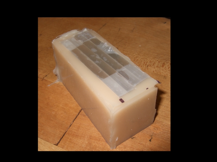
Tape the two sides of the jig together.Step 4
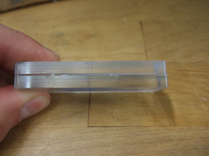
Place the piece into a deep container and fill with whatever filler mold material you like. The material must have a low enough viscosity to flow between the stalks and fill them completely.Step 5
Remove the jig from the container and take the DPS out of the jig while keeping the filler mold in place.
Step 6
Visually inspect the hairs under a microscope. Take the tip of an exacto knife and careully pull out any DPS tips that are stuck in the mold. It is perfectly OK if the tips are sticking out past the filler mold. They will get pushed back down in the next step. It is better to have the tips sticking out than to have them embedded in the filler mold.Step 7
Prepare your 20um/50um mold. You can either use the wafer directly or make a separate mold by pouring the black silicone in the wafer and then using that to make another mold. Eventually I suspect we will have to mold directly onto the wafer to ensure a good flat surface, but for now the secondary mold works fine. The mold/wafer is prepared by putting silicone on it and then spreading it out until an extremely thin layer is on the mold. You will not even really be able to see it. If you can see it then its too thick. I usually degas the silicone first and then put it on the mold, but I have also put it on the mold and then degased. Either one seems to work fine.Step 8
Clamp the mold together with the DPS/filler mold and let it sit.Step 9
Remove the DPS/filler mold and then carefully peel out the filler mold. You then may need to go in and clean up anything that did not tear properly. As I get better with the process, the less manual inspection/repair I need to doResults
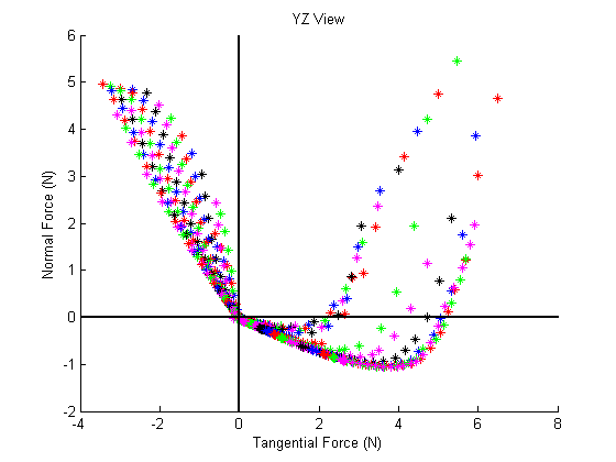
This is the typical force space plot for DPS made from the blue tap plastic silicone performed on glass.
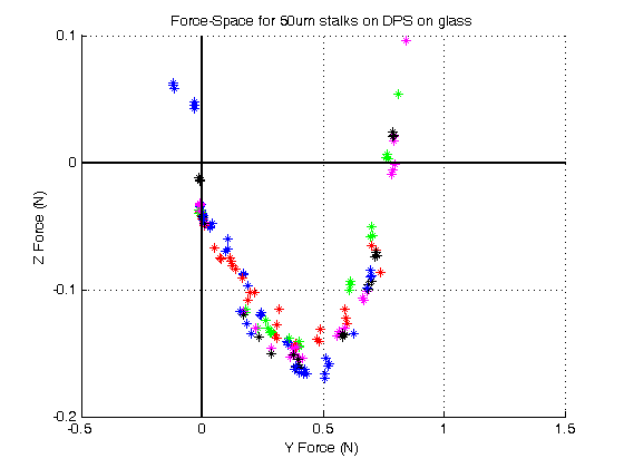
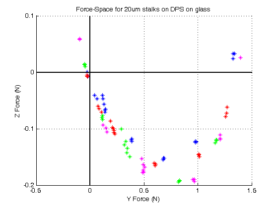
These are the plots for 50um stalks on DPS and for 20um stalks on DPS.
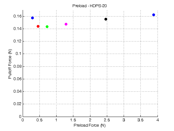
A few things to note. First, the hierarchical stalks are yield the same force profile for each of the preload depths. This would indicate that the suspension is working, and that with even small amount of preload, we can get full adhesion. This is further exemplified in the following plot of Pulloff Force vs Preload Force. Note how it is essentially flat for preload depths of 300 to 800 um. This is very different from the DPS.
Second, the 20um hairs and the 50um hairs have just about the same amount of adhesion; howerver the 20um stalks have a much larger force space than the 50um stalks, which is a result of larger allowable shear loads. Last, the total amount of adhesion is about 20% of the DPS alone (assuming we get 1N of force with the DPS. I know we have gotten more, up to 2N, but I don't know how repeatable that test is - Dan, can you comment?). This is to be expected since the total real contact area is drastically reduced on flat glass. However, we still need to consider what the total amount of adhesion is for the patch size, not as a function of the contact area.
Here are the results taken on a rough glass surface made from beads that are ~0.5 mm in diameter.
I just realized that the colored glass beads are actually coated with a paint. I thought they were just going to be colored glass. I will try to rerun the experiments with the clear glass beads that I have.
I just reran the results on the clear glass and didn't get much different. In fact the normal adhesion was a bit less. Overall I think we need to take these rough surface results with a bit of salt.
The sphericity of the beads that I got was severely lacking. I got them from blockheadstamps.com. I would recommend in the future to buy them from jaygoinc.com which is where Dan Goldman got the ones that we are used to seeing in the cockroach videos. He got some that are 0.7 mm in diameter, but I think we should experiment with smaller sizes. The sphericity is carefully controlled with the Jaygo ones. Note that the force profiles are pretty bad compared to the flat glass; however, the hierarchical stalks have ~25% more normal adhesion that the DPS alone! I think this is very promising, and if we can find some smaller glass beads, we may be able to get some higher levels of adhesion so we're not in the 0.05N range. Also note the drop off from flat to smooth, with DPS there is approximately a 95% decrease in adhesion levels. With the hierarchical stalks there is only a 70% decrease in adhesion. Again, not great, but promising. The axes are the same as above to give you an idea of just how little adhesion we are getting on the glass beads. The last picture is the DPS alone on the glass beads.
Here are the results for HDPS-20 and DPS on fish Tank glass
Discussion and Future Work
- The only thing that I think is really disappointing is the levels of adhesion that we are getting. We don't want to be quoting adhesion levels that are near the noise limit of the force sensor.
- The DPS can be made get more hairs in contact with the surface. I would recommend that 2 to 3 DPS stalks be "combined" in rows and then stalked as close as possible (in the rows, the columns are pretty much at their limit now). This should give us good compromise between independent compliance and more contact area.
- The DPS should be made out of a stiffer material or combinations of materials should be made. I think the blue silicone is too soft and a lot of hairs are clumping together, especially at the 20um scale. You can see that in the above SEM photograph. We should be able to make these out of the silgard 170 (black) or P-70 (green). I think we would then get similar adhesion with improved self-cleaning properties.
- A better rough surface needs to be found and tested on. The fish tank lid looks promising, but it is covered in grime. We need a clean surface to test.
- The 20um stalks need to be optimized. I think they should be round and placed in a hexagonal pattern to increase contact area.
- A third layer may be possible. This procedure could be repeated. However, I think we need to fabricate hairs with no clumping to do this. The sylgard-170 may be able to achieve this. For the third layer I would suggest using Draper's mold. We have one of their wafers in the lab.
- We have sent samples to Kellar. As we get more samples and higher yields we should not forget to send him samples to get videos of the hairs in action and another set of experimental data to confirm with ours.
- RiSE_Telecon_August3_2007_v2.ppt: RiSE_TeleconPresentation
- RiSE_Telecon_August3_2007_v2.ppt: RiSE_TeleconPresentation
- RiSE_Telecon_August3_2007_v2.ppt: RiSE_TeleconPresentation
- RiSE_Telecon_August3_2007_v2.ppt: RiSE_TeleconPresentation
- RiSE_Telecon_August3_2007_v2.ppt: RiSE_TeleconPresentation
- RiSE_Telecon_August3_2007_v2.ppt: RiSE_TeleconPresentation
- RiSE_Telecon_August3_2007_v2.ppt: RiSE_TeleconPresentation
- RiSE_Telecon_August10_2007_v3.ppt: RiSE_TeleconPresentation
Ideas, requests, problems regarding TWiki? Send feedback